Accuair height sensors on a 95-00 LS400! Done!
 05-04-14, 11:09 PM
#1
So PD and others asked me to post how I sorted out my accuair height sensors since nobody has really done so.
Let me say first, that this was somewhat difficult to figure out at first, but that was partially because I was 5days into a massive build and not thinking/seeing straight. Took a second set of eyes and the clear head of my buddy to figure out what was staring me right in the face.
What you need:
2 pieces of 2x3x1/16" mild steal
MIG or TIG welder, mig is faster/easier.
Assorted small high speed ferrous drill bits
Compact drill
Self-etching primer
Black spray paint.
Rotors cutoff tool/dremel/grinder w zipdiscs
Nutsert/rivnut tool ($17 @ harbour freight) with 10-24 nutserts:

Fronts are super simple. In the channel behind the shock locate the sensor against the forward edge. Mark one side and pilot drill. Fresh sharp drill bits are a must, you are going through a frame rail and it's not easy work on a drill. Step the bit size up to the OD of the nutsert. Drill and install the nutsert. Mount sensor with the backing/spacer plate, pilot drill the other hole, remove and step up bit size to install the other nutsert. Mount sensor with spacer plate, connect link to arm and other end to the small tab off the lower shock mount.

Ls400 height sensor locations by ZX3Tuning, on Flickr
Passenger side froth sensor
I positioned my sensor higher then needed, and only go through about 2/3s the stroke of the sensor, I'll probably lower the sensor by 1-2" and move the link to the 2nd outer point on the arm.
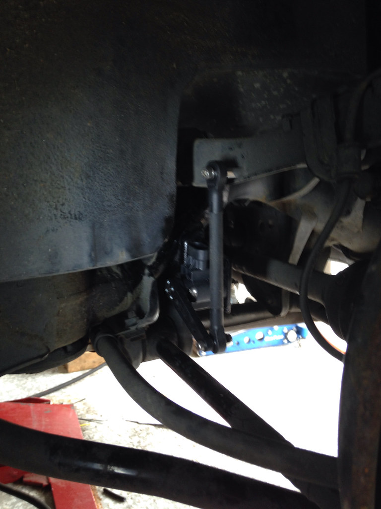
For the rear, it helps to pre-drill the plates to mount the sensors before tacking and welding in place. We did 2x2 plates but 2x3 plates with the 3" dimension extending laterally would give you more mounting flexibility and ease of install. With the plate tacked to the sub frame, check the sensor position to the upper control arm before finish welding it in.
Once welded in and cool to the touch, shoot it with a couple light coats of the etching primer and let dry followed by a couple light coats of black and let dry.
Once dry, mount the sensors with the backing plates. Use the supplied hardware from accuair to space the link away from the upper control arm, set sensor arm to lowest point in its suggested travel and measure up to the control arm to mark a point to connect the upper link. Should be about 2.3-3" out from the OD of the UCA bushing cup. Drill from between the axel and UCA, being careful not to drill to low and close the the lip of the UCA. Bolt the hex-spacer to the arm and the link to the other side of the hex spacer. Let dangle and measure to the sensor arm at its lowest point, it's easiest to remove one of the links to figure out where the arm will sit and approximate the integral stopping point of the threaded link.
Cut the threaded section, clean up the threads on the face of your cutoff tool/grinder/etc, cut the rubber guide, assemble and install!
DONE!
Ls400 height sensor locations by ZX3Tuning, on Flickr *
Driver side sensor
Ls400 height sensor locations by ZX3Tuning, on Flickr *
Passenger side sensor from rear
Ls400 height sensor locations by ZX3Tuning, on Flickr
Passenger side sensor from wheel hub
If you do not have a welder but have access to a brake, or are just a crafty individual, you can make a bolt-in version using existing factory bolt points for the factory air cars.
BETTER pics to follow later...
Let me say first, that this was somewhat difficult to figure out at first, but that was partially because I was 5days into a massive build and not thinking/seeing straight. Took a second set of eyes and the clear head of my buddy to figure out what was staring me right in the face.
What you need:
2 pieces of 2x3x1/16" mild steal
MIG or TIG welder, mig is faster/easier.
Assorted small high speed ferrous drill bits
Compact drill
Self-etching primer
Black spray paint.
Rotors cutoff tool/dremel/grinder w zipdiscs
Nutsert/rivnut tool ($17 @ harbour freight) with 10-24 nutserts:
Fronts are super simple. In the channel behind the shock locate the sensor against the forward edge. Mark one side and pilot drill. Fresh sharp drill bits are a must, you are going through a frame rail and it's not easy work on a drill. Step the bit size up to the OD of the nutsert. Drill and install the nutsert. Mount sensor with the backing/spacer plate, pilot drill the other hole, remove and step up bit size to install the other nutsert. Mount sensor with spacer plate, connect link to arm and other end to the small tab off the lower shock mount.
Ls400 height sensor locations by ZX3Tuning, on Flickr
Passenger side froth sensor
I positioned my sensor higher then needed, and only go through about 2/3s the stroke of the sensor, I'll probably lower the sensor by 1-2" and move the link to the 2nd outer point on the arm.
For the rear, it helps to pre-drill the plates to mount the sensors before tacking and welding in place. We did 2x2 plates but 2x3 plates with the 3" dimension extending laterally would give you more mounting flexibility and ease of install. With the plate tacked to the sub frame, check the sensor position to the upper control arm before finish welding it in.
Once welded in and cool to the touch, shoot it with a couple light coats of the etching primer and let dry followed by a couple light coats of black and let dry.
Once dry, mount the sensors with the backing plates. Use the supplied hardware from accuair to space the link away from the upper control arm, set sensor arm to lowest point in its suggested travel and measure up to the control arm to mark a point to connect the upper link. Should be about 2.3-3" out from the OD of the UCA bushing cup. Drill from between the axel and UCA, being careful not to drill to low and close the the lip of the UCA. Bolt the hex-spacer to the arm and the link to the other side of the hex spacer. Let dangle and measure to the sensor arm at its lowest point, it's easiest to remove one of the links to figure out where the arm will sit and approximate the integral stopping point of the threaded link.
Cut the threaded section, clean up the threads on the face of your cutoff tool/grinder/etc, cut the rubber guide, assemble and install!
DONE!
Ls400 height sensor locations by ZX3Tuning, on Flickr *
Driver side sensor
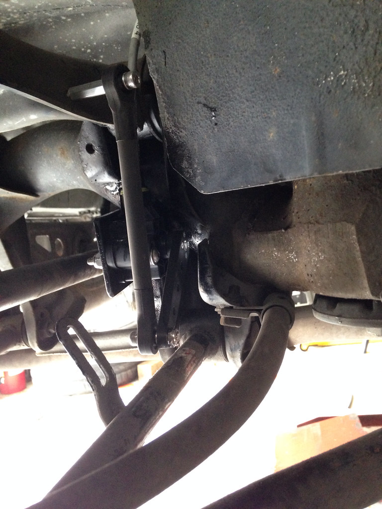
Ls400 height sensor locations by ZX3Tuning, on Flickr *
Passenger side sensor from rear
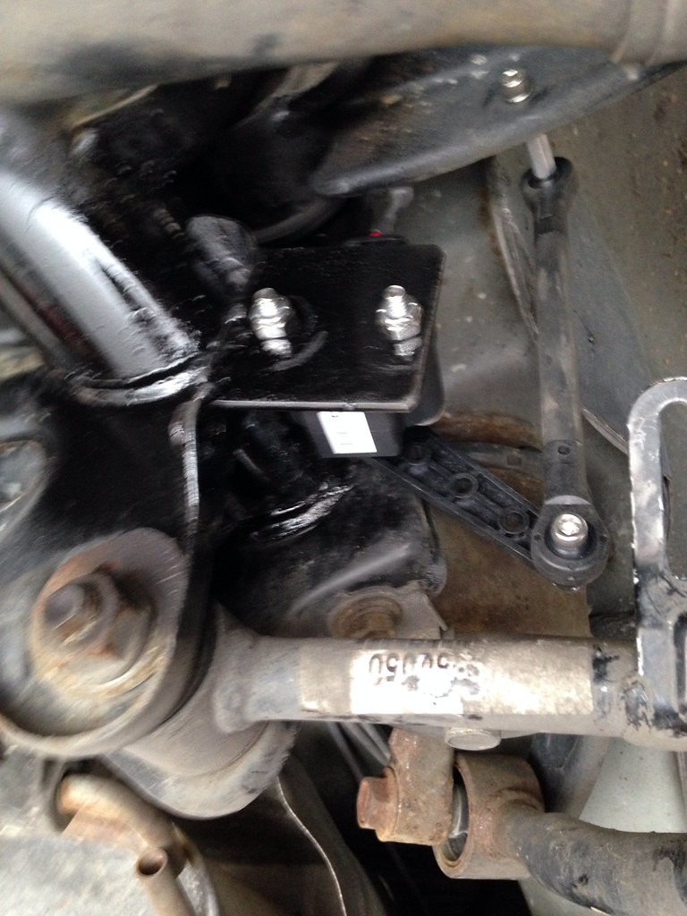
Ls400 height sensor locations by ZX3Tuning, on Flickr
Passenger side sensor from wheel hub
If you do not have a welder but have access to a brake, or are just a crafty individual, you can make a bolt-in version using existing factory bolt points for the factory air cars.
BETTER pics to follow later...
Last edited by Shmee; 05-05-14 at 12:16 AM.


 05-05-14, 04:51 PM
#4
I was going to use the toe arm, as the passenger side comes with that bracket already on the arm, but then my test stroke of the suspension was putting the arc of the sensor arm and the arc of the toe arm into a binding scenario at about � travel. You also have to cut about 1/4" off each of the links so they are only about 1.75" from bolt center to bolt center. Which was why it was binding. I'm guessing the height sensor arms on the OEM air cars are probably pretty long and travel with a fairly similar arc.
With how I have it now, I can sit the rear tire well right on top of the tire without binding.... That's not where I'm got to set it, just saying.
With how I have it now, I can sit the rear tire well right on top of the tire without binding.... That's not where I'm got to set it, just saying.
05-05-14, 06:43 PM
#7
maybe it's just my interpretation of your pictures but it seems as if the rear sensors will only get roughly a 1" swing from up to down, due to your endlink placement. i don't know how sensitive the sensors are to small increments so we'll see when it's all wired together and programmed! can't wait!!!
Trending Topics

Thread
Thread Starter
Forum
Replies
Last Post
akswagga
LS - 1st and 2nd Gen (1990-2000)
11
06-06-15 08:47 PM