How to: Add "Smart" IPOD/AUX input to Factory Lexus System in 10 Steps
 04-18-07, 12:31 AM
#1
Pole Position
Thread Starter
Join Date: Jan 2005
Location: Nightmare on Elm St.
Posts: 291
Likes: 0
Received 0 Likes
on
0 Posts
Ok guys,
Saw a few threads and decided to give something back to the community that gave me so much
A few people here have been fairly successful at adding an IPOD to their system by hacking into the changer and Pioneer system.
Unfortunately, I have the Nakamichi and isn't as forgiving to manipulate at the headunit level, so I was forced to use the low road and intercept at the CD Changer.
What makes this process so "Smart" and different, than this thread?
https://www.clublexus.com/forums/sho...d.php?t=269156
Pros:
Basic Level----------
*Relay circuit senses low audio current on input (IPOD) and automatically switches to the IPOD, etc.
*The AUX source will stay on once switched for 10 seconds after it goes silent. This buys you time to change the track, folder, etc.
* After ten seconds, it assumes that you are either done or the IPOD has been removed, and it switches back to the CD changer by itself.
*Easier to wire - Novice level, less than 10 steps explained in here.
Advanced----------
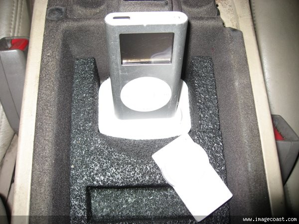
* Added a dock in the armrest for the IPOD to charge and preamp output (cleaner sound).
*IPOD completely hidden when armrest is closed, which minimizes car break-in risk.
*Added RF remote from iJet to control the IPOD with the armrest closed via wireless remote. Works from outside the car if desired.
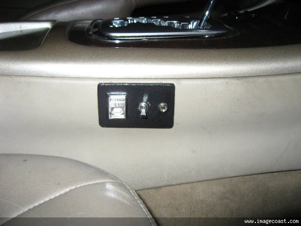
* 2 AUX Inputs- Added 3.5mm AUX input for laptop,PSP, etc.
Cons:
*Still have to have a working CD changer
*Not cheap, Expect approx. $100 in costs- If you would for it to cost less than half this and don't mind adding a switch for the AUX, the tutorial above is a better option.
Interested, then read on.......
Basically, there is already a product on the market that will do 98% of the work with hooking up only 2 extra wires- 12+ and ground.
It is the PIE SON-AUX unit- Retail $95 shipped [ Have 1 extra ]
]
http://www.pie.net/store/index.cfm?a...ils&ItemID=127
It was made to switch between 2 CD changers, but will work to switch from your stock CD changer and IPOD on a stock system.
-------------------------------------------------------------
Basic Products Needed:
(1) PIE SON-AUX relay box
(2) RCA female sets (2 per set)
(2) RCA male connectors
(2) RCA female-to-female coupler/connector
(1) 3.5mm stereo plug to RCA male.
(1) 12 ft/ 16 ft RCA male twisted-pair patch cable
Tools:
solder skills
solder
electrical tape
wiring diagram for specific Lexus model audio system (so we know which wires to hack)
soldering iron
IPOD or similar device
--------------------------------------------------------
Basic setup: [***Solder all wires***]
1) Tap into the CD Changer 12+ ACC wire for the SON-AUX power lead.
2) Tap into the CD Changer or AMP ground wire for the SON-AUX ground lead.
3) Cut the 4 wires from your CD Changer to your AMP that carries the (L+, L-, R+, R-) leads. Leave atleast 4 inches of wires from any connector.
4) Wire 1 set (that means 2 total) of RCA female plugs onto the wires that you just cut that lead to the amp. Make sure you label the wires careful and remember which female RCA is left and right. I used white and red electrical tape to mark the connectors.
5) Wire 1 set of RCA male plugs onto the wires that you just cut that lead to the stock CD Changer. Mark carefully again.
6) Almost done!!
7) Get a 3.5mm to RCA male stereo Y- connector and your IPOD. time to test before bringing into the cabin for you SC guys. Hook the IPOD into the 2 female leads built into the son-aux unit.
Once you hit play, then CD changer should stop playing and play your IPOD.
If you do not hear anything, check your wiring and turn IPOD to maximum volume.
Great. We have sound!!
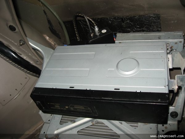
8) From here, get a set of 12 or 16 ft "twisted pair"-ONLY RCA male patch cables and plug into the SON-AUX unit, where you had the IPOD plugged in.
Run cables into the cabin.
9) Once in the cabin, get 2 RCA female-to-female couplers and connect one end to the patch cables you just pulled in and the other side of the couplers should be connect to your IPOD Y-cable that we used to test the system.
10) Viola- Mount in a suitable location and you are done!!
Advanced*********
1) If 2 AUX inputs are desired- A SPDT switch should be used to have an IPOD and a AUX input jack. The switch will select either the jack or your IPOD. The output from the switch should been sent to the patch cables.
A few final pics to help you out
Saw a few threads and decided to give something back to the community that gave me so much
A few people here have been fairly successful at adding an IPOD to their system by hacking into the changer and Pioneer system.
Unfortunately, I have the Nakamichi and isn't as forgiving to manipulate at the headunit level, so I was forced to use the low road and intercept at the CD Changer.
What makes this process so "Smart" and different, than this thread?
https://www.clublexus.com/forums/sho...d.php?t=269156
Pros:
Basic Level----------
*Relay circuit senses low audio current on input (IPOD) and automatically switches to the IPOD, etc.
*The AUX source will stay on once switched for 10 seconds after it goes silent. This buys you time to change the track, folder, etc.
* After ten seconds, it assumes that you are either done or the IPOD has been removed, and it switches back to the CD changer by itself.
*Easier to wire - Novice level, less than 10 steps explained in here.
Advanced----------
* Added a dock in the armrest for the IPOD to charge and preamp output (cleaner sound).
*IPOD completely hidden when armrest is closed, which minimizes car break-in risk.
*Added RF remote from iJet to control the IPOD with the armrest closed via wireless remote. Works from outside the car if desired.
* 2 AUX Inputs- Added 3.5mm AUX input for laptop,PSP, etc.
Cons:
*Still have to have a working CD changer
*Not cheap, Expect approx. $100 in costs- If you would for it to cost less than half this and don't mind adding a switch for the AUX, the tutorial above is a better option.
Interested, then read on.......
Basically, there is already a product on the market that will do 98% of the work with hooking up only 2 extra wires- 12+ and ground.
It is the PIE SON-AUX unit- Retail $95 shipped [ Have 1 extra
]http://www.pie.net/store/index.cfm?a...ils&ItemID=127
It was made to switch between 2 CD changers, but will work to switch from your stock CD changer and IPOD on a stock system.
-------------------------------------------------------------
Basic Products Needed:
(1) PIE SON-AUX relay box
(2) RCA female sets (2 per set)
(2) RCA male connectors
(2) RCA female-to-female coupler/connector
(1) 3.5mm stereo plug to RCA male.
(1) 12 ft/ 16 ft RCA male twisted-pair patch cable
Tools:
solder skills
solder
electrical tape
wiring diagram for specific Lexus model audio system (so we know which wires to hack)
soldering iron
IPOD or similar device
--------------------------------------------------------
Basic setup: [***Solder all wires***]
1) Tap into the CD Changer 12+ ACC wire for the SON-AUX power lead.
2) Tap into the CD Changer or AMP ground wire for the SON-AUX ground lead.
3) Cut the 4 wires from your CD Changer to your AMP that carries the (L+, L-, R+, R-) leads. Leave atleast 4 inches of wires from any connector.
4) Wire 1 set (that means 2 total) of RCA female plugs onto the wires that you just cut that lead to the amp. Make sure you label the wires careful and remember which female RCA is left and right. I used white and red electrical tape to mark the connectors.
5) Wire 1 set of RCA male plugs onto the wires that you just cut that lead to the stock CD Changer. Mark carefully again.
6) Almost done!!
7) Get a 3.5mm to RCA male stereo Y- connector and your IPOD. time to test before bringing into the cabin for you SC guys. Hook the IPOD into the 2 female leads built into the son-aux unit.
Once you hit play, then CD changer should stop playing and play your IPOD.
If you do not hear anything, check your wiring and turn IPOD to maximum volume.
Great. We have sound!!
8) From here, get a set of 12 or 16 ft "twisted pair"-ONLY RCA male patch cables and plug into the SON-AUX unit, where you had the IPOD plugged in.
Run cables into the cabin.
9) Once in the cabin, get 2 RCA female-to-female couplers and connect one end to the patch cables you just pulled in and the other side of the couplers should be connect to your IPOD Y-cable that we used to test the system.
10) Viola- Mount in a suitable location and you are done!!
Advanced*********
1) If 2 AUX inputs are desired- A SPDT switch should be used to have an IPOD and a AUX input jack. The switch will select either the jack or your IPOD. The output from the switch should been sent to the patch cables.
A few final pics to help you out
Last edited by Lex*Toy; 04-18-07 at 02:58 AM.
 04-18-07, 02:04 AM
#2

great tut on using a ready-made device in contrast to building one (which i understand is putting many people off on my tutorial). i prefer total control over my audio since pie's been having some quality issues as of late.
there is a couple points i think u may want to address:
1-no idea what you meant by "thump". if properly installed there should be no noticeable thump/bump/grind/ or doom when switching between sources.
2-could you clarify the way the SPDT switch is wired. unless im not reading something correctly u should be needing to switch 4 wires back and forth mind you im not overly familiar with the way the SON-AUX works so the spdt swich may be used as a trigger, at which point i kinda need to ask why its a spdt switch
also, just to confirm, the nak. system on later model SC3/400's uses the same type of modification as the pioneer since the changer is STILL pushed through what is called a "D/A converter". the only difference is that you are limited to tapping the signal at one of these 2 places.
also, i dont really see the big improvement if u have to wire a switch to go between sources? it just seems like its $95 for the ability to not having to flip a switch.
dont get me wrong, im not tryin to discourage you or even downplay your method, i just don't see what makes it so "smart". i think this is a great solution for people who dont feel up to the task of making their own relay setup
there is a couple points i think u may want to address:
1-no idea what you meant by "thump". if properly installed there should be no noticeable thump/bump/grind/ or doom when switching between sources.
2-could you clarify the way the SPDT switch is wired. unless im not reading something correctly u should be needing to switch 4 wires back and forth
mind you im not overly familiar with the way the SON-AUX works so the spdt swich may be used as a trigger, at which point i kinda need to ask why its a spdt switchalso, just to confirm, the nak. system on later model SC3/400's uses the same type of modification as the pioneer since the changer is STILL pushed through what is called a "D/A converter". the only difference is that you are limited to tapping the signal at one of these 2 places.
also, i dont really see the big improvement if u have to wire a switch to go between sources?
it just seems like its $95 for the ability to not having to flip a switch.dont get me wrong, im not tryin to discourage you or even downplay your method, i just don't see what makes it so "smart". i think this is a great solution for people who dont feel up to the task of making their own relay setup
04-18-07, 02:45 AM
#3
Pole Position
Thread Starter
Join Date: Jan 2005
Location: Nightmare on Elm St.
Posts: 291
Likes: 0
Received 0 Likes
on
0 Posts
there is a couple points i think u may want to address:
1-no idea what you meant by "thump". if properly installed there should be no noticeable thump/bump/grind/ or doom when switching between sources.
2-could you clarify the way the SPDT switch is wired. unless im not reading something correctly u should be needing to switch 4 wires back and forth mind you im not overly familiar with the way the SON-AUX works so the spdt swich may be used as a trigger, at which point i kinda need to ask why its a spdt switch
1-no idea what you meant by "thump". if properly installed there should be no noticeable thump/bump/grind/ or doom when switching between sources.
2-could you clarify the way the SPDT switch is wired. unless im not reading something correctly u should be needing to switch 4 wires back and forth
mind you im not overly familiar with the way the SON-AUX works so the spdt swich may be used as a trigger, at which point i kinda need to ask why its a spdt switch It is only another option. Before this post there was only 1 way to do it publicly, now there are 2.There are two different types of people- "lowest cost" and "best". By that I mean some people don't mind spending a $100 or so if it means that they will be able to do it themselves w/ more benefits.
Your thread is great and I understand it b/c Im technically inclined, but it seems that a lot of people aren't that savvy to wire 4 relays in series without a problem.
Hence the easier method above.
Now onto your questions:.
1) There is NOT any "thump" or "turn-on pop" as it is known in the industry. This sometimes occurs when relays switch between 2 independent sources. Not the case here.
2) There doesn't need to be a SPDT switch at all for 1 AUX input. I chose it because instead of adding 1 AUX input, I chose to add 2 AUX inputs. One IPOD, One external jack (laptop, etc). In the case of my setup, I used the SPDT switch to choose between which additional source.
3) Personally, I felt it cumbersome to prey play, then flip a switch to select the IPOD. It is also more wiring, which can cause more points of failure. Again, the switch can be avoided all together.
Hopefully, I have answered your questions. And to be more fair, I am listing the more expensive price of this setup in the CONS. If they want to spend ~$30 they can choose your route, as mine will be more of an investment.
Last edited by Lex*Toy; 04-18-07 at 03:08 AM.
04-18-07, 09:45 AM
#4
Lexus Test Driver

Hey man --
Thanks for the info--
PLEASE reverse engineer the circuitry of the unit and post comments-- I guarantee they're using a darlington array(pair of transistors sort of wired in series) and a capacitor setup for the turn off delay (after power store bleeds off)--
OR -- Take a high res picture of the circuit board components and the reverse side to show the traces where I can get a good idea of what they're doing--
This is a shortcut to designing one-- but I am confident it can be done fairly easily once we know the proper values of the components they used-- (that skips the electrical engineering part-- I'm studying for mechanical ) --
Thanks for giving us this option--
I doubt there would be any problems with PIE's design at all-- as it's just a smart switch-- so it shouldn't interfere with sound quality any whatsoever..
04-23-07, 08:09 AM
#5
Pole Position
Join Date: Jun 2004
Location: VA
Posts: 254
Likes: 0
Received 0 Likes
on
0 Posts
Lex*Toy - first of all, great write-up!
I have a few questions about your procedure, so if you will please bear with me...
1. I have a 2000 SC4 w/ Nakamichi (just like you) - do you have a wiring diagram that you can send me? If not, the wire colors (+12V, ground, L+, L-, R+, R-) will do just as well I would think.
2. Looking at Steps 3-5 of your basic setup, it isn't clear to me whether you still retain full use of the factory CD changer (you mention cutting the wires leading to and from the amp and cd changer). Could you clarify/elaborate?
3. Which iJET RF remote did you use?
4. Where did you connect the +12V and ground for the docking station (BTW what kind of docking station do you have?) to charge the iPOD?
5. More and/or detailed pics please!
Thanks again for the great info!
Last edited by sc300n00b; 04-23-07 at 09:13 AM.
04-23-07, 11:53 AM
#6
Pole Position
Thread Starter
Join Date: Jan 2005
Location: Nightmare on Elm St.
Posts: 291
Likes: 0
Received 0 Likes
on
0 Posts
Lex*Toy - first of all, great write-up!
I have a few questions about your procedure, so if you will please bear with me...
1. I have a 2000 SC4 w/ Nakamichi (just like you) - do you have a wiring diagram that you can send me? If not, the wire colors (+12V, ground, L+, L-, R+, R-) will do just as well I would think.
I have a few questions about your procedure, so if you will please bear with me...
1. I have a 2000 SC4 w/ Nakamichi (just like you) - do you have a wiring diagram that you can send me? If not, the wire colors (+12V, ground, L+, L-, R+, R-) will do just as well I would think.
The wires you are cutting are responsible only for the output sound from your CD changer to your Amp. Once 1 wire is cut, you are left with 2 ends. 1 end leads to the CD changer (output) and the other to your amp (input). So we are adding 2 output for 1 input. This is why the relay is needed.
You will wire steps 4 and 5. Each RCA plug (male or female), has 2 wires inside. The bare wire that is wrapped around the protected on is the "negative". The protected wire is the "positive" lead. From here you can use the diagram to "match" (L) pos and neg & (R) pos and neg wires.
"PureDrifter" used great pictures when he was wiring his RCA female connectors in his thread. You can look there is you need them.
Once this is done, it is all plug and play.
Had an old one from last year. It is just called ABT iJet. Works great, except you just have to know what song you are listening to or press next. Will upgrade to the iJet LCD remote so that I can have a display of the current song playing.
Check www.davidnavone.com for info on power isolation products.
Sorry, I work in a blaze. Whenever I try to take pics, its slows me down so much that I lose my thought process.
Let me know what pics you need and I might be able to "Recreate" something for you.
Good luck.

Thread
Thread Starter
Forum
Replies
Last Post
Nberke
ES - 1st to 4th Gen (1990-2006)
7
01-15-11 03:52 PM
russian
Lexus Audio, Video, Security & Electronics
29
08-07-08 05:53 PM
Tymboo
Lexus Audio, Video, Security & Electronics
12
05-10-06 12:38 PM