
Need help with some wiring..


Thread Starter
Rookie
Joined: May 2011
Posts: 70
Likes: 0
From: WA
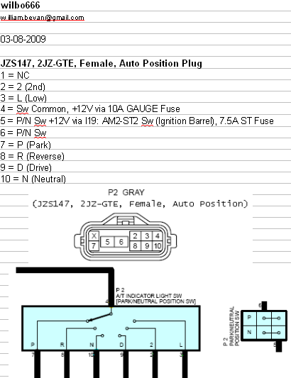
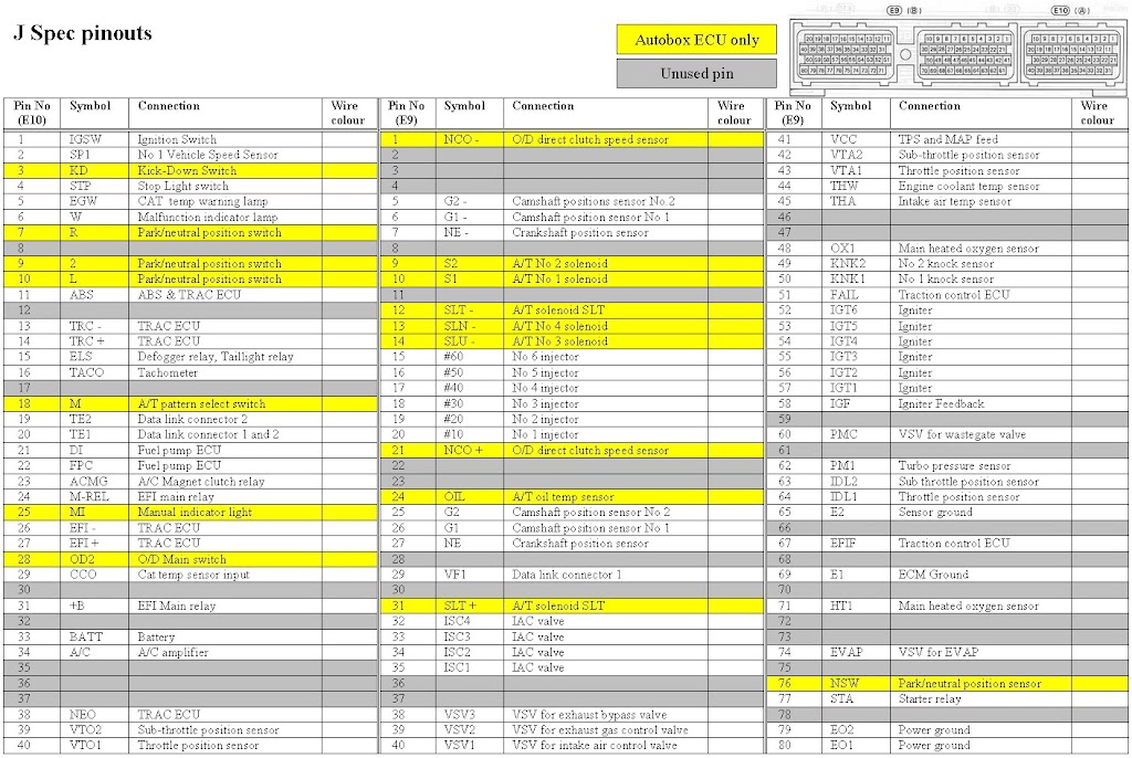
Hey guys, i've searched and searched and i'm trying to find the pinouts for the A340e (Aristo GTE) transmission and a few other things. I have managed to find this, which seems accurate. But I still need the pinouts for the VSS's and some more randoms.
This harness has been pretty much made from scratch by my brother and I. The previous owner DJ Zack sold me a POS.
(I flew all the way from Kansas to New York to drive it back, only to find out about 30 min later that it had a BHG) After pulling the motor apart, we found that there were 2 head bolts that were FINGER TIGHT! Also had 4 cracked piston ring glands... A big thanks to DJ Zack, F#@@@! But thats a story for another day.
Not only did we have to make this harness, since the previous harness was complete garbage, we also had to extend it so my AEM EMS wasn't chillin' in the engine bay. 1600 $ is too much for me to leave exposed to the elements.
I understand not all of these come from the trans lol but if anyone can give me some details on where I can locate these wires to pin INTO my ECU, I would greatly appreciate it!
The wires i need to wire to my ECU (AEM EMS V2)
On ECU ---- Description
2A----Vehicle Speed Sensor
3A ---- Kickdown Switch
4A ---- Brake Switch Input <<<Pretty sure this comes from the brake switch (12V)
7A ---- Reverse Indicator Input <<<< I beleive this is in the diagram above
18A ---- Trans Mode Selector Switch
25A ---- Trans Mode Light
28A ---- Over Drive Switch Input
34A ----- A/C Signal fro A/C Amplifier
I currently have ALL the wires pinned from the B side of the engine harness plug, the only reason i'm missing these is because the previous owner decided to cut them. The body plug harness is all hacked to hell.

Also here are some pics of the carnage we had to deal with, cause everyone just wants to see pics anyways..lol

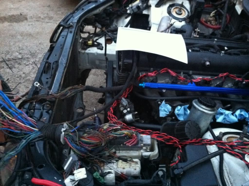

(THIS IS NOT HOW THE ENGINE BAY LOOKS CURRENTLY) Once running, everything will be cleaned up and tucked. It's just a lot easier to deal with wiring when its not in sheathing..
Here are some of the shielded cables we made with USB 2.0 cables for the Knock, Cam and Crank signals. In case you didn't know, yes, the wires running to those sensors MUST be shielded!

Here is how she sits now, 295's in the rear on 18x10 F-BBS's

She will be getting a paint job once running right Glacier Frost Mica, of course =]

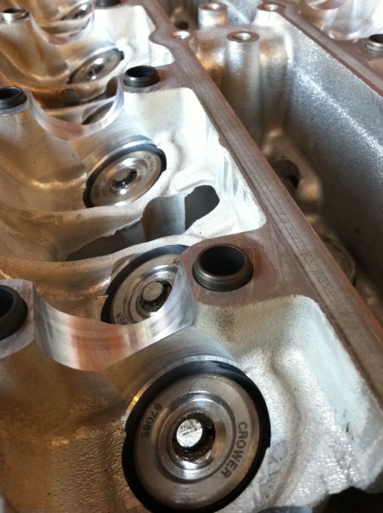
Like I said, I had to rebuild the engine so here it is right after the machine shop.

CP internals! ARP Headstuds

Crower valvesprings and retainers, going to run GSC S1's
Ross Machine Racing fuel rail and Precision 1260cc injectors

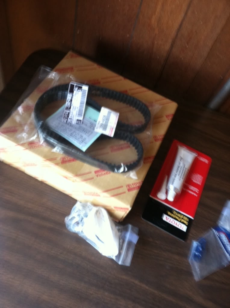
OEM parts
I wrapped my downpipe with exhaust wrap to try and keep under hood temps down!

This harness has been pretty much made from scratch by my brother and I. The previous owner DJ Zack sold me a POS.
(I flew all the way from Kansas to New York to drive it back, only to find out about 30 min later that it had a BHG) After pulling the motor apart, we found that there were 2 head bolts that were FINGER TIGHT! Also had 4 cracked piston ring glands... A big thanks to DJ Zack, F#@@@! But thats a story for another day.
Not only did we have to make this harness, since the previous harness was complete garbage, we also had to extend it so my AEM EMS wasn't chillin' in the engine bay. 1600 $ is too much for me to leave exposed to the elements.
I understand not all of these come from the trans
lol but if anyone can give me some details on where I can locate these wires to pin INTO my ECU, I would greatly appreciate it! The wires i need to wire to my ECU (AEM EMS V2)
On ECU ---- Description
2A----Vehicle Speed Sensor
3A ---- Kickdown Switch
4A ---- Brake Switch Input <<<Pretty sure this comes from the brake switch (12V)
7A ---- Reverse Indicator Input <<<< I beleive this is in the diagram above
18A ---- Trans Mode Selector Switch
25A ---- Trans Mode Light
28A ---- Over Drive Switch Input
34A ----- A/C Signal fro A/C Amplifier
I currently have ALL the wires pinned from the B side of the engine harness plug, the only reason i'm missing these is because the previous owner decided to cut them. The body plug harness is all hacked to hell.
Also here are some pics of the carnage we had to deal with, cause everyone just wants to see pics anyways..lol
(THIS IS NOT HOW THE ENGINE BAY LOOKS CURRENTLY) Once running, everything will be cleaned up and tucked. It's just a lot easier to deal with wiring when its not in sheathing..
Here are some of the shielded cables we made with USB 2.0 cables for the Knock, Cam and Crank signals. In case you didn't know, yes, the wires running to those sensors MUST be shielded!
Here is how she sits now, 295's in the rear on 18x10 F-BBS's
She will be getting a paint job once running right Glacier Frost Mica, of course =]
Like I said, I had to rebuild the engine so here it is right after the machine shop.
CP internals! ARP Headstuds
Crower valvesprings and retainers, going to run GSC S1's
Ross Machine Racing fuel rail and Precision 1260cc injectors
OEM parts
I wrapped my downpipe with exhaust wrap to try and keep under hood temps down!
Last edited by AMA0627; Mar 15, 2012 at 07:28 PM.
Yeah buying other people unfinished projects typically turns into a headache, but at least it looks like your gonna step it up quite a bit.
Here's some random diagrams you may be able to work with.
The shows which pins are used for which gears and may help: jzs147

Here is the reverse circuit: jzs161

Here is the shift lock circuit: jzs161

Here is some additional auto/ect/ecu wiring: jzs161
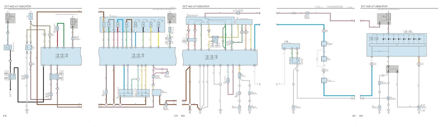
And here are some more ecu pin charts: jzs147

Hope this may help you some, let me know if you have a specific question or wire your trying to track, I do what I can for you.
Good Luck!
Here's some random diagrams you may be able to work with.
The shows which pins are used for which gears and may help: jzs147
Here is the reverse circuit: jzs161
Here is the shift lock circuit: jzs161
Here is some additional auto/ect/ecu wiring: jzs161
And here are some more ecu pin charts: jzs147
Hope this may help you some, let me know if you have a specific question or wire your trying to track, I do what I can for you.
Good Luck!
Last edited by 99 GS3; Mar 16, 2012 at 12:50 PM.
I realize this one pic is not very legible, if you think anything on this diagram may be helpful to you just send me an email address and I can send you the uncompressed fullsize image that you can zoom in on crystal clear.
Thread Starter
Rookie
Joined: May 2011
Posts: 70
Likes: 0
From: WA
Thanks, i'll let you know if I have any questions!


Thread
Thread Starter
Forum
Replies
Last Post