2ES Project Thread: Custom LED Lighting
 06-06-09, 10:08 PM
#1
Hello all, just want to do a project thread documenting my progress in making custom LED lighting for my 2ES. This will be a first time serious mod compared to my other ones as it will require a ton of effort to do.
While I am far from a real Electronic Engineer type of person, I have acquired basic skills while I was very young (think 10-12yrs old). Using these skills and whatever else I come upon on the net, I started devising a plan to create unique LED concepts for my car.
What I have planned are as follows:
I hope you enjoy this thread. And of course, any feedback/advice you can give me would be appreciated!
Completed mods:
While I am far from a real Electronic Engineer type of person, I have acquired basic skills while I was very young (think 10-12yrs old). Using these skills and whatever else I come upon on the net, I started devising a plan to create unique LED concepts for my car.
What I have planned are as follows:
- LED tail light (all)
- Full LED back lighting in cluster (as in little to no hot spots)
- and maybe LED rear turn signals
I hope you enjoy this thread. And of course, any feedback/advice you can give me would be appreciated!
Completed mods:
- 3rd Brake Light v2.0 Page 5
Last edited by eyezack87; 09-06-09 at 03:05 PM.
 06-06-09, 10:08 PM
#2
To kick off this project thread documenting my progress, I decided to go for something simple. Inspired by LED brake lights of my girlfriend's 07 Camry and other updated cars with them, I decided to pursue this as my first stage as it is relatively cheaper to do than the others (I can mess up no worries this way lol).
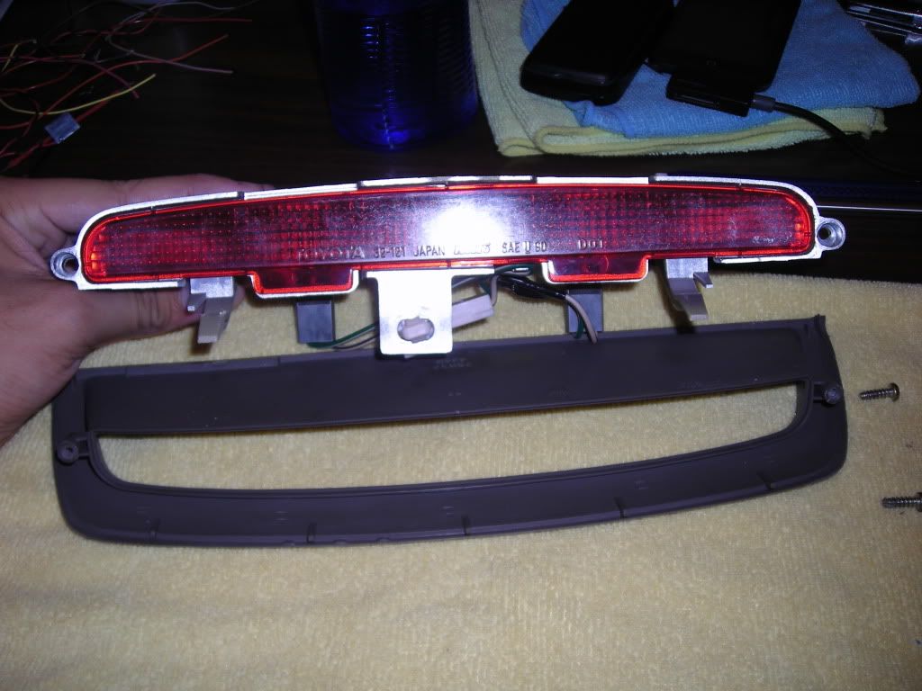
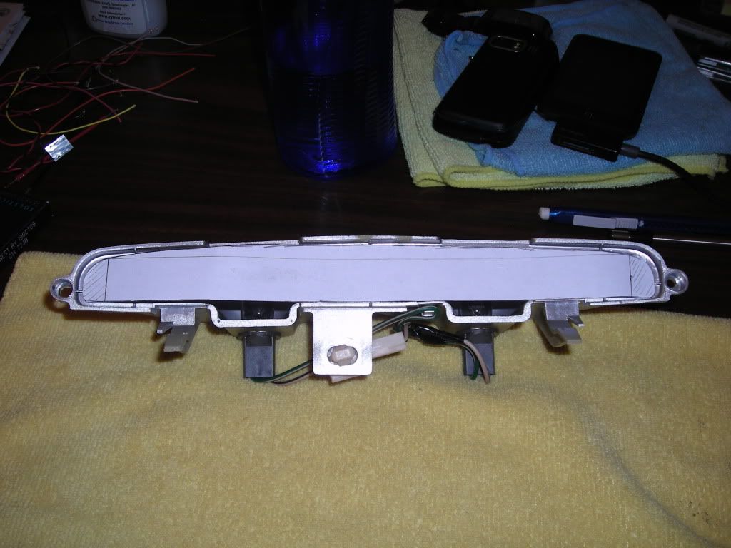
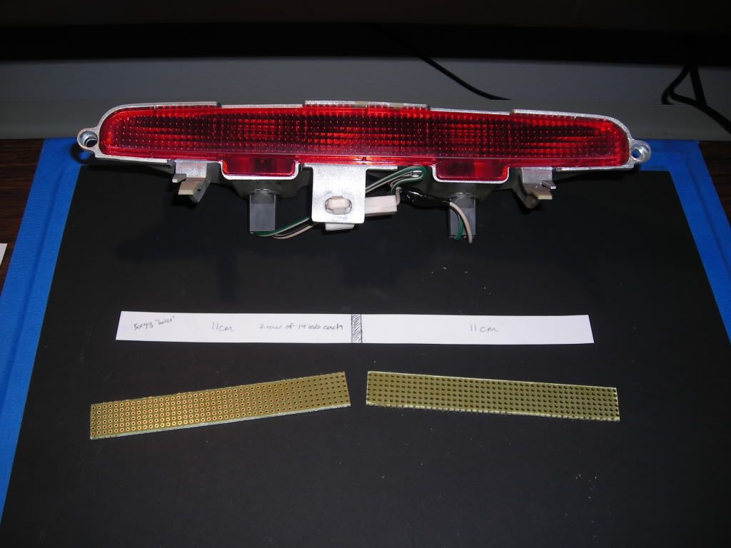
Here is the 3rd brake light taken off using my DIY in this section.
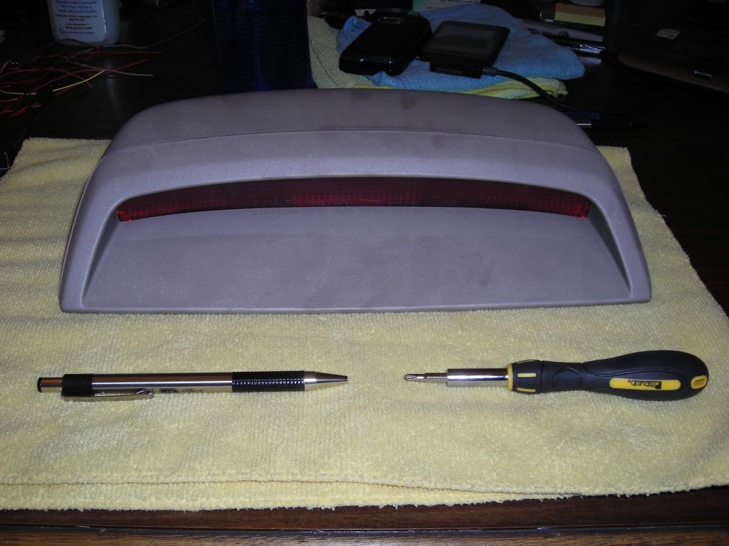
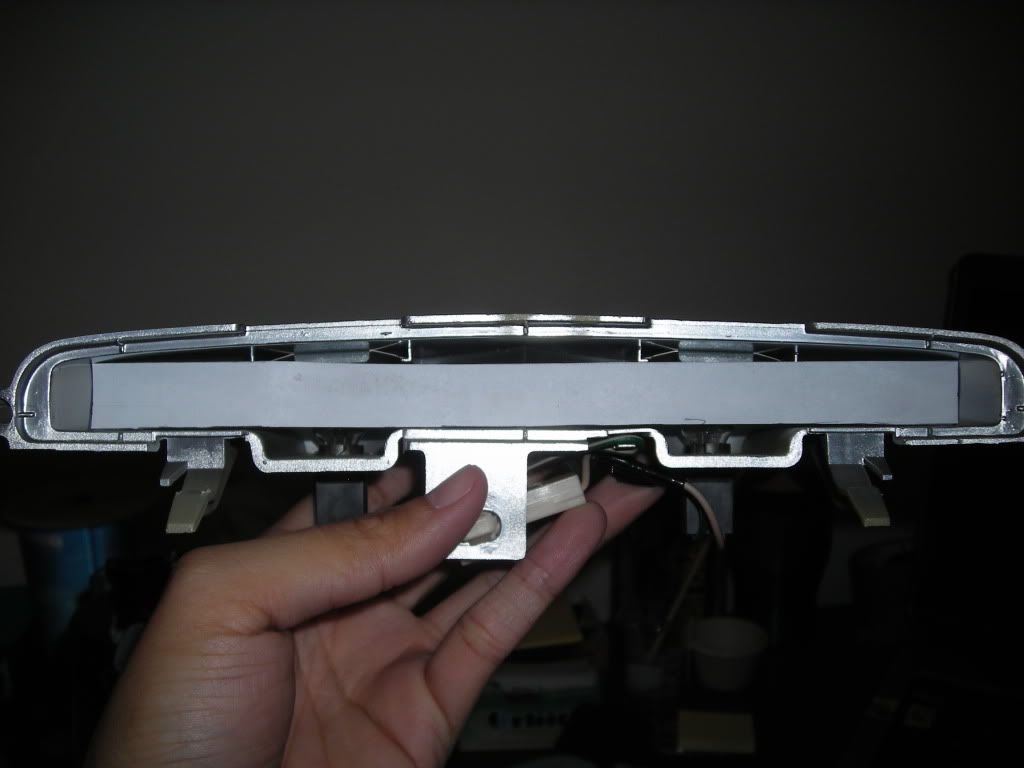
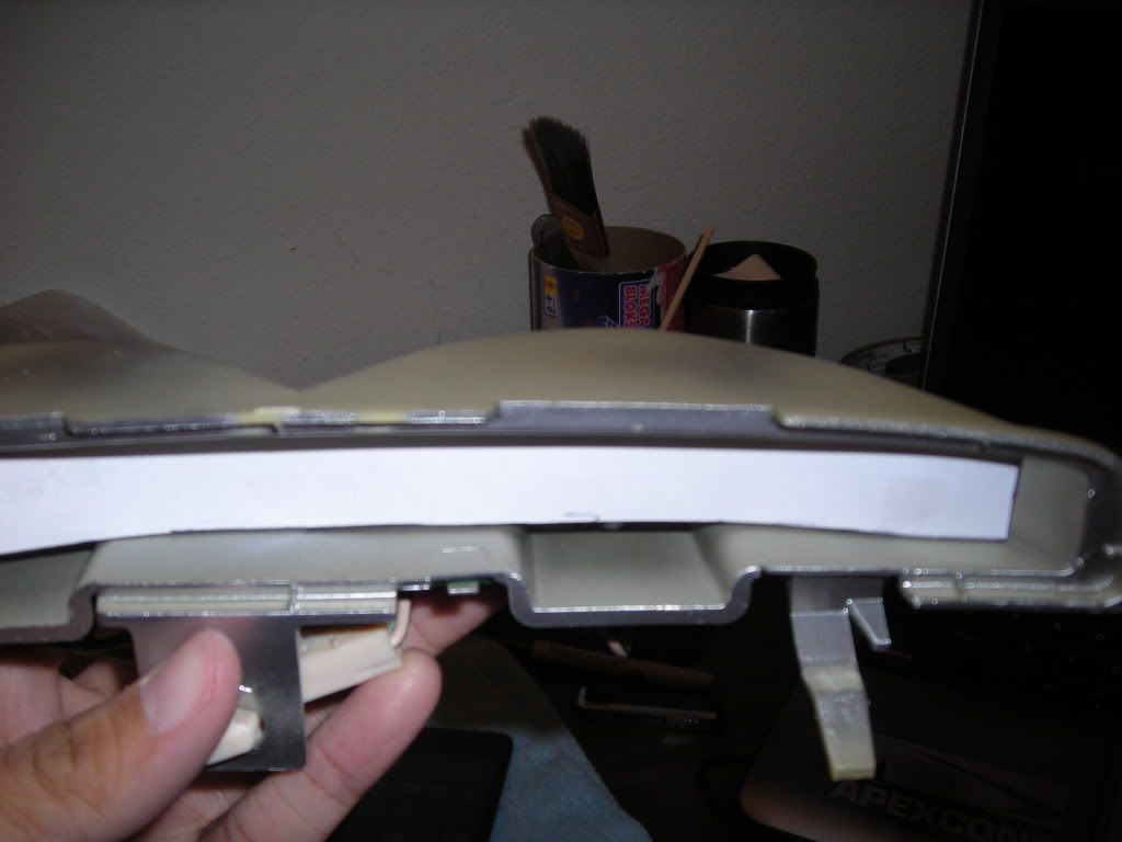
To take apart the housing, the 3 screws at the top must be taken off. Afterwords, it should split into 2 pieces like so.
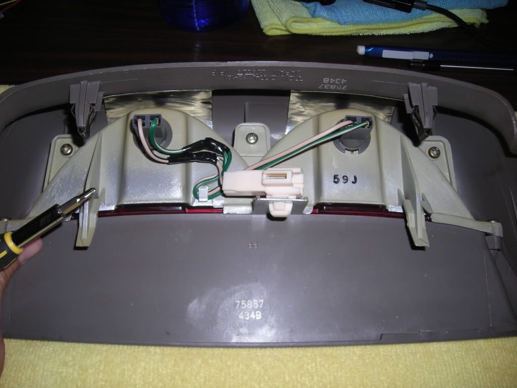
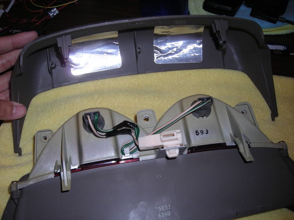
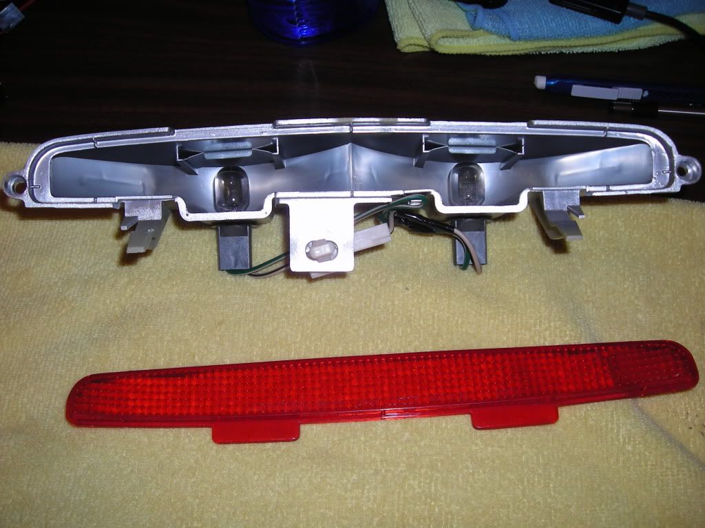
Next up is to take off the 2 remaining screws holding the front of the housing to the part where the bulbs go. Once those are taken off, you can remove the exterior part of the housing and be left with the core.
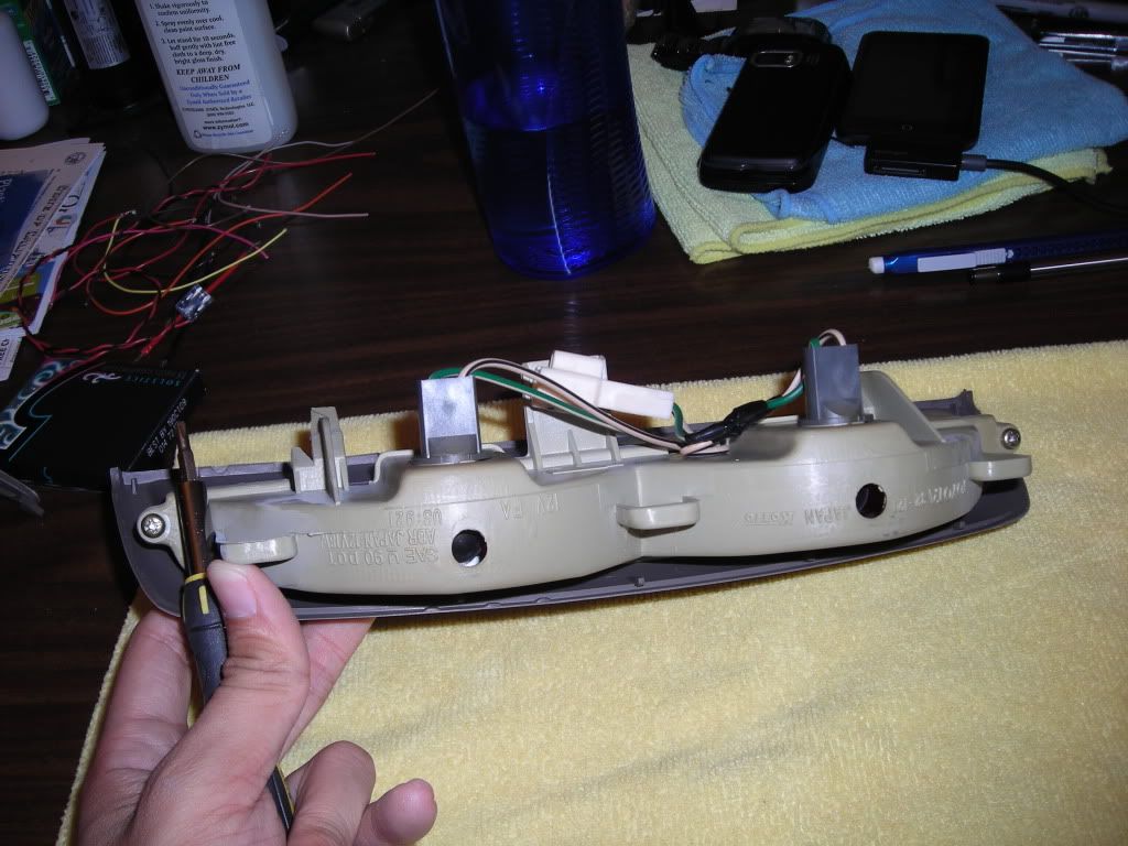
Pretty much, you'll be left with the core piece and the red diffuser just pops out without any effort.
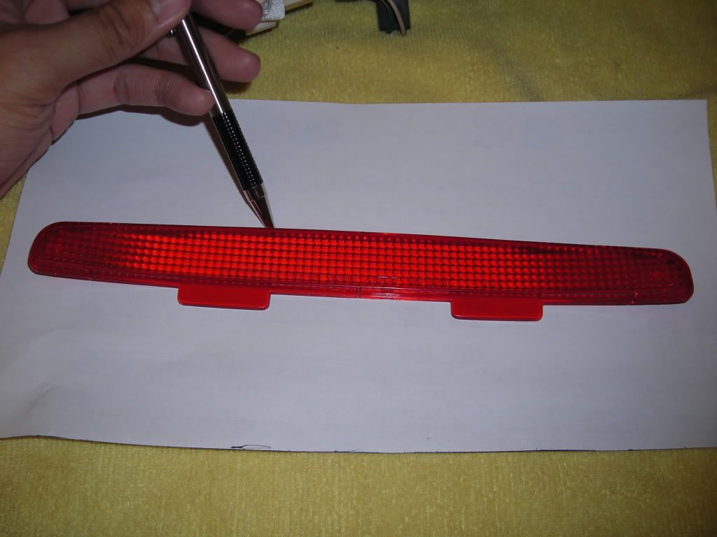
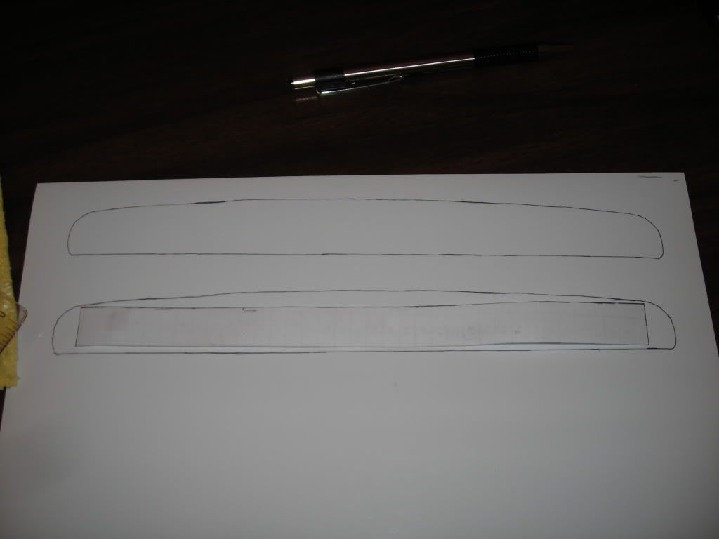
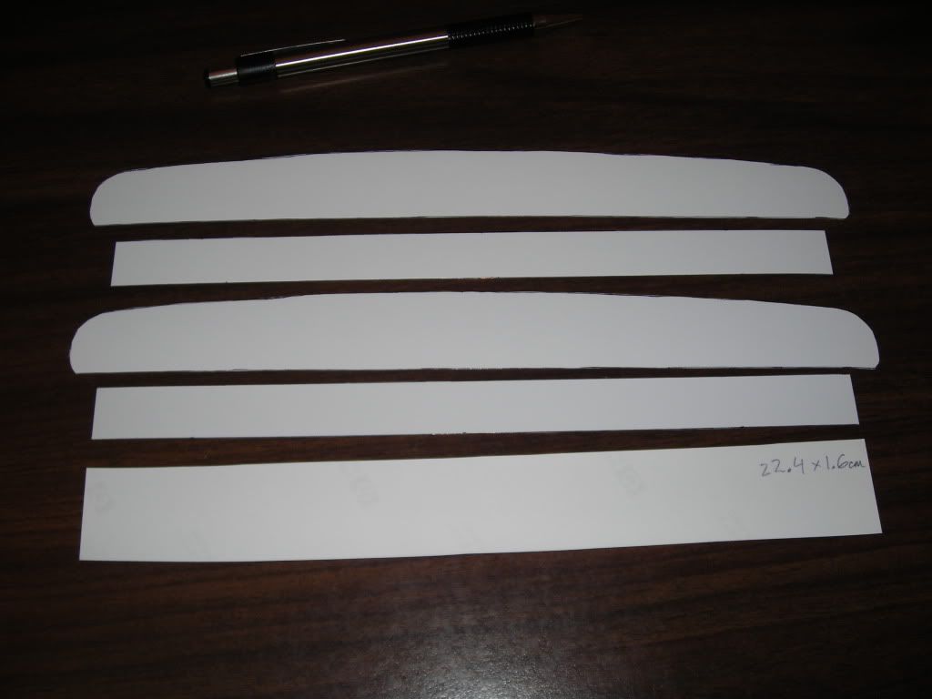
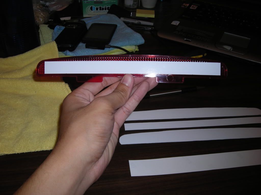
Now to get a rough estimate of how much space I will have to work in there. To get this part, I traced around the plastic red diffuser using a pen and some stiff paper. After, I just cut it out and test fitted it back into the core housing.
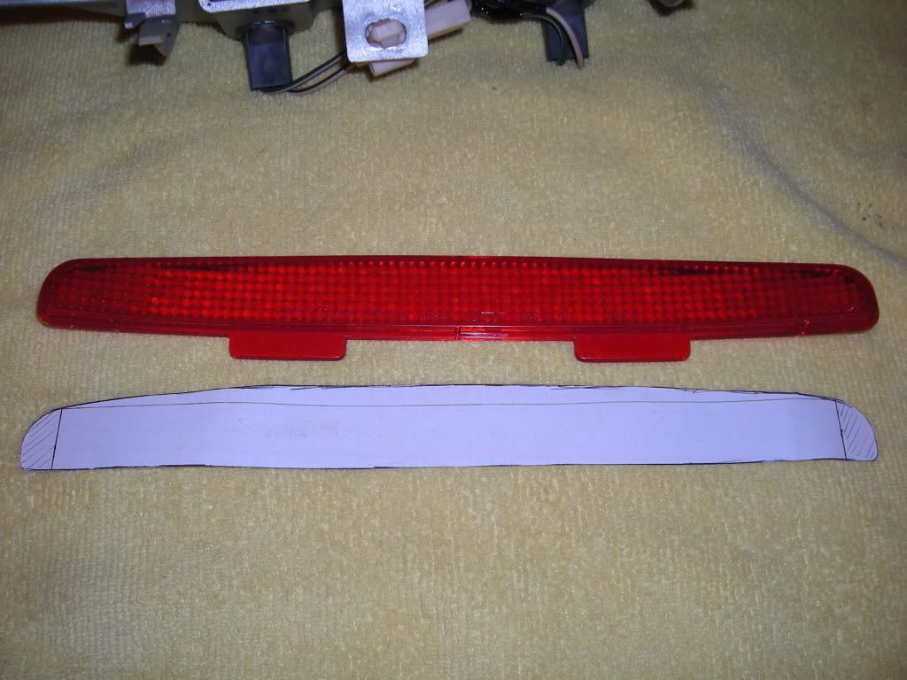
Now that the test fit was successful, I made more copies in case I messed up on the size of the board that will go in there.
Here is the 3rd brake light taken off using my DIY in this section.
To take apart the housing, the 3 screws at the top must be taken off. Afterwords, it should split into 2 pieces like so.
Next up is to take off the 2 remaining screws holding the front of the housing to the part where the bulbs go. Once those are taken off, you can remove the exterior part of the housing and be left with the core.
Pretty much, you'll be left with the core piece and the red diffuser just pops out without any effort.
Now to get a rough estimate of how much space I will have to work in there. To get this part, I traced around the plastic red diffuser using a pen and some stiff paper. After, I just cut it out and test fitted it back into the core housing.
Now that the test fit was successful, I made more copies in case I messed up on the size of the board that will go in there.
Last edited by eyezack87; 06-06-09 at 10:24 PM.
06-06-09, 10:09 PM
#3
Using the trace of the space available in the board, I made rectangles that would fit into the housing that will be a rough sketch of the PCB board with the LEDs soldered into there. Once the test fit of that was done, I also made duplicates.
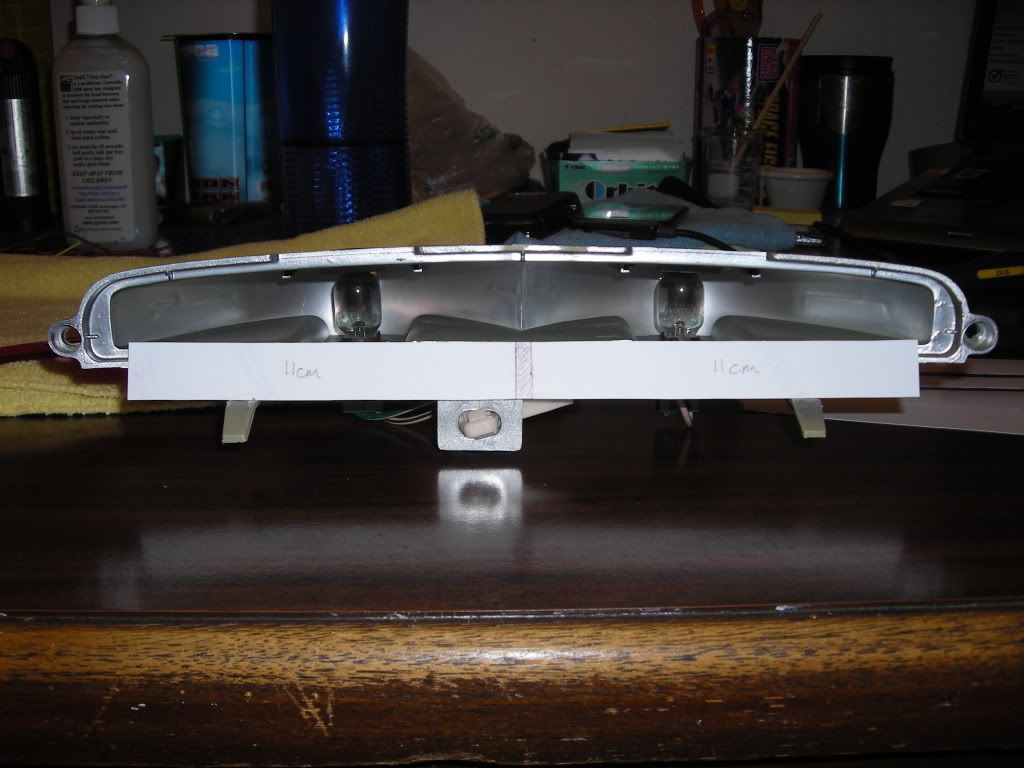
So with the fitted "PCB" board in there, I divided it up into 2 sections, as there were 2 places that I can use to power my circuit board. This, of course, may be changed in the near future as the final concept of mine is not finished yet...
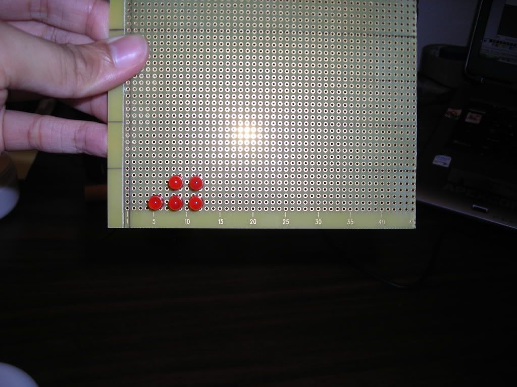
With the appropriate size of the board made, I put the circuit board trace on top of the Prototype board that I will cut to see how much room I will work with (AKA holes)
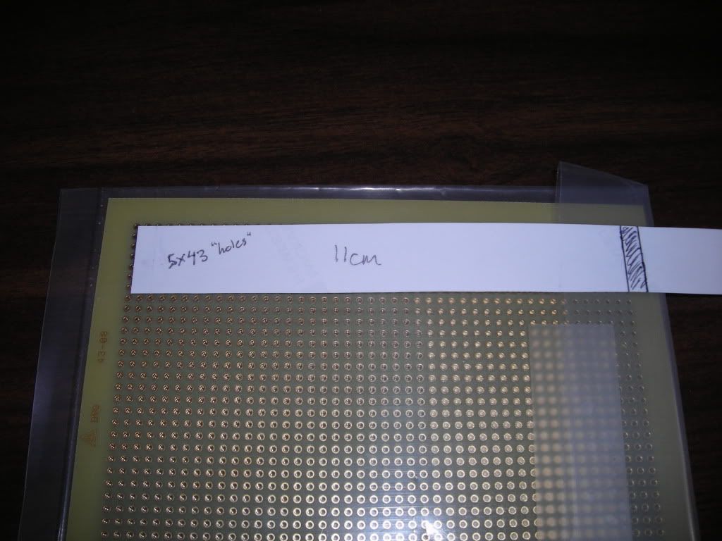
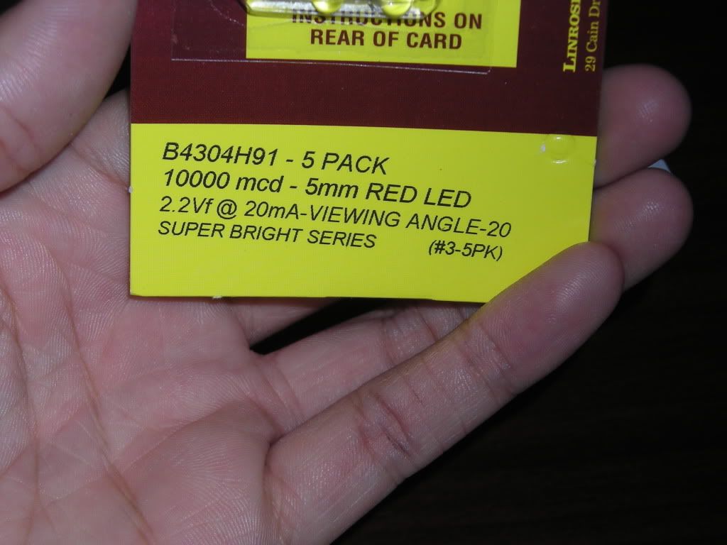
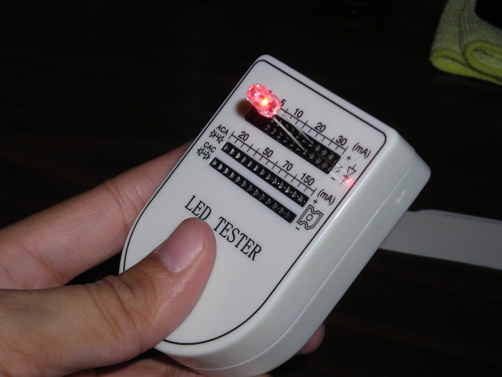
Once that was measured/counted, I decided to use some High Intensity LEDs I had lying around.
Side view
On
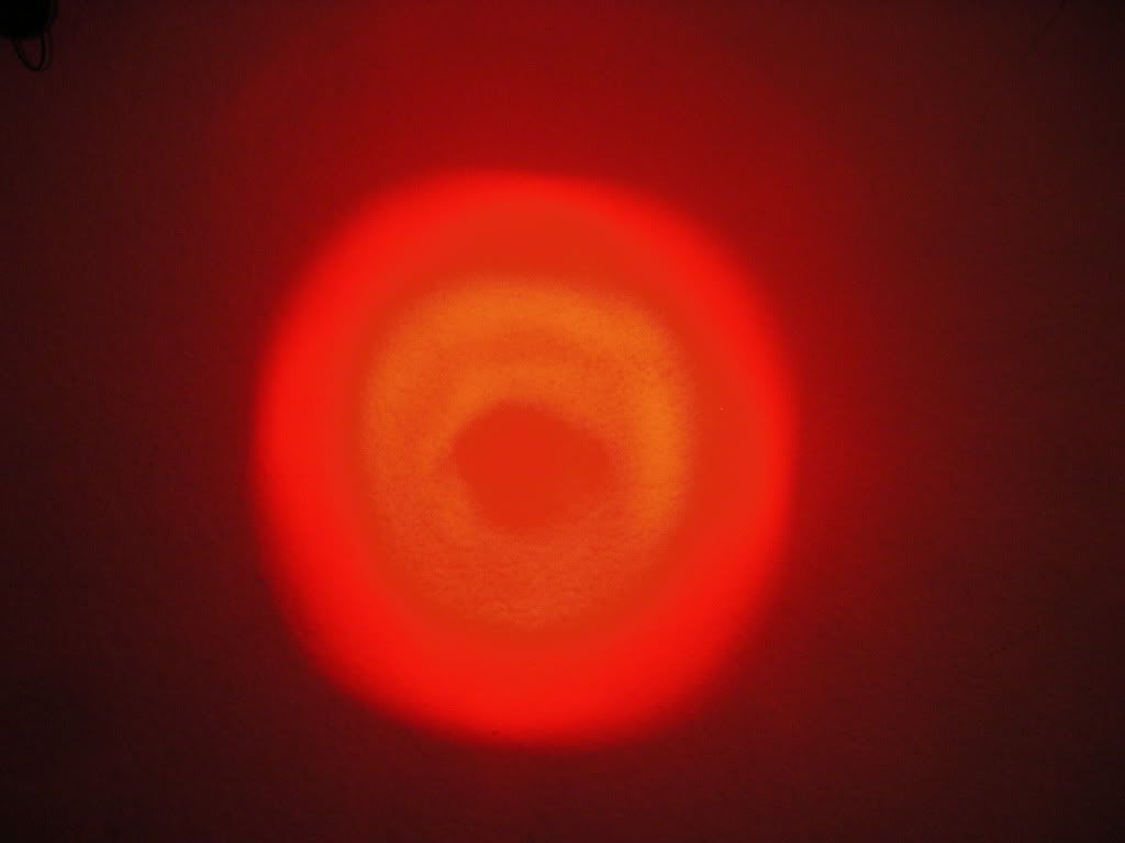
Day shot from 3-4ft away on my wall
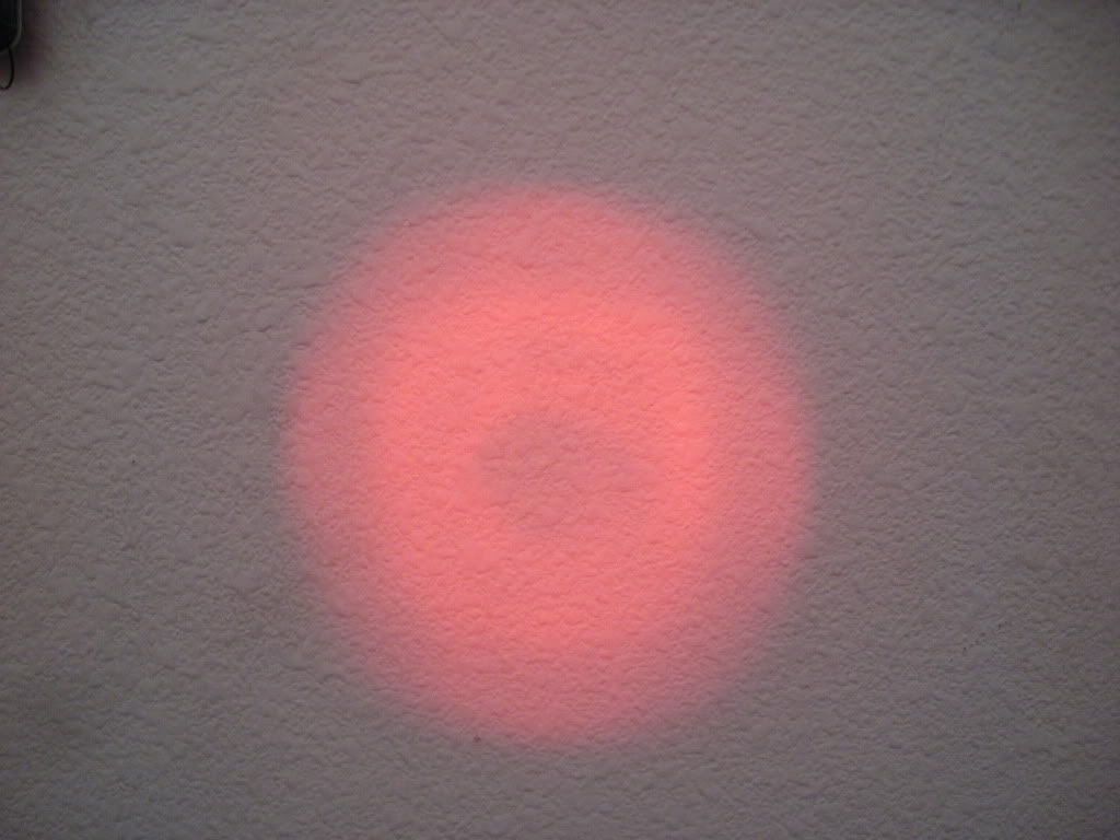
"Night" shot from 3-4ft away on my wall
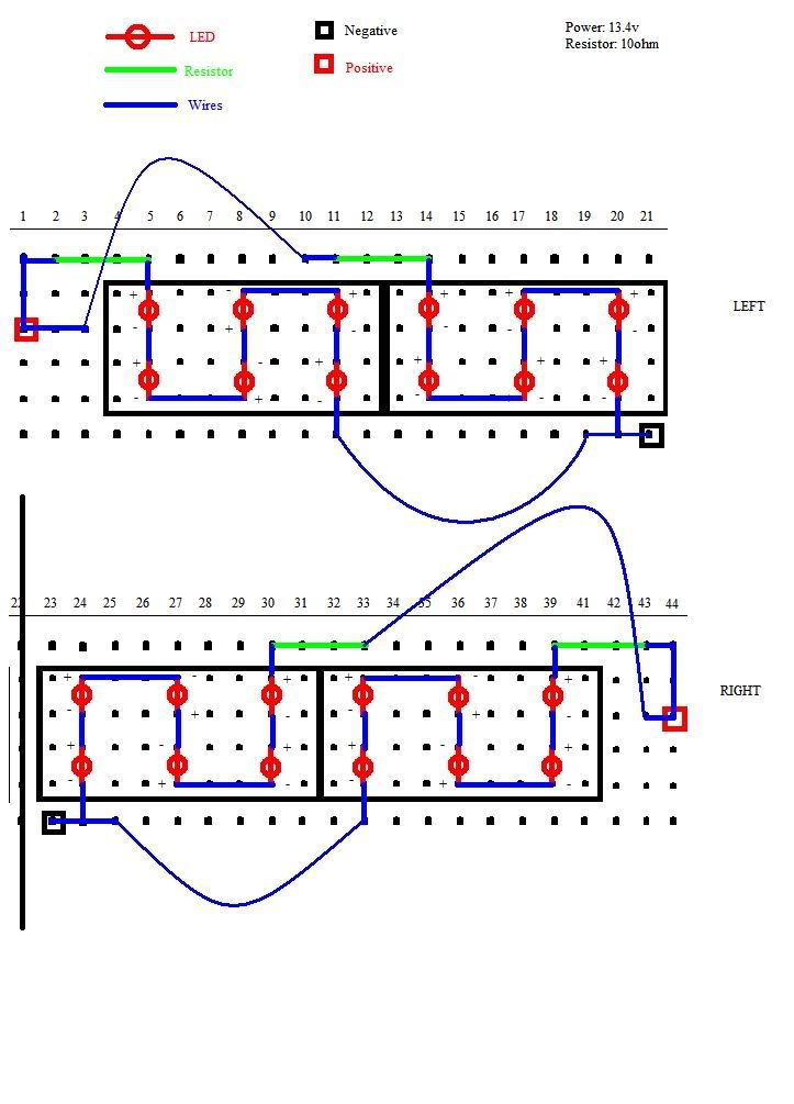
With the LEDs chosen for the brake light, I decided to come up with a simple wiring diagram using Microsoft Paint since I didn't have any real software to do it lol. With that, a mock up using the limited number of LEDs was made. Pretty much, the brake light will consist of 24 High Intensity LEDs, a 2x12 layout with the limited space I had.
So with the fitted "PCB" board in there, I divided it up into 2 sections, as there were 2 places that I can use to power my circuit board. This, of course, may be changed in the near future as the final concept of mine is not finished yet...
With the appropriate size of the board made, I put the circuit board trace on top of the Prototype board that I will cut to see how much room I will work with (AKA holes)
Once that was measured/counted, I decided to use some High Intensity LEDs I had lying around.
Side view
On
Day shot from 3-4ft away on my wall
"Night" shot from 3-4ft away on my wall
With the LEDs chosen for the brake light, I decided to come up with a simple wiring diagram using Microsoft Paint since I didn't have any real software to do it lol. With that, a mock up using the limited number of LEDs was made. Pretty much, the brake light will consist of 24 High Intensity LEDs, a 2x12 layout with the limited space I had.
Last edited by eyezack87; 06-06-09 at 10:40 PM.


Trending Topics
06-07-09, 02:41 PM
#9
So...while in my sleep last night, I realized a way to make the circuit board even more simple with less wires. It was such an easy modification that I kicked myself for making it so complicated in the first place. Update will be up tonight of the new wiring for those who are following 
06-07-09, 02:59 PM
#10
Forum Administrator

iTrader: (2)
Great start Isaac, I'm going to sticky this as you work through it to share with the other ES members!
06-07-09, 09:21 PM
#11
Wow, never expected my thread to be stickied  . Thanks Dave and everyone for the kind comments
--------------
Small update:
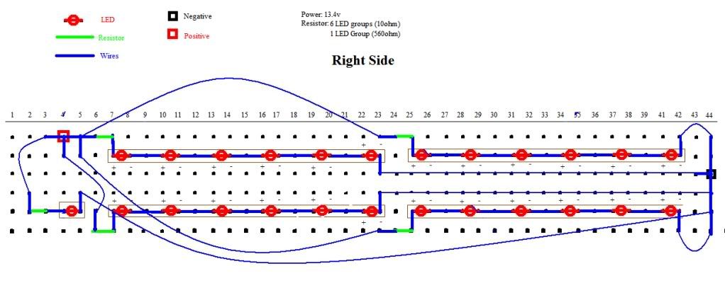
After looking at the schematics, I realized I made a fatal error. So of course, I corrected it and came up with a new half board (mirror image is the other side obviously). Its a bit messy but its all I can think of with my limited knowledge of wiring (forgot all of that unfortunately ). My dad, who IS an EE, refuses to help with this petty project lol. I also added one more LED so it will have a slight slope effect that sorta goes with the shape of the housing, making the total number of LEDs to 25 per half.
I also started cutting up the PCB board. Needless to say, my method of using an Exacto knife to "trace" the line and then using a metal saw takes a while. Thankfully, theres not as much dust as when using a dremel, but I do have to say the dremel is tempting after how long it took to cut the smaller piece of the board off. Pictures of that will be up after I have more light and finish cutting all of it...haha...
And so the wait on the LEDs to come in continues...
. Thanks Dave and everyone for the kind comments --------------
Small update:
After looking at the schematics, I realized I made a fatal error. So of course, I corrected it and came up with a new half board (mirror image is the other side obviously). Its a bit messy but its all I can think of with my limited knowledge of wiring (forgot all of that unfortunately
). My dad, who IS an EE, refuses to help with this petty project lol. I also added one more LED so it will have a slight slope effect that sorta goes with the shape of the housing, making the total number of LEDs to 25 per half.I also started cutting up the PCB board. Needless to say, my method of using an Exacto knife to "trace" the line and then using a metal saw takes a while. Thankfully, theres not as much dust as when using a dremel, but I do have to say the dremel is tempting after how long it took to cut the smaller piece of the board off. Pictures of that will be up after I have more light and finish cutting all of it...haha...
And so the wait on the LEDs to come in continues...
06-12-09, 07:56 PM
#12
So after a LONG wait, my LEDs arrived! So here is an update of my progress. Not as much as I wanted to do but I'm getting better at time management to fit this in. Hope you enjoy this small update!
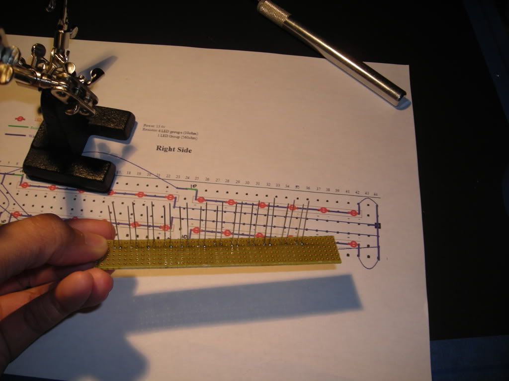
The PCB boards were cut up and fitted according to the paper...
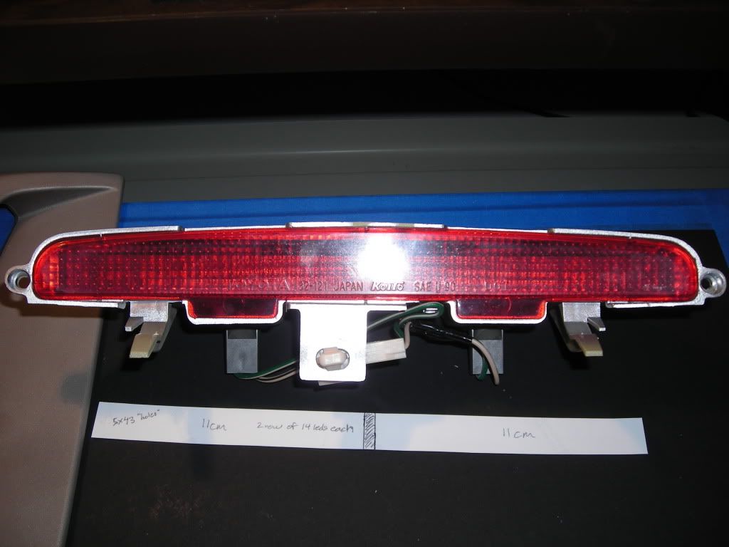
Then fitted into the housing (will be tilted so thats a small change in the original design)
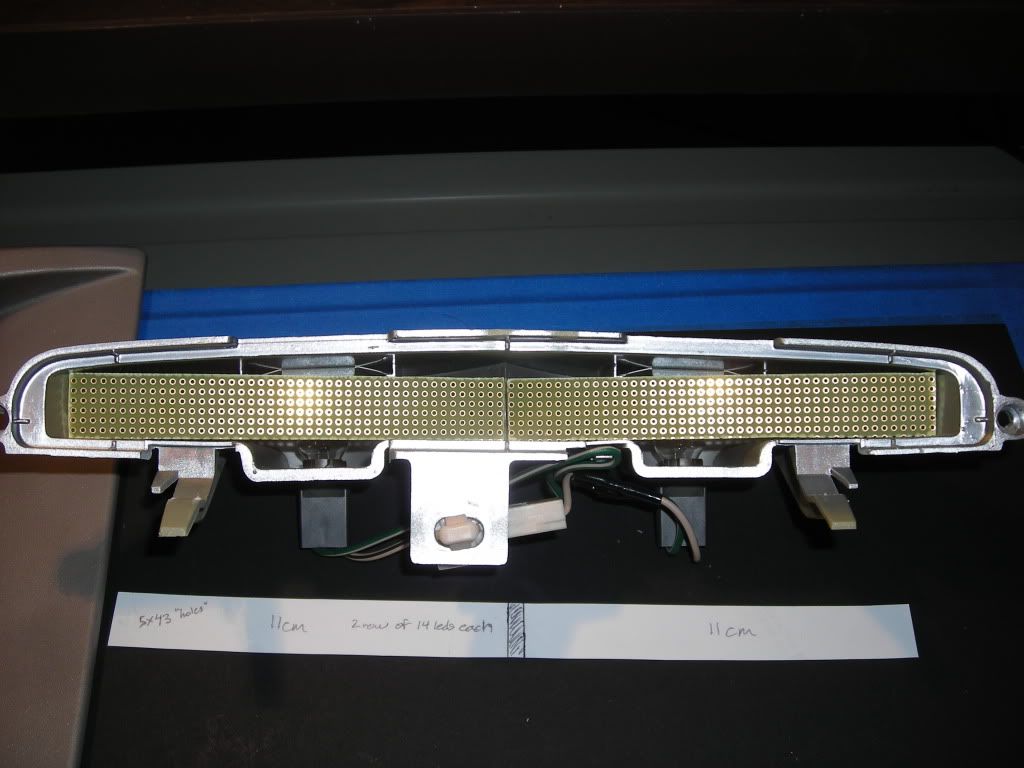
Cover on to make sure it clears it alright...
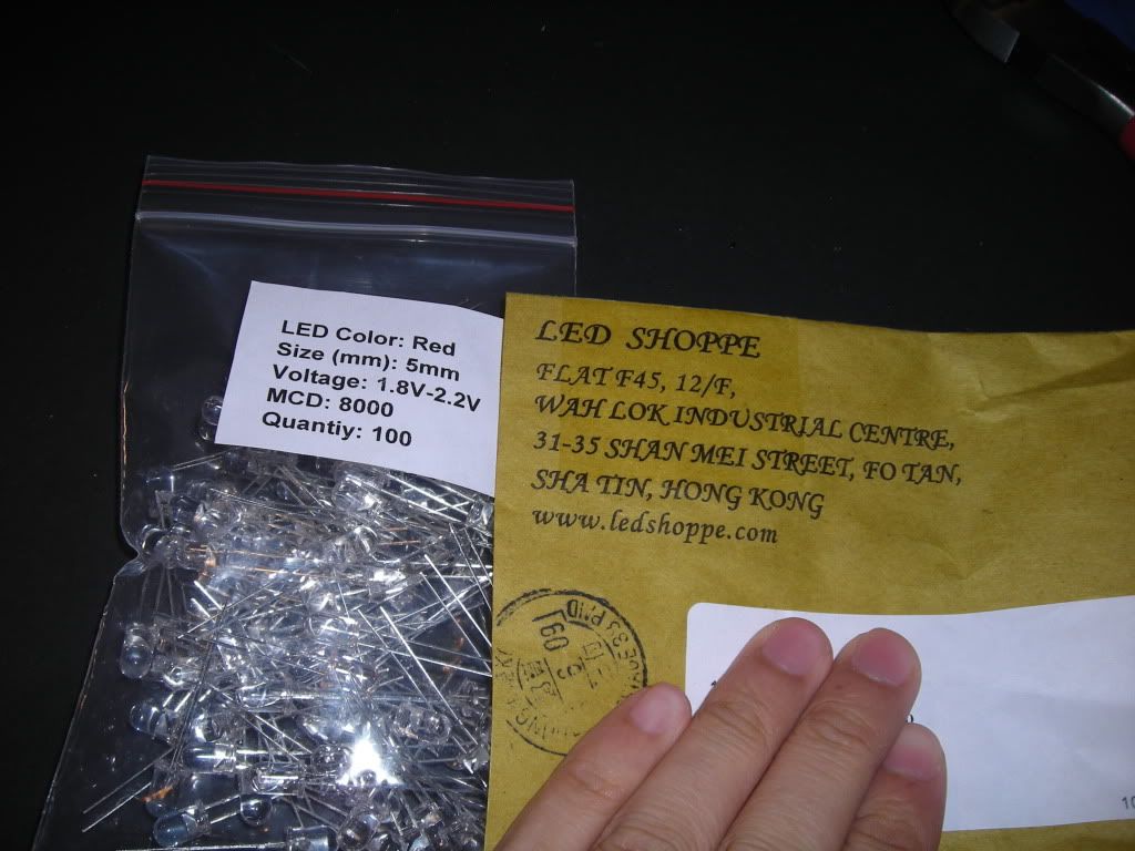
Arrival of LEDs. They're a bit different but they work just fine!
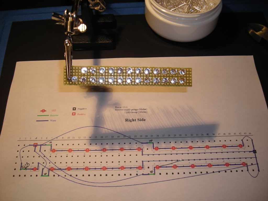
This is what the finished 1/2 board should look like according to my MS Paint schematics
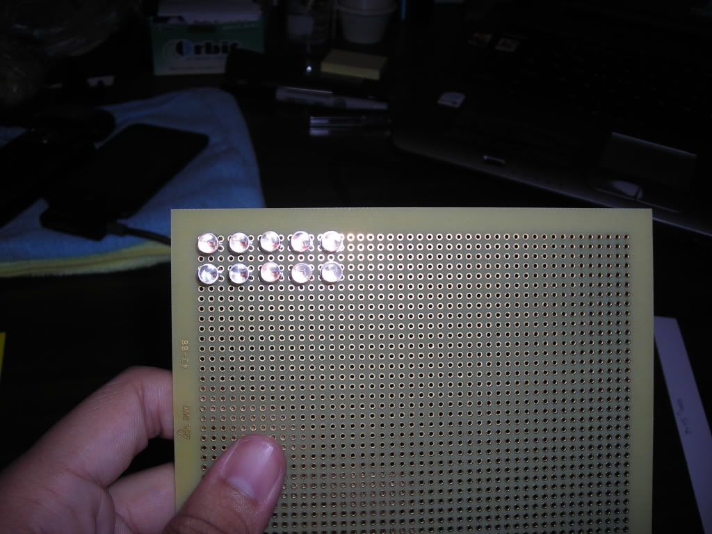
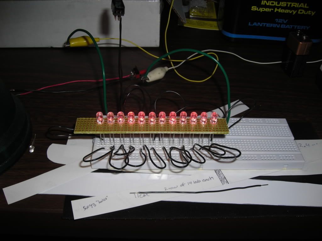
I finished this 1x12 row in about an hour full of distractions (sorry! lol)
Tested on my breadboard with the appropriate resistors and a real 12v lantern battery (flash on)
Tested on breadboard again with flash off
And thats it for now. Keep in mind that the viewing angle isn't that great as I don't really need it to be so its just as bright as the original LEDs if you look at them straight on. Hoped you guys liked this update
The PCB boards were cut up and fitted according to the paper...
Then fitted into the housing (will be tilted so thats a small change in the original design)
Cover on to make sure it clears it alright...
Arrival of LEDs. They're a bit different but they work just fine!
This is what the finished 1/2 board should look like according to my MS Paint schematics
I finished this 1x12 row in about an hour full of distractions (sorry! lol)
Tested on my breadboard with the appropriate resistors and a real 12v lantern battery (flash on)
Tested on breadboard again with flash off
And thats it for now. Keep in mind that the viewing angle isn't that great as I don't really need it to be so its just as bright as the original LEDs if you look at them straight on. Hoped you guys liked this update
06-14-09, 06:16 PM
#13
LED Brake light project is approximately 65% finished!  . Heres a small update of what I have taken pictures of so far...
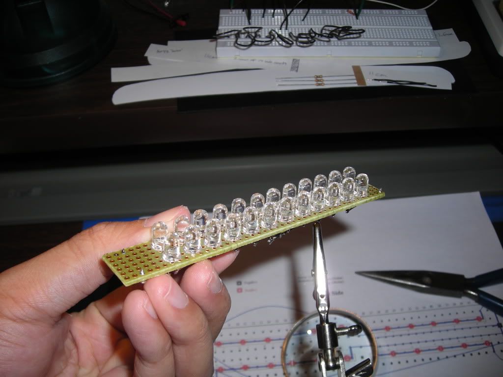
LEDs soldered in first! Messy yes, but as long as it works well I don't mind. It has been 10 years since I touched an iron after all lol...
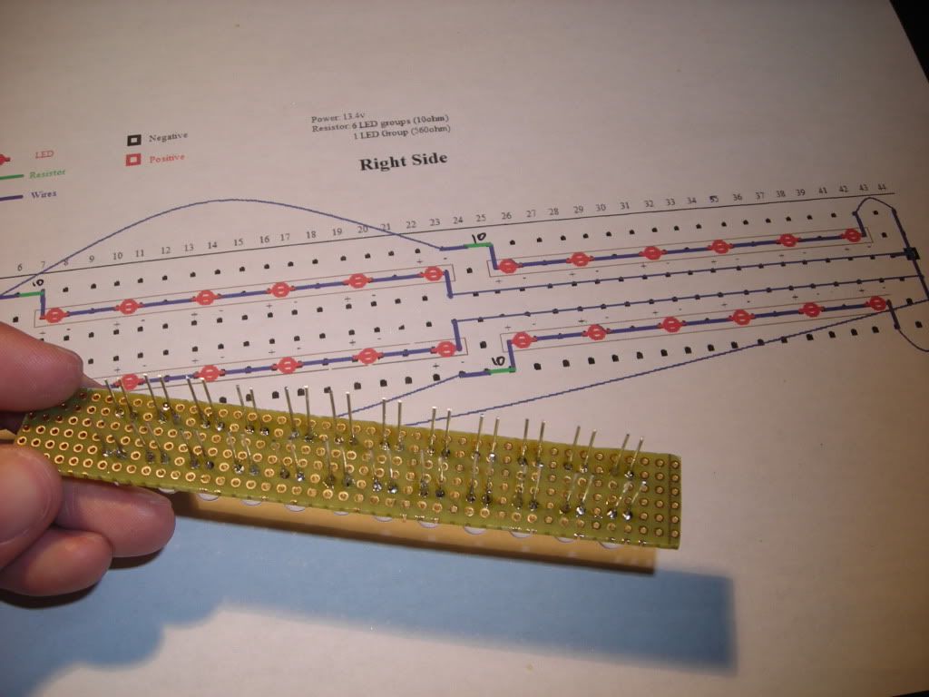
Frontal shot. Modified the original design again due to space. Sorry but its only going to be a 48 LED brake light instead of the proposed 50 LEDs. The 560ohm resistor is very bulky compared to the 10ohm...
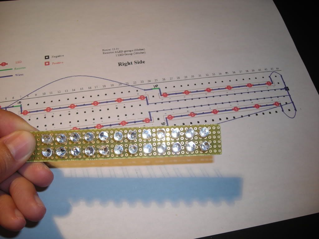
Finished Left half! Everything is soldered on except the power wires, which I will be doing once the Right half is finished.
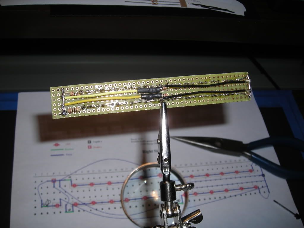
Back side of the Left half. This is as compact as I can get it with my current skill level. Will be test fitting yet again after I cut off the non-functioning holes I'm using as "spacers"
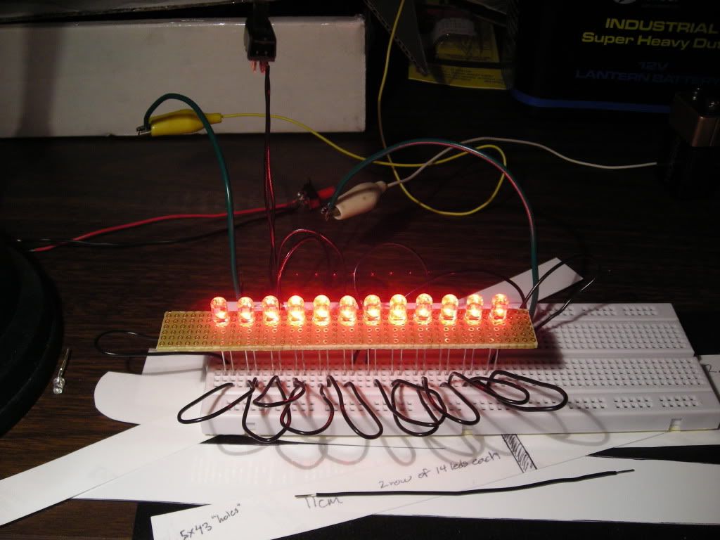
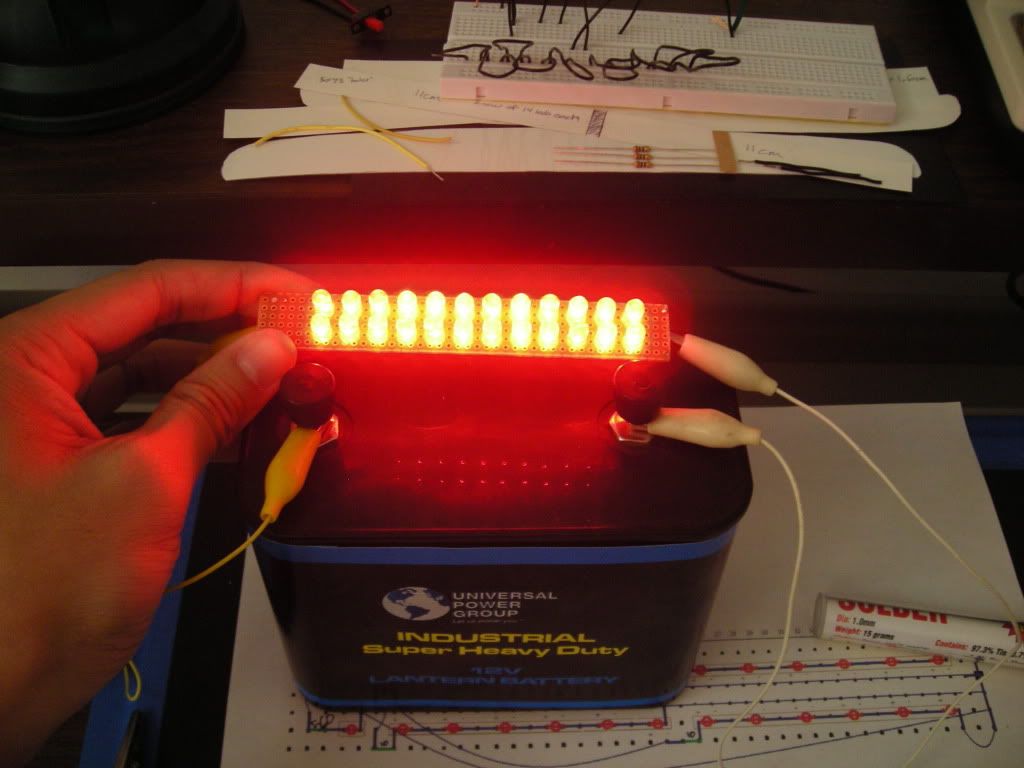
Lit up using a slightly less than 12V battery (sorta had some fun doing other stuff lol....) so it will be brighter when using the full 13.4V that a car would produce. This is the side shot to show how well it fires sideways (remember that LEDs are directional)
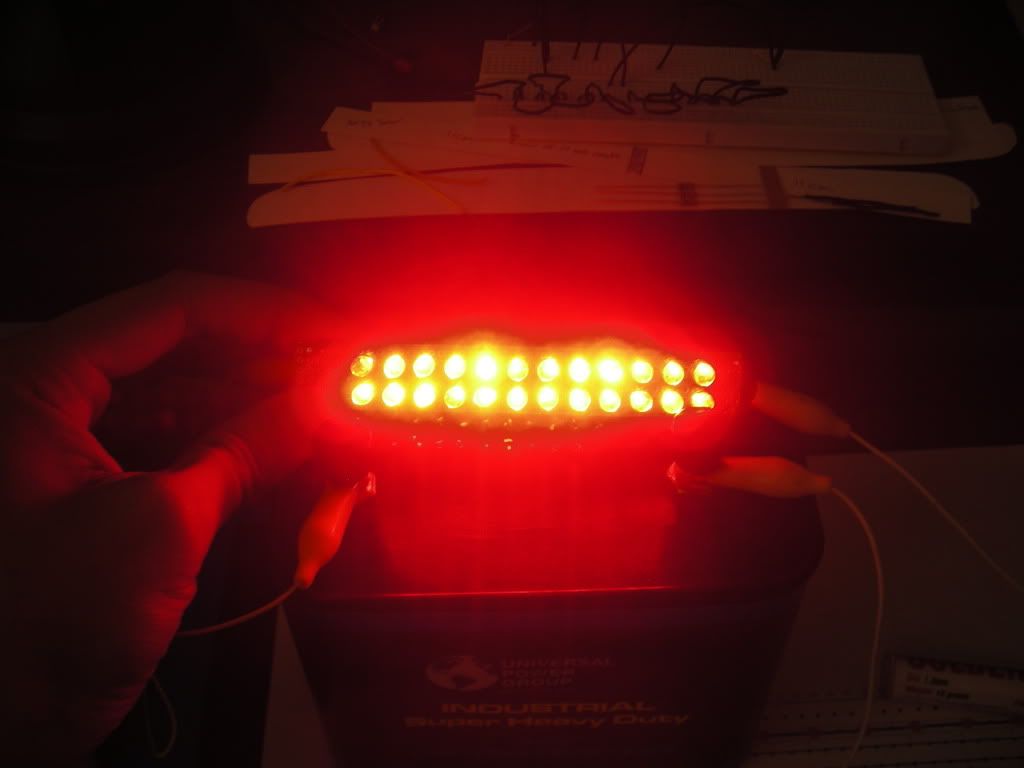
Lit up when viewed almost full on (camera freaked out, as did my eyes when I was trying to position it). Plenty bright for a brake light IMO
Thats it for now. I'll update again once both sides are finished and test fitted
. Heres a small update of what I have taken pictures of so far...LEDs soldered in first! Messy yes, but as long as it works well I don't mind. It has been 10 years since I touched an iron after all lol...
Frontal shot. Modified the original design again due to space. Sorry but its only going to be a 48 LED brake light instead of the proposed 50 LEDs. The 560ohm resistor is very bulky compared to the 10ohm...
Finished Left half! Everything is soldered on except the power wires, which I will be doing once the Right half is finished.
Back side of the Left half. This is as compact as I can get it with my current skill level. Will be test fitting yet again after I cut off the non-functioning holes I'm using as "spacers"
Lit up using a slightly less than 12V battery (sorta had some fun doing other stuff lol....) so it will be brighter when using the full 13.4V that a car would produce. This is the side shot to show how well it fires sideways (remember that LEDs are directional)
Lit up when viewed almost full on (camera freaked out, as did my eyes when I was trying to position it). Plenty bright for a brake light IMO
Thats it for now. I'll update again once both sides are finished and test fitted
 06-15-09, 09:01 PM
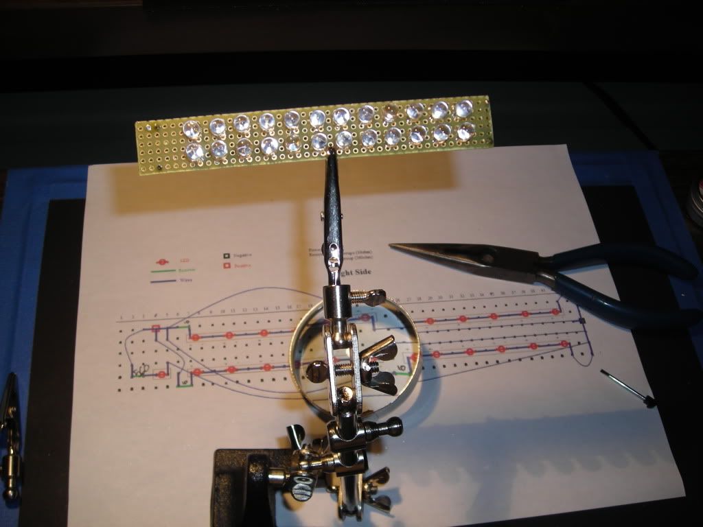
#15
I made each LED attached to one another in an "L" shape so it can be easily desoldered and replaced. All I need to do is remove or heat up the solder joint at the place where the pos and neg pieces connect, snip off the solder parts, and then heat the base of the joint on the circuit board to easily pull it off. Its the same thing with the resistors, each one is simple to remove unlike my first version that I gave up on (millions of flaws in that one lol)