Road to a Time Attack Soarer

Pole Position


Joined: Feb 2012
Posts: 2,392
Likes: 1,219
From: CO
Excellent - I can't wait to see more! My wife and I both went through engineering school and she actually teaches HS level engineering these days. They're just now learning on 3D printers and moving onto scanners soon. So cool that this technology is finally accessible to people like us!

Thread Starter
Instructor

Joined: May 2007
Posts: 1,001
Likes: 64
From: ca
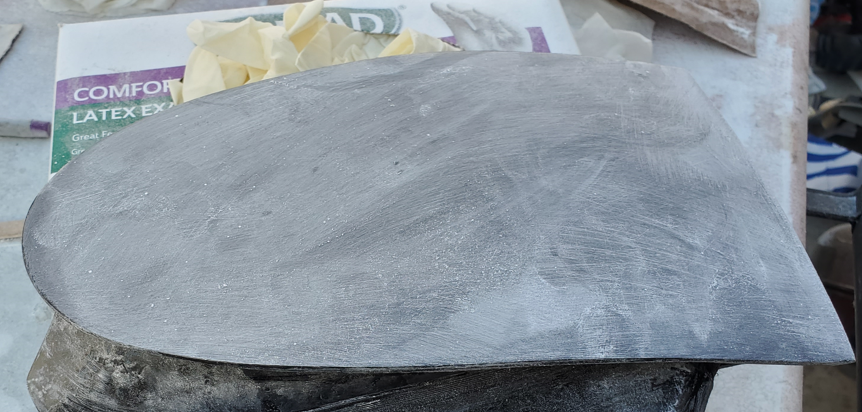
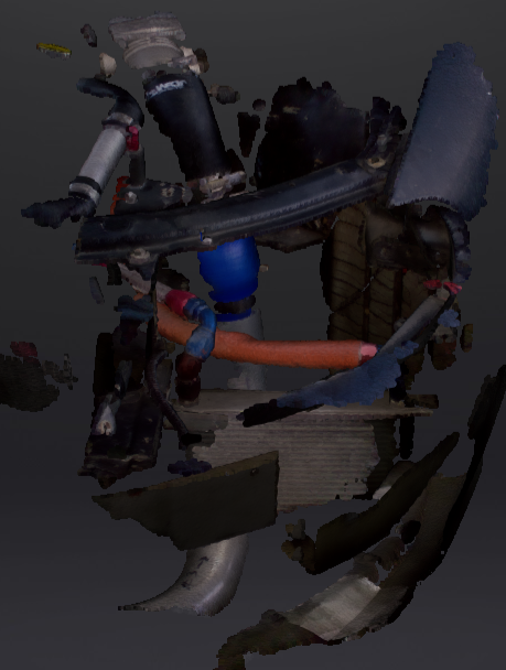
I started working on my oil cooler duct.
I 3D scanned the cooler area, and I'm gonna use that to guide my CAD.
Had to spray a lot of baby powder on my newly painted bumper since scanners don't do well with black surfaces.
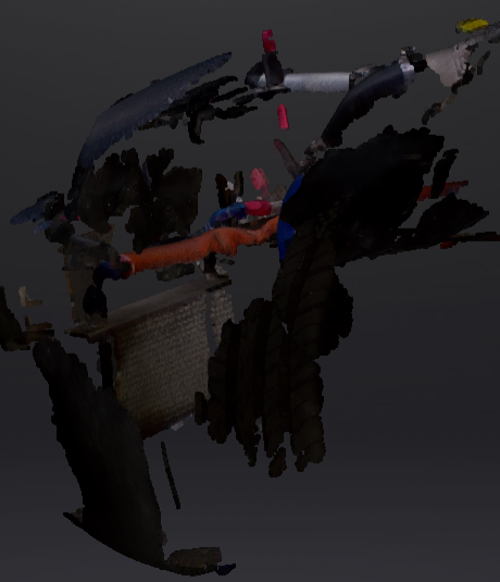
Here's what it looks like when in CAD

I 3D scanned the cooler area, and I'm gonna use that to guide my CAD.
Had to spray a lot of baby powder on my newly painted bumper since scanners don't do well with black surfaces.
Here's what it looks like when in CAD
Thread Starter
Instructor
Joined: May 2007
Posts: 1,001
Likes: 64
From: ca
Been working off and on the intercooler-radiator ducting. Just used 1/16 ABS and went to town. I think the fitment is as good as it's gonna get. I plan on using seals and foam to seal some areas. Sorry my engine bay is a mess at the moment.


Alright... Does anyone have input on a good way to hang the intercooler? I have these "ghetto" straps you see above. They worked great but I hate the way they look lol I had beams in the bottom before, but they hit the ground the first driveway I went over. They also bent by radiator support ehhh. So The straps work great because they allow the intercooler some compliance in case of I hit something. Input is appreciated.
Here's something else I've been working on. I decided on taking out the high beams and using this opening to feed fresh air to the radiator by a duct. The area fed from the high beam openings will be separated from the intercooler area by a divider (shown above). I 3d scanned the area and designed the duct you see below.

I then decided on stiffening it a bit with carbon fiber. It was kinda difficult since I couldn't use vacuum bagging easily, and I really didn't wanna make a meal out of it. So I wet-layed it. I don't like the quality but it's "good enough". Now, I've had the Duratec stuff for a while and have not used (UV protection). So I decided to try it out on the ducts. This stuff was not easy to work with. I thought it laid like clear coat. Boy was I wrong! It took me 2 tries to find the right nozzle/gun combination. I trashed the material both times since pot life is like 10 minutes. It's drying as we speak.
I'm going to use my gelcoat gun next time to spray this stuff. I'm hoping to be able to spray it on my sunroof delete panel and prevent from yellowing.
No, they did not come with the booster seat!


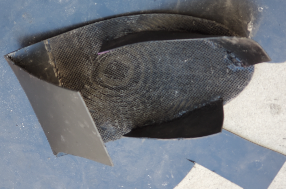
A few weeks ago, I started looking into putting strakes or guides on my hood vents. I designed them in CAD and 3d printed a template then made the composite parts. I just finished attaching them to the vents.


These were vacuum bagged.

Dry look for now... I think I like it.

Alright... Does anyone have input on a good way to hang the intercooler? I have these "ghetto" straps you see above. They worked great but I hate the way they look lol I had beams in the bottom before, but they hit the ground the first driveway I went over. They also bent by radiator support ehhh. So The straps work great because they allow the intercooler some compliance in case of I hit something. Input is appreciated.
Here's something else I've been working on. I decided on taking out the high beams and using this opening to feed fresh air to the radiator by a duct. The area fed from the high beam openings will be separated from the intercooler area by a divider (shown above). I 3d scanned the area and designed the duct you see below.
I then decided on stiffening it a bit with carbon fiber. It was kinda difficult since I couldn't use vacuum bagging easily, and I really didn't wanna make a meal out of it. So I wet-layed it. I don't like the quality but it's "good enough". Now, I've had the Duratec stuff for a while and have not used (UV protection). So I decided to try it out on the ducts. This stuff was not easy to work with. I thought it laid like clear coat. Boy was I wrong! It took me 2 tries to find the right nozzle/gun combination. I trashed the material both times since pot life is like 10 minutes. It's drying as we speak.
I'm going to use my gelcoat gun next time to spray this stuff. I'm hoping to be able to spray it on my sunroof delete panel and prevent from yellowing.
No, they did not come with the booster seat!
A few weeks ago, I started looking into putting strakes or guides on my hood vents. I designed them in CAD and 3d printed a template then made the composite parts. I just finished attaching them to the vents.
These were vacuum bagged.
Dry look for now... I think I like it.
Thread Starter
Instructor
Joined: May 2007
Posts: 1,001
Likes: 64
From: ca
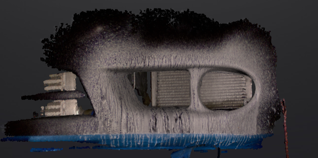
Been tinkering with the oil cooler duct design a bit. Used the 3D scan point cloud/mesh to guide my CAD. This will be feeding a 6x11" cooler on the driver side.
Below is the front view (looking at the left side of the bumper). The plan is to use the opening on the left. Eventually, I'm planning on designing something to block the opening on the right.

View from the right.

View from above.

Just the duct.


I'm hoping to print it in sections, glue them, then pad it with some carbon.
Below is the front view (looking at the left side of the bumper). The plan is to use the opening on the left. Eventually, I'm planning on designing something to block the opening on the right.
View from the right.
View from above.
Just the duct.
I'm hoping to print it in sections, glue them, then pad it with some carbon.
Thread Starter
Instructor
Joined: May 2007
Posts: 1,001
Likes: 64
From: ca


Thread Starter
Instructor
Joined: May 2007
Posts: 1,001
Likes: 64
From: ca
Last Post (Continued)...
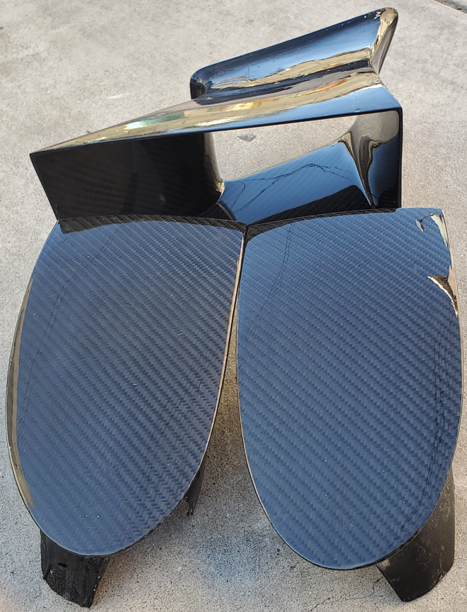
Overall, I'm pleased with the way they came out. However, they did take me a lot more time to make than I ever wanted to. Looking at them, there's no indication of how much work went in to making them lol
I'm going to document the process in case if anyone is curious.
After I designed the oil cooler duct, I proceeded to 3d printing that. Since I have a hobbyist printer, with enough bed surface to print small things, I had to break my print to 10 different prints...
Took 2 weeks to print...
What a nightmare!
Then, I had to line them all up (correctly if I might add) then weld them together. Using only 2 hands here!


After I was all done, I went to test fit, I realized I made a mistake on the CAD and my outlet was 7" high instead of 6"....... AAAAAAAAAAAAAAAAAAAAAAAAAAAAAAAAAAAAAAAAAAAAAAAAAAAAAAAAAAH
I know I wanted to check that dimension before printing... Just got side tracked by something ( I blame my kids)...
I fixed the error and repeated the process... this time it fit.
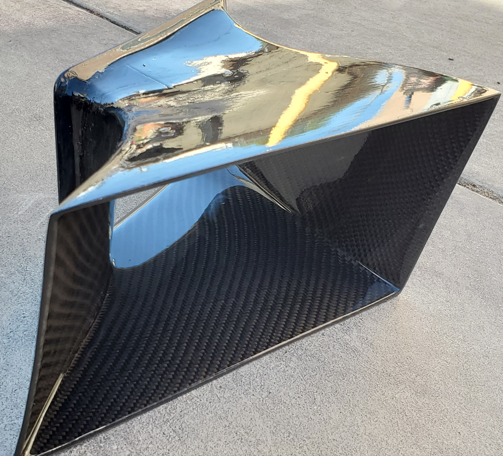
I also added a funnel shaped entry to facilitate bumper cover installation.
How it looks on the bumper cover.


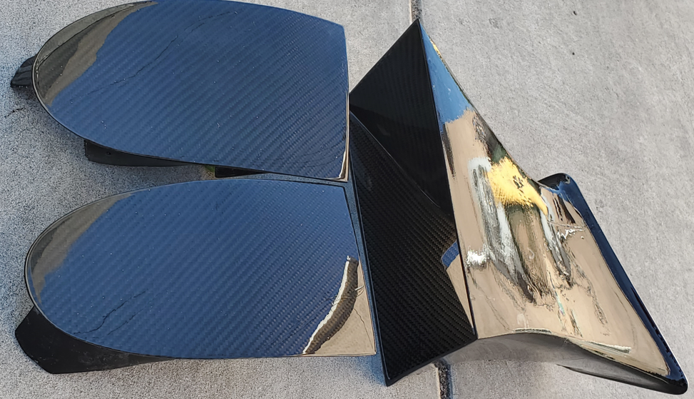
Now it's time for reinforcement.
Fitting a continuous fabric to this shape is not the easiest.


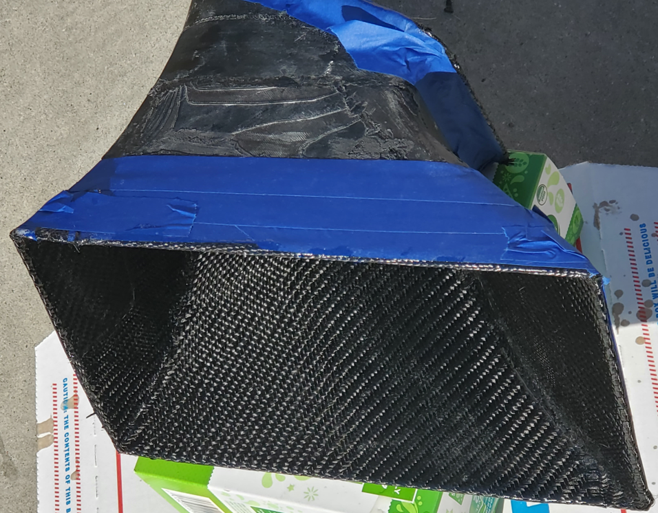
Then wet-layup...
Wet layup is the worst method to make any composite part. I really didn't wanna make a mold then vacuum-bag it. But I think I lost a lot more time doing it the wet-layup method.

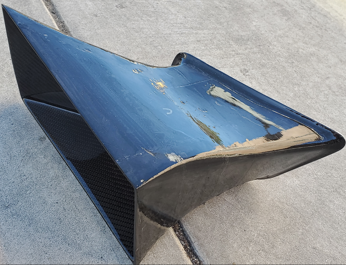
Then came sanding...
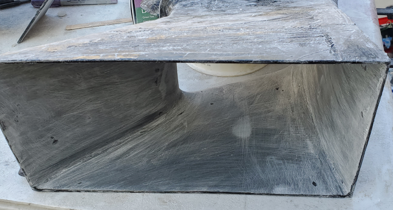
Then DURATEC sunshield clearcoat, then more sanding, and more sanding.... Then more sanding...Then clearcoat...
Overall, I'm pleased with the way they came out. However, they did take me a lot more time to make than I ever wanted to. Looking at them, there's no indication of how much work went in to making them lol
I'm going to document the process in case if anyone is curious.
After I designed the oil cooler duct, I proceeded to 3d printing that. Since I have a hobbyist printer, with enough bed surface to print small things, I had to break my print to 10 different prints...
Took 2 weeks to print...
What a nightmare!
Then, I had to line them all up (correctly if I might add) then weld them together. Using only 2 hands here!
After I was all done, I went to test fit, I realized I made a mistake on the CAD and my outlet was 7" high instead of 6"....... AAAAAAAAAAAAAAAAAAAAAAAAAAAAAAAAAAAAAAAAAAAAAAAAAAAAAAAAAAH
I know I wanted to check that dimension before printing... Just got side tracked by something ( I blame my kids)...
I fixed the error and repeated the process... this time it fit.
I also added a funnel shaped entry to facilitate bumper cover installation.
How it looks on the bumper cover.
Now it's time for reinforcement.
Fitting a continuous fabric to this shape is not the easiest.
Then wet-layup...
Wet layup is the worst method to make any composite part. I really didn't wanna make a mold then vacuum-bag it. But I think I lost a lot more time doing it the wet-layup method.
Then came sanding...
Then DURATEC sunshield clearcoat, then more sanding, and more sanding.... Then more sanding...Then clearcoat...
Thread Starter
Instructor
Joined: May 2007
Posts: 1,001
Likes: 64
From: ca
Continued...

I have to wait a couple of days for the clear coat to cure a bit more.
I can't wait to try it on the oil cooler and put the bumper on.
I plan on putting a weather seal on the edges against the cooler. I'm thinking of hard mounting the duct to the oil cooler instead of leaving it floating... OR... wait till I make the exit duct then connecting the 2, and essentially sandwiching the cooler. TBD
Thread Starter
Instructor
Joined: May 2007
Posts: 1,001
Likes: 64
From: ca
Continued
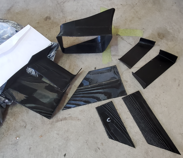
Now for the fog light delete panels...
I initially designed it in CAD, printed the design, tried on the bumper, then realized extending it will better seal the air going to the oil cooler. It essentially prevents the air from backing up and escaping from the fog light hole.
You can see the extension here.

You can see where air would escape here... More work to be done..

I needed to add another piece to block that escape route.
Took a few tries to get it just right... 3 failed attempts.

Then I added 2 more pieces to mount the panel to the inside of the bumper. A lot of trial and error here.

It looked like this:


Time to level the surface. Body filler and black die.

Curing
Can You guess what's coming?
You guessed it... SANDING

To be continued...
Now for the fog light delete panels...
I initially designed it in CAD, printed the design, tried on the bumper, then realized extending it will better seal the air going to the oil cooler. It essentially prevents the air from backing up and escaping from the fog light hole.
You can see the extension here.
You can see where air would escape here... More work to be done..
I needed to add another piece to block that escape route.
Took a few tries to get it just right... 3 failed attempts.
Then I added 2 more pieces to mount the panel to the inside of the bumper. A lot of trial and error here.
It looked like this:
Time to level the surface. Body filler and black die.
Curing
Can You guess what's coming?
You guessed it... SANDING
To be continued...
Thread Starter
Instructor
Joined: May 2007
Posts: 1,001
Likes: 64
From: ca
Continued...
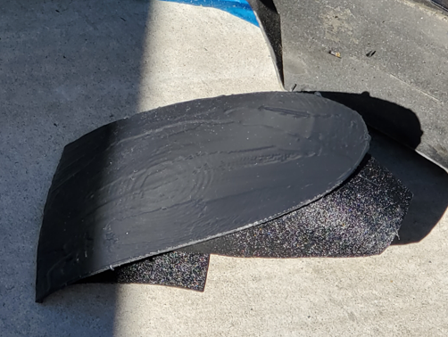
Reinforcement...

Wet layup.... Unfortunately...


Right side... I opted to replicate the process I followed with the driver side.


More sanding

Measuring up fabric


Wet layup..

Excess resin...

Reinforcement...
Wet layup.... Unfortunately...
Right side... I opted to replicate the process I followed with the driver side.
More sanding
Measuring up fabric
Wet layup..
Excess resin...