When you click on links to various merchants on this site and make a purchase, this can result in this site earning a commission. Affiliate programs and affiliations include, but are not limited to, the eBay Partner Network.
This had to be done in order to get my NA fuel pump out. I had originally planned to drive with the old engine until the fuel level got down to 1/4 or less but problems arose before that could happen.
From 3/4 of a tank (from the full 20.6 gallon capacity) I was able to get my gas tank down to 1/2 full using a fuel-rated $15 plunger style hand pump. After that I couldn't seem to get ANY more fuel out of it no matter what I did.
Not being keen on jacking up the car and loosening bolts on the underside of the tank where the fuel lines are in order to dump 10+ gallons out of it into... some container that was big enough and which was probably not rated for holding gasoline, I needed another solution.
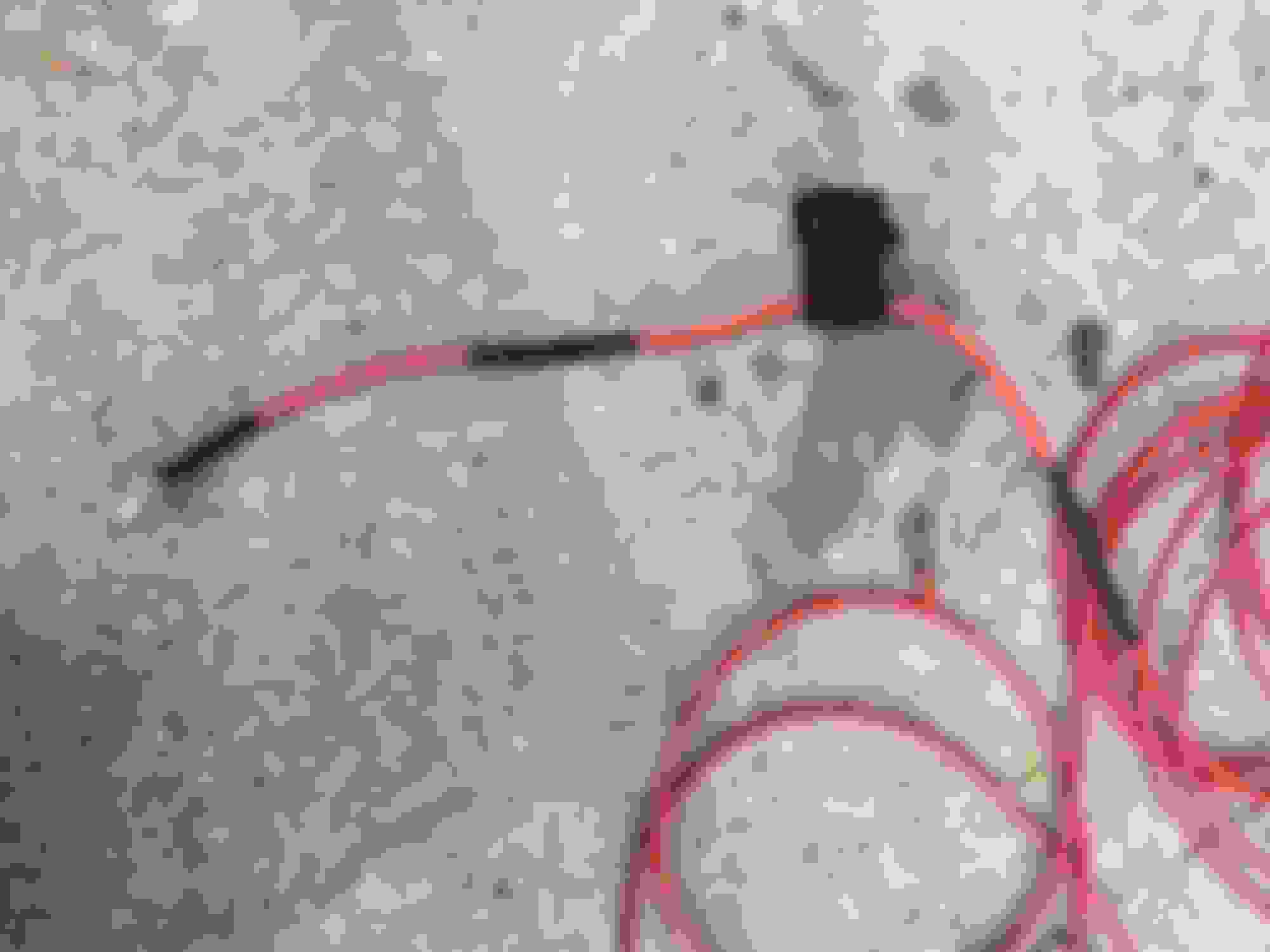
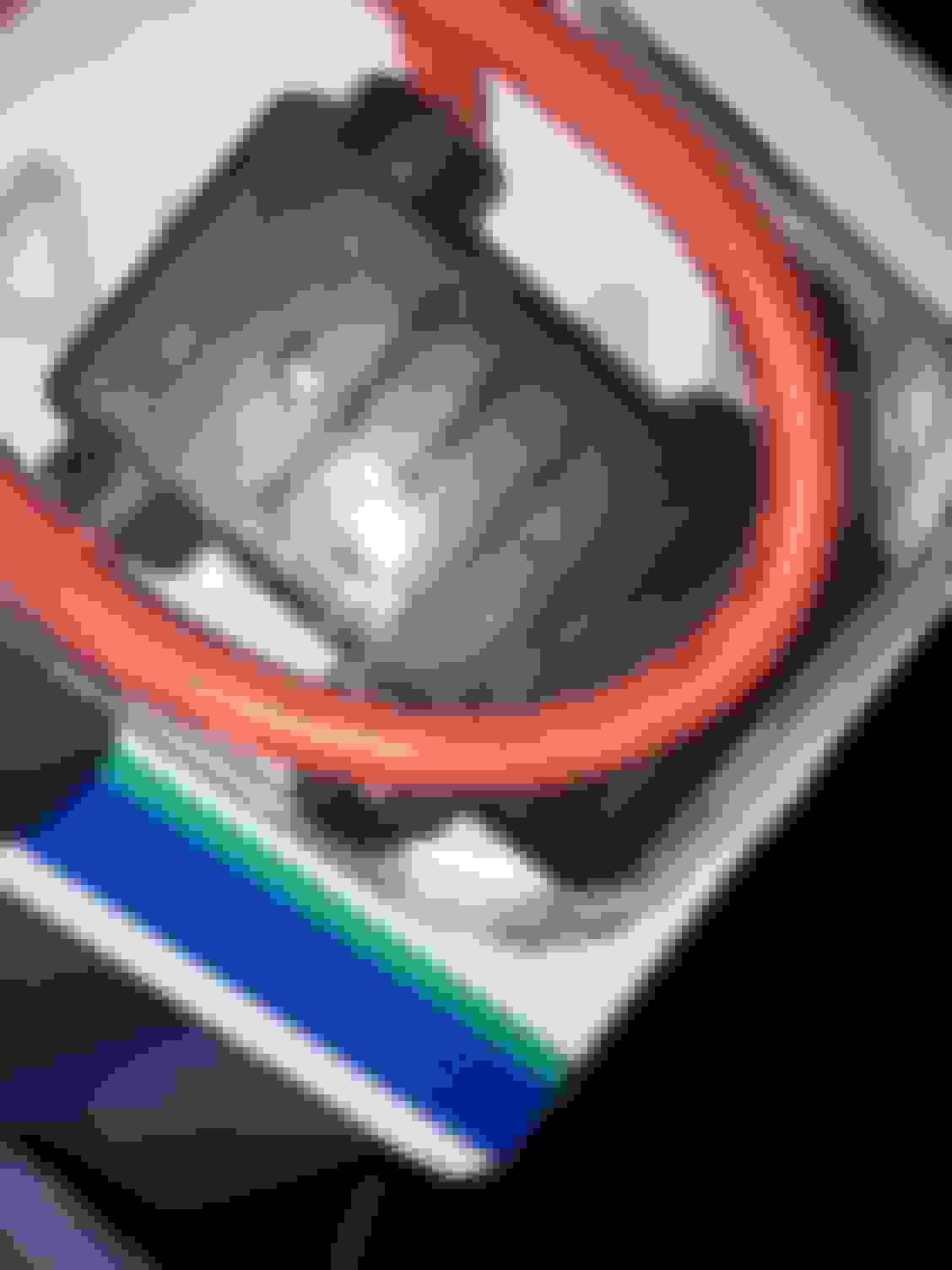
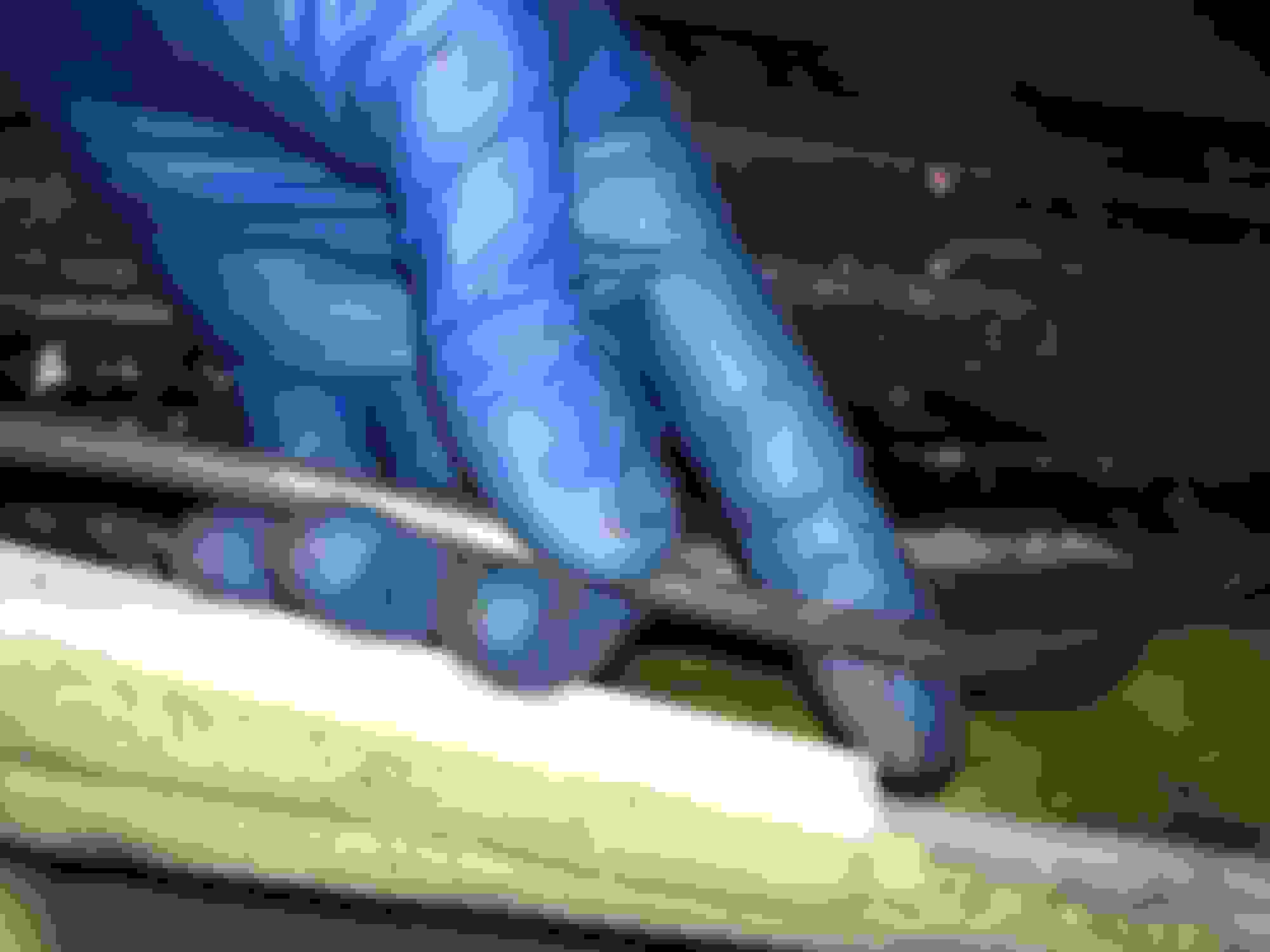
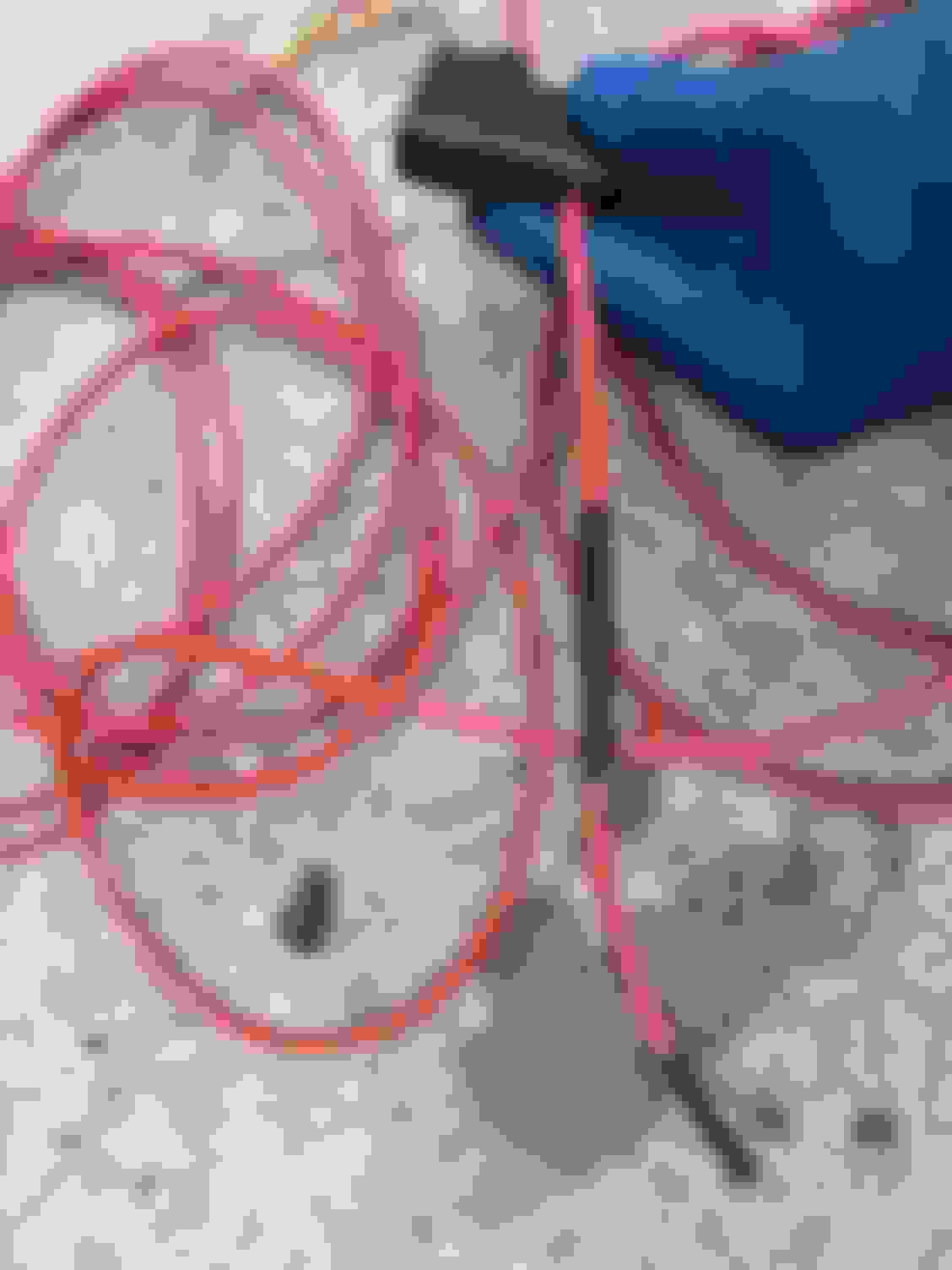
It wasn't cheap and took a few days to arrive but I ordered a GasTapper 12V kit. It's very slow, loud and requires some frequent adjustment of the siphon hose but it does work. I only bought it after I saw that someone had already tested it on a pre-98 SC400.
Note:Follow all the instructions included when using this kit and keep a close eye on the guide tube when messing with the angle of your filler tube. NEVER let the guide tube get so low in the SC's gas filler neck that you will have trouble gripping it to remove it later. It is a VERY easy to avoid any issue with this but just use common sense since the guide tube has nothing else attached to it up top to yank it back out with if it is shoved too low to retrieve. Trust me, with an SC300/400/Soarer filler neck the guide tube has enough length before this can occur to clear into the tank and allow the smaller siphon tube to feed in. I mention this because it might be tempting to shove it in even father than is necessary.
After using this kit it was still difficult to get down to any less than 1/4 tank but that got the level down low enough below the fuel pump access/seal plate to begin removing it without any fuel spilling out from the tank into the back seat area.
The easier way of course is just to drive your SC until the fuel gauge (assuming it and the tank sender are accurate and not in need of repair or replacement) reads 1/4 or less. I'd have preferred to do that but my old 2JZ-GE engine didn't agree with me.
Thank you very much, sir!! I've seen your extensive build thread before and I also could go on about your attention to detail and stealth approach! I saw you updated it just recently intending to take your SC back to daily status soon. Love your car! Are you still running the same STU GT28 USDM turbos?
Thanks! I am running the same turbos. Stu Hagen specials but they actually weren't GT28s. Just upgraded bearings and 12 bladed compressor.
This is one of the most common upgrades for not just SC's and MKIV NA's but numerous other tuner cars. It is pretty straightforward but there are a few specifics worth noting.
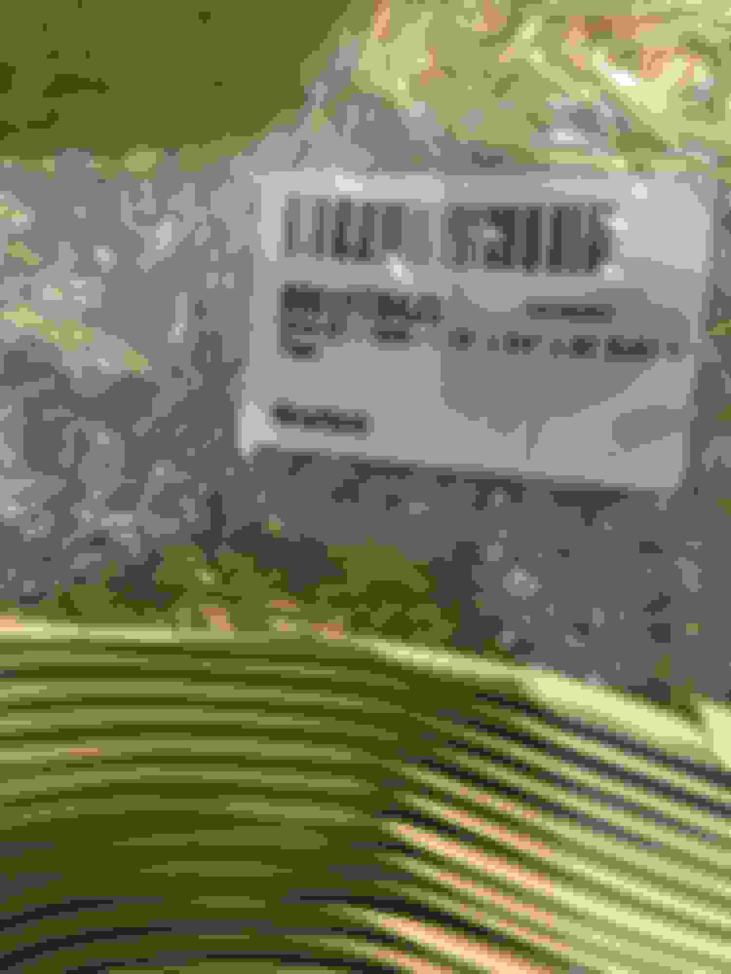
Before getting into it, here is an excellent exhaustive analysis and comparison which shows just why the Supra TT Denso fuel pump is so highly regarded and used in many aftermarket applications: http://www.stealth316.com/2-fuelpumpguide.htm
.....
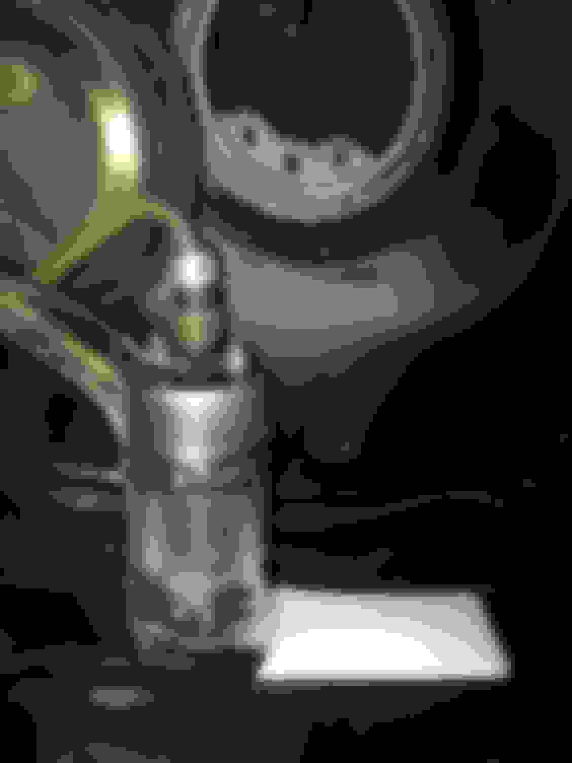
To begin, first, make sure your fuel tank is drained to 1/4 capacity. This is so that there is no chance of fuel pouring out onto you if the fuel level were higher.
Pry off the outer cover plate with a flat head screwdriver.
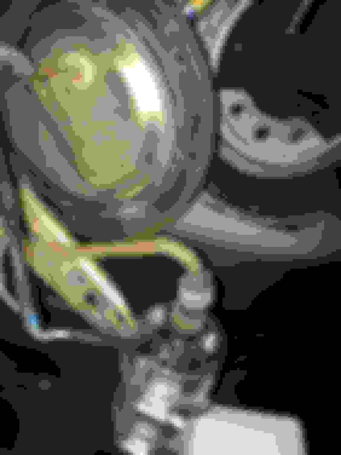
Have a new OEM replacement gasket ready to replace the old one that goes under the main sealing plate if it has never been replaced before. There are several screws in, I think, size M7, M8 or M9. Use a small magnetic tool when removing them to be 100% safe that they will not be dropped.
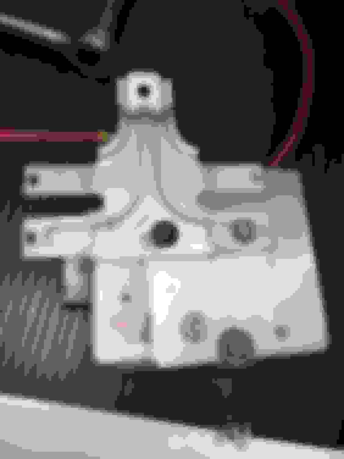
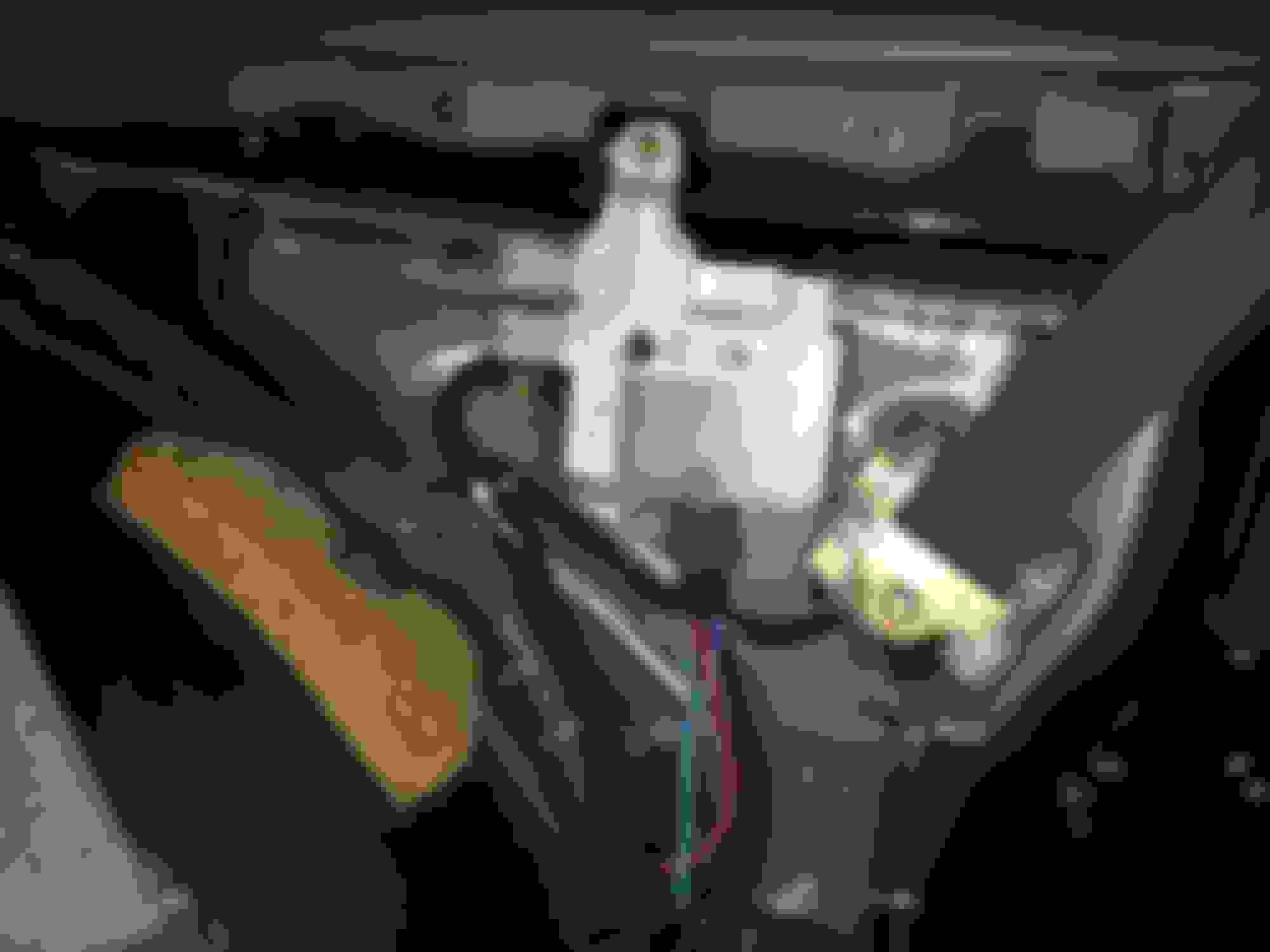
With the access plate now free, use an angled tension clamp pliers tool to pull the two OEM hose clamps downward but allow the lower one to rest freely on the metal pipe while the top one can clamp where that one used to be. This keeps the old hose tight on the hanger assembly while the top of the hose can be popped off. There may be some residual fuel under pressure that will come out for a brief moment. Have a rag handy to block anything from spraying.
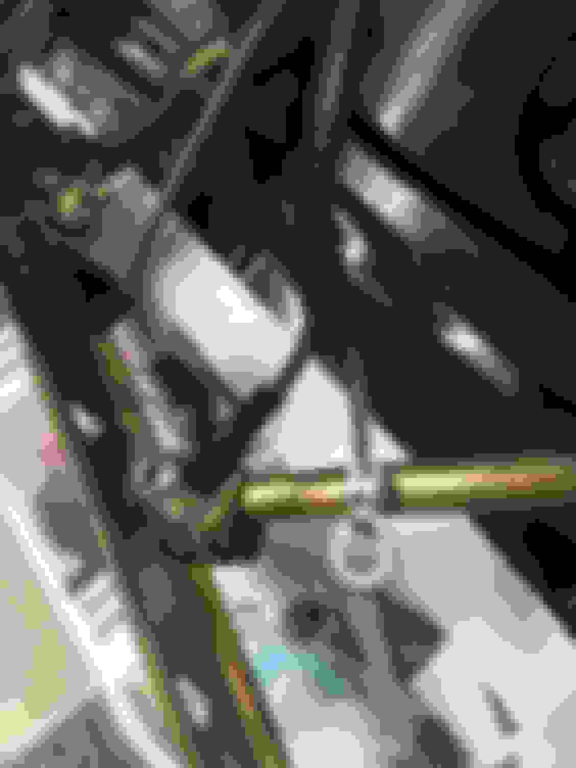
Three nuts hold on the hanger assembly. Undo them with (I think) a 10mm socket. Use that magnetic tool to be sure they don't accidentally drop anywhere (especially not inside the tank!!). Now you can remove the assembly. Be careful of putting too much stress on the wires that are connected to it.
Now put a thick rag into the access hole after you have removed the pump so as to block gasoline vapors. Wear a filtration mask if you are more comfortable that way.
Remove the SC300's NA fuel pump and place the Supra TT Denso (USDM/UK/Euro spec) pump into the same space. After affixing the supplied strainer with the tiny one-use securing nut on the bottom, re-use the specially shaped rubber isolator that came off the OEM NA pump. If you happen not to have it or if you lost this the part number is #23249-74610 (about $10 from most dealers). To secure the larger diameter pump to the hanger, use two stainless steel circle clamps. You may need to bend the hanger EVER so slightly to give just a few millimeters of distance between the metal pipe on the hanger and the plastic fuel outlet on the pump. Use the fuel hose and clamps supplied in the Denso TT fuel pump kit.
Before you tighten the clamps for good, note the orientation of the pump strainer/filter at the bottom. There is a slight angle to the SC's fuel pump hanger and you'll see that the strainer end will sit into what appears to be an internal baffle/bucket section inside the tank. Angle the strainer to be perfectly straight inside there. Test fit it to be sure before you finish this step.
Next, the connector that used to plug into the NA pump needs to be cut off at the very end. The two OEM wires are fine to supply the required 12V, 20A power to the TT Denso pump.
Strip just a bit at the end of each of them and note which is positive and which is negative. Get two ring terminals suitable for an M5 stud. Carefully remove any hard plastic or shrink tubing that is on it-- those will not work when submerged in gasoline. Common PVC tubing and most plastics will gradually disintegrate in the presence of gasoline.
Onto the two wires, slip on two small heat-shrink tubes of either Viton (preferred) or PTFE heat-shrink tubing that is advertised as being "fuel safe" or "fuel submersible". You can get either online or from a local Grainger Supply (Viton type which is what I used), or from a local West Marine (PTFE type).
Now remember the rag that is used to block the open hole in the gas tank to keep those vapors inside it? That is necessary for the next step.
Clamp the two wires onto the bare ring terminals and give each a little dab of solder to secure each wire in place. Only a small bit is needed. Now pull up those Viton or PTFE tubes and heat shrink them over the soldered area allowing just the rings to be exposed.
Secure the positive ring to the M4-sized stud (you'll see a "+" sign) and the Negative/Ground ring onto the slightly larger M5 stud. Use an appropriately sized plain crush washer and plain nut on each one.
Now you can reinstall the pump. Follow the TSRM torque specs for the three nuts that secure the hanger an for the many bolts that secure the main sealing plate onto the tank (torque loads are in INCH-LBS, so the appropriate torque wrench should be used-- usually $20 from Harbor Freight). Don't forget to use a new OEM gasket seal for that plate if yours has never been replaced before.
Now to replace the outer sealing plate, the SC300/400 TSRM specifies what is called "Butyl Tape". This can be bought inexpensively on Amazon or from common industrial suppliers. Get the thinnest width you can find and cut out one or two long strips to arrange where the old tape used to be (you have to pull that off beforehand). Then just align it and press it onto the hole.
Adding the 12V Battery (B) Wire and 30A Relay... and optionally the Supra MKIV TT Fuel ECU (if you want to have 9V-12V switching as per OEM for the MKIV TT)
Much thanks to Gerrb and Ali SC3 for their help and advice when planning this part! It's not hard once you know how but never having done this before I took a lot of extra time to be sure I knew what I was doing with wire gauges, connectors and especially the wiring of the relay (and Fuel ECU).
First I'll show how I got the 12V Mod w/Relay setup in place with the SC300 NA Fuel ECU. For most, this is how it is preferred since this will allow you to keep the safety of both the relay and OEM Fuel ECU (if you are using an OEM GTE ECU or other OEM ECU setup) but just using it to trigger the relay on and off directly to the fuel pump at 12V-13.8V.
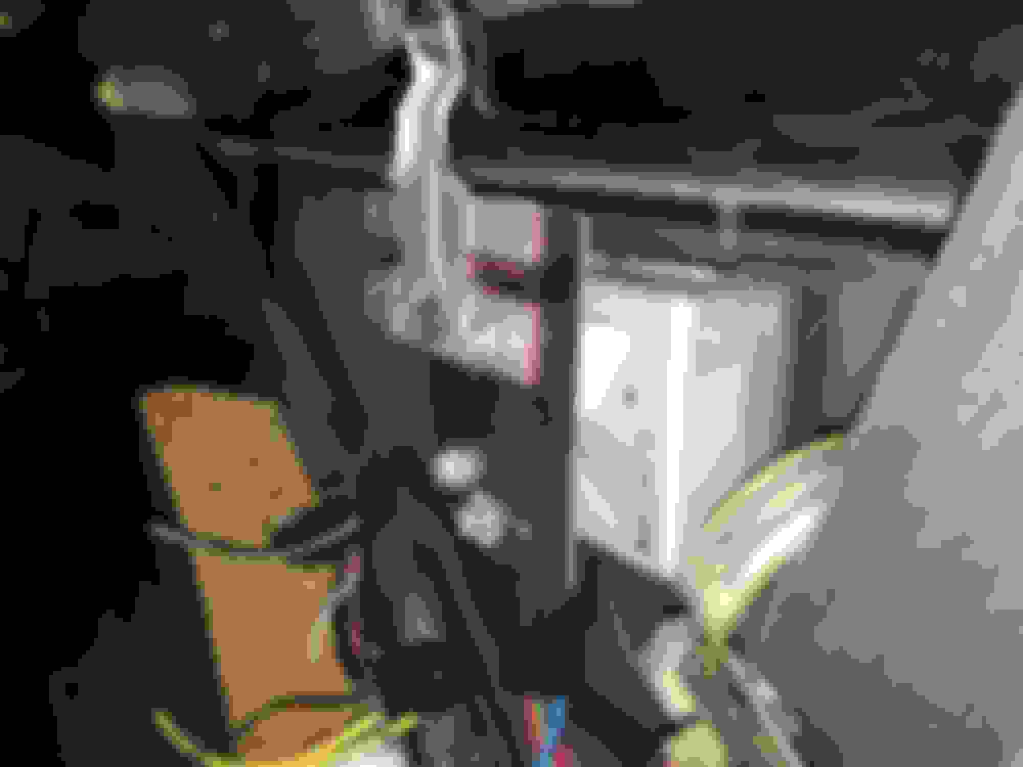
For just the one OEM Denso TT fuel pump I ran a length of red marine-grade stranged copper 10AWG wire from the positive battery terminal, through an in-line fuse with 10AWG wires, all the way through the access grommet at the back of the driver's side front wheel well... into the cabin, under the fuse kick panel, right alongside the other OEM wires under the carpet at the door's edge. I additionally got a long uncut length of heat shrink tubing and took some time getting it shrunk onto the wire. This gave 98% of it a black, OEM appearance in the engine bay and some additional protection. I zip-tied this wire to the factory wire bundle under the door sill and ran it up under where the OEM SC fuel ECU is located.
I used a Pico 30A two-pole relay which came with 14AWG wire. I have only found other models with 12 AWG wire online. It looks to be the same thing as a Bosch/Tycho model. I bought it as a little kit from a local engine builder's shop. I re-arranged the wires that came with it to suit the colors I wanted in the places I wanted them.
I de-pinned the wire in the 87 terminal and carefully pried the clamps of the spade terminal off the 14AWG wire. Then I inserted my 10AWG wire and clamped it down as best I could. I slid on two pieces of heat shrink tubing before I clamped the connector onto it. Then I soldered the wire on in an couple of places to secure it. Then I shrink on one heat-shrink tube and then the second one over that. Inserting the wire back into the relay harness connector was tight but it went in securely.
Now I made sure my relay terminal 30 had the 14WAG red wire to go to the fuel pump power. For the trigger (86) I chose a blue 14AWG wire. For the relay ground (85) I chose green and extended it a bit to a large ring terminal which was grounded to the body.
Here you can see how it should look in if you are going to use the SC300's NA Fuel ECU and just re-route its fuel pump output wire (green OEM from the NA Fuel ECU) to trigger the relay to to turn on and off for the constant 12V to the pump.
I mounted the relay on the side of the NA Fuel ECU using one of the small screws that holds the bracket onto its heat sink.
Here are a couple of good diagrams to show how this common setup is done (aka our 12V Mod but with a relay):
However... I opted to use the Supra MKIV TT Fuel ECU
As I'm keeping this swap very close to how a USDM Supra MKIV TT is set up and since I am not planning to go for high boost I wanted to retain the factory TT's 9V-12V fuel ECU control. If I ever want to or need to change this I can very easily bypass this function and still retain the safety of the 30A relay.
I know it isn't really necessary, apparently even for a USDM 2JZGTE stock swap with the intention of passing CA smog. The fuel pressure regulator will just work a little harder if the pump runs at a constant 12V pumping out maximum fuel pressure. It's common knowledge that the fuel system and TT Denso pump can handle it and be safe (with the 30A relay). My reasoning is that with this swap I won't be deviating much from stock in the first place so... since I had all the parts at this point I figured it would do no harm.
However, to reiterate, this is probably an overkill move on my part other than my wanting a 100% factory stock TT fuel system with the low and high speed pump control.
.....
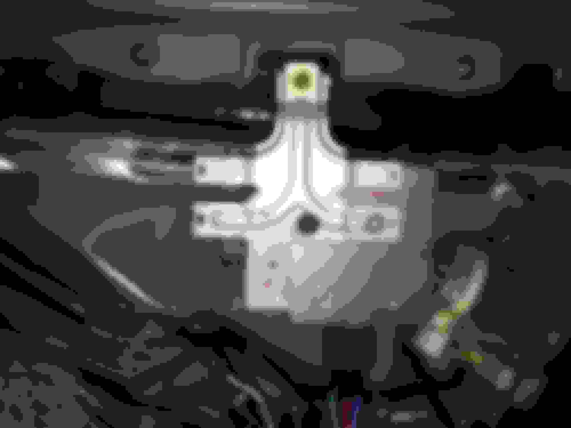
The first issue was fitment. The MKIV TT's Fuel ECU is substantially larger and thicker than the SC300's NA Fuel ECU. There is a reason it can handle the higher amperage. (Aside, I opened this unit up to inspect it and unlike the SC300's fuel ECU there is no glue goop inside to make it difficult to rebuild or re-cap if needed).
Eventually I only found one way to mount it and the easiest way I could figure out how to do it was to remove the mounting bracket from the SC300 Fuel ECU, bend the 90-degree mounts flat and cut and drill a piece of plate steel to affix it... and the MKIV TT Fuel ECU onto. I chose to mount the TT Fuel ECU sideways to have a better path to the harness wires.
...With the bracket finished:
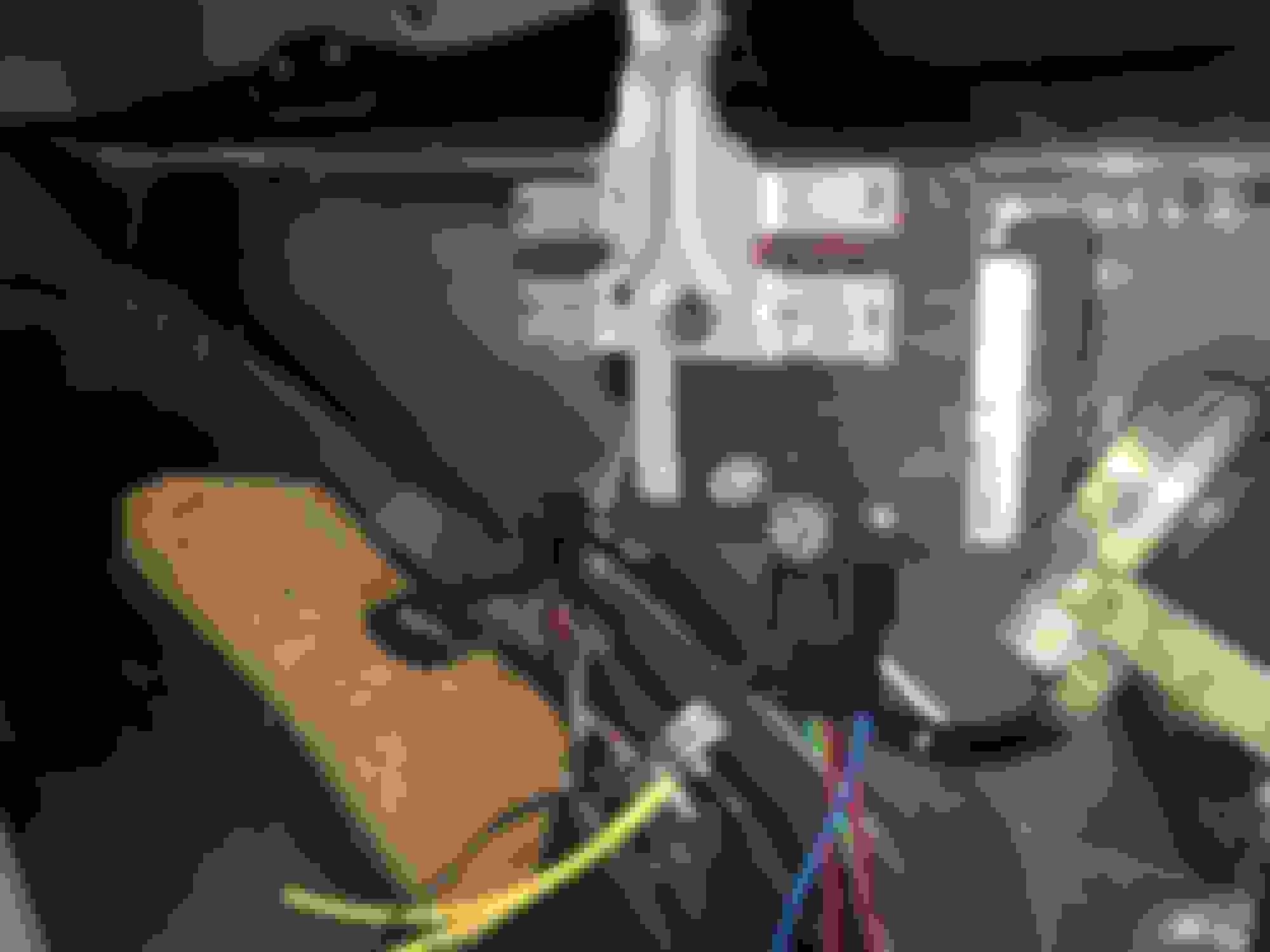
...And mounted in the SC. Plenty of clearance to put the interior panel back in:
Those wires needed to be extended however just to make it easier to route everything.
The basic control between the NA and TT Fuel ECUs from either the stock SC300 ECU and the MKIV GTE ECU is exactly the same.
Interesting that the three control wires do exactly the same things as explained below from Stu Hagen's 97supraturbo website: http://97supraturbo.com/mods/
"The stock FP ECU is controlled by the car’s main computer. Main purpose is to only run the fuel pumps when the engine is actually running. A Major safety thing. The other function of the ECU to FP ECU is running the FP at 9v up to 4000 rpms, then 12v above. This is done by the main ECU sending a 2v signal to the FP ECU telling it to pump out only 9v up to 4000 rpms. The the main ECU sends a 4v signal to the FP ECU to raise the voltage output to 12v above 4000 rpms."
Anyway... from there, it is necessary to put the correct wires in the correct locations. For the Supra MKIV TT's Fuel ECU I needed a spare 90980-11362 connector and some OEM repair wires to go with it. It turned out that I only needed two of the largest ones but I also stole a large spade white/black stripe wire that more closely matched the OEM SC's ground wire going into its connector.
TT Fuel ECU Connector (11362 / F15):
Pin 1 — 30A 12V Power (+B) (thick gauge)
Pin 2 — Power to fuel pump (FP) (thick gauge)
Pin 3 — NOT USED
Pin 4 — NOT USED
Pin 5 — IJ1-4 from Main Engine ECU (FPC)
Pin 6 — IJ1-12 from Engine ECU (DI)
Pin 7 — NOT USED
Pin 8 — (E) Fuel Pump ECU Ground and Fuel Pump Ground to Chassis Ground
SC300/400 Fuel ECU Connector (F16):
Pin 1 — Fuel ECU Ground and Fuel Pump Ground to Chassis Ground
Pin 2 — IJ1-8 from Engine ECU (DI)
Pin 3 — IJ1-14 from Engine ECU (FPC)
Pin 4 — 12V Power (+B) IJ1-12 on engine harness w/ thick gauge wire **NOTE**
Pin 5 — To Fuel Pump (FP) (thick gauge)
I soldered the 1362 TT Fuel ECU body side connector Pin 1 to my 30A relay's 14AWG terminal 30 wire and applied double heat shrink. The TT connector's Pin 2 was soldered to the 30A relay terminal 86.
The other three wires from my SC's body wiring on its fuel ECU connector were transposed as follows... and extended with more spare OEM wire in the same color and gauge from my junk SC300 Auto engine harness.
SC Fuel ECU Connector Pin 3 (FPC) --> MKIV TT Fuel ECU Connector Pin 5 (FPC)
SC Fuel ECU Connector Pin 2 (DI) --> MKIV TT Fuel ECU Connector Pin 6 (DI)
SC Fuel ECU Connector Pin 1 (Ground) --> MKIV TT Fuel ECU Connector Pin 8 (Ground) (*Note: spade is bigger on the TT connector. I found a suitable similar one from my spare junk SC300 Auto harness and used that to solder to the corresponding ground wire on the body wiring.
Here's a diagram of the wiring scheme that I used:
I took some more good OEM wire covering from that junk harness to give the extended wires some OEM protection. I also used some standard flex tubing to cover the 10AWG Battery B+ wire up to the relay.
And here's the final version with the wires tidied up. I added a bit more protective covering on the red and blue wires before I buttoned it all up.
Since the TT Fuel ECU has a substantially large heat sink on its rear I hope this will not get anywhere near hot enough to melt the factory plastic insulation sheet that it is only a few millimeters away from. Fingers crossed on that.
...
One more thing to note:
While researching how to do this part of the swap I became very curious as to why the Supra NA (just as with our SC300/400's) had a thick 14AWG or so +B power wire running though its harness and only one EFI Main relay... while the Supra TT had two EFI circuits.
I already understood how Toyota engineers wired the stock TT fuel pump power system up with the EFI2 relay on a totally separate B+ wire feed... but I wondered why they didn't just use an even thicker 12AWG or 10AWG wire through the harness just like the MKIV NA and SC300.
Then I located another Supraforums thread which held the answer (and I lost the link, sorry!). It comes down to not overloading the EFI Main circuitry, wires and relay with the duties of the 20A TT Denso pump ON TOP of already powering the rest of the ignition system from the coil packs to the ignitor, etc. It would just be too much amperage draw for that one circuit alone.
And so the electrical engineers for the MKIV TT decided on a second direct battery circuit with its own 30A relay triggered from the EFI1 (aka our EFI Main) relay. It's pretty much exactly the same thing as the 12V Mod w/Relay, just with a factory fuse box and relay location for MKIV Supras.
Granted, all of this with the TT Fuel ECU goes right out the window when setting up for big power, high boost and especially with an aftermarket engine ECU but at the end of the day it was interesting to learn how the system was originally designed to function and how to get it running properly
With everything wired up and finished I went about priming the engine with oil (and I squirted a little oil into the cylinders beforehand) with the ignition system disconnected, EFI Main fuse removed and spark plugs out. I put some shop towels over the open plug holes.
That went well!
Next, I reassembled everything and prepared for the big moment. Gerrb was very kind to let me call him that evening to walk me through it and get through the critical first 20min of piston ring seating (aka varying RPMs between 2000-3000 for 20min and then cooling down).
But it didn't happen. The SC would crank but would not start. Worse, there was a CEL light on.
Gerrb rightly directed me to check the first two cylinders (and spark plugs) for the smell of fuel but unless my sense of smell was no good on that evening I didn't detect any.
So at his suggestion this leaves using a spark plug tester (I'll get two so that the coil brackets don't have to be dismantled) and then testing for fuel pressure.
I could hear the fuel pump working and shutting on and off with the relay and Fuel ECU as it should... no problems there. My OEM TT fuel pressure regulator is used, however. Perhaps I should test that as well.
It was late and I was tired by that point and I packed things up for the night. Tomorrow I will try again.
However I did jump E1 and TE1 on the diagnostic port before closing up for the night to see what the CEL light was indicating. I counted the number of flashes many times to be sure I had each code written down correctly.
I would just disregard all of these if it weren't for my having a suspicion about all of them. I'll have to see if they resurface when I connect the battery again... and I WILL be doing tests on the ignition coil/plug spark on each cylinder and on the injector connectors to be sure that each of them are getting proper signal.
But my thoughts on those codes are:
#14 -- No IGF signal to ECM. It's possible that there is a bad wire in the system or that I may have mis-wired something. Hopefully not but what I do know is that I bought a used 1JZ/2JZ-GTE igniter without any confirmation as whether it was working or not. That is what is in the car now. I had planned to buy a new one later anyway so I bought a new 89621-22030 igniter from Driftmotion. I should have it by this afternoon. I could be WAY off here but I'm fine with having a spare new igniter on hand if I am wrong. I understand they rarely go bad, so the likelihood of this being my issue is low.
#27 -- Sub Heated Oxygen Sensor.
This refers to the 2nd TT O2 sensor that plugs in under the car. This is the one that I made a custom direct wire harness for because I couldn't figure out how to integrate the factory SC300 Cali-Spec under-car O2 sensor wiring (on the SC300 Cali-Spec OBD1 this is for the #3 O2 sensor with four wires... just like the MKIV TT's 2nd O2 sensor).
I did some research into the electrical diagrams and lo and behold I realized that I DID make a mistake. Thankfully this can be corrected under the glove box. I will do a further post on this fix alone but he gist is that I put the O2 sensor heater ground wire where the O2 sensor Heater Ground to ECU wire should have been. Here's hoping I did not damage anything but I will swap those two wires before starting the car again.
Further, I have now mapped where three of the four wires go into the SC IK1 and IK2 connectors. I'm just stuck on where the O2 sensor ECU B+ out to second O2 sensor wire plugs into. I suspect it is the SC IJ1-12 B+ wire... but I've got to look at the schematics again with a clear head to be sure.
For now, I will just correct my mistake on my custom direct wire harness and hopefully that will fix that CEL code. I can put those wires to the correct pins on the IK1 and IK2 body plugs later.
Note that this will only be possible on 92-95 SC300 Cali-Spec. Any Federal SC300 chassis has no pre-existing 3rd O2 sensor chassis wiring and the direct wire method must be used to connect the 2nd USDM Supra TT sub-heated O2 Sensor under the car.
#41 -- Refers to the TPS sensor. I'm not sure why this one is being thrown off but I'll have to see if the CEL code stays. Alternatively it could be for the TPS sensor for the TRAC system which I HAVE left disconnected... since I have no TRAC system at all. Not even a TRAC ECU Being a factory 5-speed there is no realistic way to have wired this in anyway.
Which brings me to...
#47 -- Sub-Throttle Position Sensor Signal. If this doesn't refer to the TPS sensor that directly influences the TRAC hardware (which I can't wire up and don't have) then I don't know what it is. But that sensor is definitely disconnected.
When it comes time to drive this SC back to California I must have all my CEL lights eliminated. But for now I can plug the removed TRAC motor and TRAC TPS sensor back into their respective connectors on the harness. If that eliminates the CEL 41 and 47 then I'll have my answer right there. Then I will have to figure out how to get the ECU to stop bothering me about them.
I can't have the antiquated TRAC system working in my car anyway even if I wanted to but it also has nothing at all to do with emissions control, so this is an elimination that is a no-brainer.
That's where I'm at now. The thread is up to date. I will put my notes for the 2nd O2 sensor wiring and the schematic references for the SC300 Cali-Spec and MKIV TT in my next post.
Here is hoping that my starting issue is as simple as just having installed a failed old igniter.
Thanks! I am running the same turbos. Stu Hagen specials but they actually weren't GT28s. Just upgraded bearings and 12 bladed compressor.
Ah yes! I'm familiar with that upgrade. The "standard GT28" compressor wheel and bearing upgrade/rebuild. This is likely what I will have done when I get one of my two sets of USDM twins rebuilt. Hope to see more of your car as you get it back on the road!
I corrected my mistake in wiring the 2nd oxygen sensor. I had the two ground wires reversed for Pin 1 and Pin 4. I was able to correct this very easily under the glove box right off my engine harness.
I replaced my old used igniter with a new one (P/N 89621-22030). Although it looks like it will fit, the new one I got doesn't bolt into the MKIV TT mounting bracket quite the same way as the old one. The connectors all fit and it's otherwise identical.
I also plugged in my TRAC TPS sensor and TRAC motor both on the USDM GTE throttle body.
After reconnecting the battery (it had been disconnected for a couple of days) and attempting to start the engine again... still no dice
The check engine light was on again and I put a paperclip in TE1 and E1 to see what codes were being thrown this time. A slight improvement from the last starting attempt two days ago: Code 14 (no IGF signal to ECM or bad wiring or bad igniter) was now gone. Code 27 (Sub-Heated Oxygen Sensor Signal) was also gone.
However I still had Supra TT CEL 41 and 47 coming up. Even though I think those just relate to the TRAC system, since I plugged both the TRAC motor and TRAC TPS sensor into their respective connectors this time and those CELs still come up I will at least look into these some more to see if they are influencing anything.
Nice to know that I got rid of the other two CEL codes. That's something.
I didn't have any extra help today to run spark plug and coil testers so that will have to wait until tomorrow. At Gerry's suggestion I will try to get the car jacked up and remove the fuel feed line from the filter-with-mushroom thing on the side of the engine block, point it into a bucket or low pan and watch to see if fuel is coming out when the car is started.
I again pulled the spark plug from cylinder #1 and smelled for fuel. All I smelled was residual anti-seize paste from its threads that I applied the other day.
Other than that, I'm going to start reading the full MKIV TT TSRM rundown on how to diagnose and test the SFI (fuel) system and the ignition system.
I don't suspect my USDM 2JZ-GTE OBD1 6-speed M/T ECU because I had it inspected and re-capped by Driftmotion back in 2016.
Whatever is keeping the car from starting must be very simple. I just have to find out what it is.
Update to Thread Post #521: Wiring and Pinouts for the MKIV TT Sub-Heated (under car) Oxygen Sensor & partial SC300 Cali Emissions 3rd O2 Sensor Wiring Path Pinout:
If you go back to this link to Post #521 on Page 35 of this thread I have updated that post with corrected wiring pinouts for the under-car sub-heated oxygen sensor for both the SC300 OBD1 California Emissions models and the Supra MKIV TT. I have also added the TSRM pages for both vehicles showing the wiring paths for this in each.
The only thing missing that I have not yet figured out is where the 3rd Oxygen Sensor's Pin 2 in the SC300 Cali-Emission model goes to in the IK1 or IK2 body plugs. It wasn't yet clear to me at this time. Read the post and you will see. Hope this will help anyone who needs this sensor hooked up.
I have included a 75% complete cross-reference pinout for these wire terminals on the sub-heated under-car O2 sensor between the 92-95 SC300 Cali-Emission chassis and 93-95 Supra MKIV TT chassis. That table is missing where the pin 2 goes on the SC300.
A Fix (I think?) for my USDM MKIV TT CEL Code 47 (TRAC Sub-TPS sensor error code)
Unrelated to my current starting issue...
This, I think, is the answer I've been looking for to defeat the CEL Code 47 I've got. Since my SC300 never came with a TRAC system of its own and since the TT TRAC system isn't that good (or safe in the opinion of many) in the first place, there is no good reason for it in this build.
It took plenty of hunting but I found this writeup on clubna-t.com which seems to pin down exactly what needs to be done to make it go away:
Originally Posted by captdale
I just finished a couple more tricks I thought I would share.
Check engine light on due to a code 47. When you do the NA to TT wiring mod there is no longer a TRAC. Because there is not a TRAC the ECU flags a code 47 which is a sub-throttle position sensor fail. The Sub-throttle position sensor info is used by the TRAC system. To get rid of the check engine light associated with the code 47, just place a jumper between ECU B41(5vdc, VCC) and B42(sub throttle pos sensor,VTA2). That provides a +5 VDC signal to the ECU VTA2 telling it that the Throttle is WOT. Makes the ECU happy and the code 47 goes away.
So if that does work for me, that would eliminate the Code 47 (Sub-TPS).
The CEL Code 41 for (I think?) the main TPS sensor seems to be unrelated then...
Here's another take on the same fix, this time listing the use of 220kOhm and 15kOhm resistors instead of a plain jumpers. I'm not sure which is the best to use but resistors sound... safer?
Originally Posted by Andi
I'm assuming you already disconnected the TRAC TPS.. (if you hadn't've, you'd have a real bad stumble/hesitation off idle..)
For reference, prior to finding that thread I came across a few on SupraForums which go into a different method for eliminating the TRAC delete CEL light issue by means of some resistors... but I get the impression that they are referring to a different set of plugs than the ones that go onto the TRAC section of the throttle body on either side.
Here is that quote:
Originally Posted by Autobox
if ur lookin at the pic above yall see there are 4 wires goin to the sub-tps...
E2 is the ground and you dont need to worry about it
now yall need two resistors....a 10k ohm 1/2 watt and a 1m ohm 1/2 watt.
now take the 10k ohm resistor and put it into #1 and #3....
next put the 1m ohm 1/2 watt into #1 and #2....
basically sj told me that when u test the sub-tps when it is opened, you should see 2-10.8k ohm between #1 and #3...(the 10k ohm resistor creates this). Then when u test between #1 and #2 you should see over 1m ohm (1m ohm resistor here). in essence the ecu thinks the sensor is there...and is open....
ill try to post pics....but its basiclaly like every other resistor mod on the supra....ur foolin the ecu by giving it what it wants.....some range of ohms that the sensor SHOULD be sending it.
And not that 90% of this applies here but there are a couple of pictures of the TRAC throttle body plugs in this writeup (thankfully spared from the PhotoBucket debacle):
And the description below of how the 2JZGTE ECU might act unless this pesky TRAC TPS sensor and Code 47 were to be dealt with doesn't sit well with me. Although thinking about how this system works for a moment, perhaps it would be much more likely that the TRAC motor left in the other side of the throttle body (mine is removed) is the only thing that could cause the poor off-throttle response by closing that plate?
Originally Posted by Jade Supra
I just figured out last night that if you don't disconnect the trac position sensor, the ecu reads that it is closed. This caused the horrible off idle response. Disconnecting it, for me at least, caused a check engine light...
Edit/Addition: Here are two diagrams from the 1995 MKIV TT Wiring TSRM and MKIV TT 2JZGTE Troubleshooting TSRM to illustrate where these pins are located.
If the TRAC system wires/connectors were left as-is when converting the 2JZ-GTE swap harness it seems like it would be the easiest and least invasive solution to add the resistor at the connector near the throttle body as suggested by one of the quotes above, between Pin 3 (VTA) and Pin 4 (VC) of the Sub-Throttle Position Sensor connector.
Last edited by KahnBB6; 07-27-18 at 02:25 AM.
Reason: Added notes for sub-throttle TPS connector pins
Craig - remove the hose (after stock fuel regulator) that goes to the hard return line to confirm if you have fuel supply. IF there is and nothing on your cylinders / plug then your injectors are not firing . That can be a variety of reasons... ecu , wiring , crank / cam sensors , etc . The spark would be a lot easier to test .
Gerry, thank you! I will be trying that soon. You mean the section of fuel supply hose that bolts to the engine fuel feed near the starter, correct?
Almost everything on my engine in terms of electronics are new or reconditioned:
Main ECU -- inspected and re-capped by Driftmotion
Crank sensor -- brand new OEM
Cam sensors -- brand new OEM
6x USDM 550cc fuel injectors -- bought used but sent to Driftmotion for sonic cleaning, re-balancing and flow testing. Those were all confirmed to be in good shape.
Every kind of sensor and VSV on the engine are all brand new OEM with the exception of the used discontinued TT EGR VSV and USDM 550cc resistor pack... and the used and converted engine harness wiring.
I'll have to rule out the fuel getting to the engine first but I am thinking it is more likely a fuel issue rather than a spark issue after looking at one of my brand new plugs before reinstalling it.
I think I should also try the "FP and +B" fuel ecu bypass to engage direct 12V to confirm whether that TT Fuel ECU is working properly. I have another spare and I could also swap that one in if there is a fault in the one currently installed.
Craig - remove the hose (after stock fuel regulator) that goes to the hard return line to confirm if you have fuel supply. IF there is and nothing on your cylinders / plug then your injectors are not firing . That can be a variety of reasons... ecu , wiring , crank / cam sensors , etc . The spark would be a lot easier to test .
Wait a minute... I think I misunderstood earlier... you don't mean the line below the engine that goes up TO the fuel rail. Do you mean the beginning of fuel return hose? That does come from a metal line after the FPR and then to a rubber hose and then to the main fuel return hard line.
So I could just connect another length of fuel hose to that FPR line and do it that way, correct? And as a plus, I don't even need to jack up the car for that
 07-12-18, 08:29 PM


 Being a factory 5-speed there is no realistic way to have wired this in anyway.