When you click on links to various merchants on this site and make a purchase, this can result in this site earning a commission. Affiliate programs and affiliations include, but are not limited to, the eBay Partner Network.
--The CARB approved K&N cone air filter kit came in. I haven't done a test fit yet.
--The Driftmotion remanufactured PS pump came in. I bolted it onto the GTE engine but it is slightly loose in the bracket. I looked up the factory parts diagram for it and no additional washers were specified. I may need to add two thin ones just to make it sit snugly like my original PS pump did in its original bracket. Or maybe I should remove the brand new OEM PS pump bracket and install the old one that I took off my GE engine.
--Installed the TT ignitor, USDM TT resistor pack and got my original SC theft horn to fit on the shock tower and clear the TT PS reservoir with a little creative bending of the theft horn mounting bracket.
--Did some investigating of my Cali-Emission SC300's #2 O2 sensor body plug wiring. Observed that it goes into a larger harness that leads up into the dashboard. While I'd love to re-use this factory O2 sensor wiring and get it to the appropriate wires on my GTE harness... that's just too much work to get into. Will continue with creating my own custom interconnection harness from that factory location on the side of the transmission tunnel all the way to the engine ECU and body plug area for a direct connection (to be detailed in a future post soon).
--Fuel return and fuel pressure lines disconnected and tied up.
--R154 clutch slave cylinder removed and tried up and out of the way.
--Removed the rest of the 2JZ-GE intake and fuel system to have more room in the engine bay for now
Now I'm down to needing to remove the driveshaft before I can unbolt the crossmember and block mounts and pull out the engine and transmission. I *MUST* do this first, correct? I've looked up the TSRM procedure for removing the driveshaft and have printed those pages for reference.
Due to having a less than 1" drop from the garage floor to the driveway pavement directly in front of the SC I think I will have to put the pass side front wheel back on, lower the car onto its own weight again and roll it out onto totally flat pavement before attempting to use a 2-ton hydraulic engine crane and load leveler to pull out some 700-ish pounds of 2JZ and R154 transmission. Unfortunately there just isn't much more room to work with in there, the SC being stuffed into there as it is.
It's looking like it might rain all this week so I may need to hold off even longer before doing the big day-long job.
The Driftmotion remanufactured PS pump came in. I bolted it onto the GTE engine but it is slightly loose in the bracket. I looked up the factory parts diagram for it and no additional washers were specified. I may need to add two thin ones just to make it sit snugly like my original PS pump did in its original bracket. Or maybe I should remove the brand new OEM PS pump bracket and install the old one that I took off my GE engine.
Great progress bro...keep up the good work!
Keep a close eye on that reman'd power steering pump. From what i have seen, the bearings and gaskets the re-manufacturers' use are not as good as the OEM Toyota "Koyo" parts. Seals and bearings start leaking prematurely. That was one of the reasons I rebuilt mine using OEM parts....just worth noting.
Keep a close eye on that reman'd power steering pump. From what i have seen, the bearings and gaskets the re-manufacturers' use are not as good as the OEM Toyota "Koyo" parts. Seals and bearings start leaking prematurely. That was one of the reasons I rebuilt mine using OEM parts....just worth noting.
Thanks man! Well my original PS pump was leaking and leaving residue all over the hoses and various things below it so I needed to replace it or rebuild it.
I do have the OEM Toyota/Koyo PS pump rebuild kit but decided to give Driftmotion�s remanufactured unit a try since the price was right and it�s them and not some random company. If problems arise later on then I will pull it and rebuild with the factory kit.
The looseness in the bracket is annoying and I don�t know what to attribute that to but I will get thin stainless washers to shim the difference. I�ll also try that pump inside my old bracket just to confirm that isn�t the issue.
The objective here is to create a direct connect harness that will go from the factory #3 O2 sensor connector location on the SC300 (remember, all Cali-Spec SC300's and 96+ Federal SC300's have this connection under the car which goes through the interior side of the transmission tunnel) to the body connector area of the passenger footwell.
Note that with my Cali-Spec SC300 there is an existing wiring path for this sensor to get its signal to the ECU... but it gets buried in the dash harness wiring.
It's possible that I could trace where these wires go to (presumably to the same location this custom harness will be going) but it's a lot of trouble and I don't know the pins that it is supposed to terminate at. Further, the USDM 2JZ-GTE harness seems not to have a standard way to connect to these pins as is.
If the answer is that the SC body plug body-side connectors have the four connection points then it would be nice to identify them for the future, but what I have read suggests that the GTE harness needs this direct connection to the sensor.
Some reference photos of the starting location...
Where the SC300 Cali-Spec 2nd O2 wiring disappears into...
And the overall view of the short path for this direct wire harness.
It's been very rainy here in Florida lately and unfortunately that means I haven't been able to get much time on a dry and sunny day to move the car out of the garage and perform the actual engine swap yet. I may buy a large canopy tent at this rate.
In the meantime I've focused on knocking out a few more things:
--Installed the USDM TT injector resistor pack (glad I had a used bracket for these because like the resistor pack they are discontinued!). An alternative to these if anyone needs to know is an injector resistor pack for a 1991-1995 Acura Legend. The same connector is used and it plugs right in. The only downside is that it's an old Acura part with a different shape vs an old Toyota part with the original shape.
--Installed the USDM GTE ignitor. Luckily I had a bracket for that too. Interestingly in addition to all the other factory 1JZ-GTE and 2JZ-GTE JDM vehicles the 1994-1999 Avalon also uses this same ignitor unit.
--Removed the 2nd SC300 cat pipe to get to the driveshaft and realized I've run out of garage space at this point. The D/S removal and draining of the R154 has to be done on wider, level ground. The big outdoor canopy tent is sounding like a better idea the more I think about it.
--With the Driftmotion remanufactured power steering pump installed in the new OEM PS pump bracket I noticed there was some wobble even with the bolts being tight. I took a feeler gauge and tried to determine if I would need some super thin washers but the gaps I was measuring were so very small that I'm sure no one sells such thin washers. I then tried my old PS pump bracket and lo and behold the pump fit snugly as it should. Now I could have just installed the grimy old bracket and honestly I'm now aware I didn't need to buy another one but since it was still in there I just used a hammer to lightly tap in the two front dowels *slightly*. This did the trick and the new PS pump fit correctly with no wiggle room.
--Next, I set on my GE engine's PS pump pulley but found it had wobble when I tightened it down. I checked the input shaft of the new PS pump but it was true so I took a fine metal pick and cleaned any debris or shards of metal I could find on the splines. With the pulley in place again I still observed a *slight* wobble but it was not what I had seen initially before cleaning the splines. It's there but minimal. If this will be a problem I guess I'll need a new PS pump pulley but that I will leave for later if problems arise.
--More mockup and measuring of the #2 O2 sensor direct wire extension harness. I need some good plastic insulation that doesn't heat shrink to slide the wires into-- looking for this. I think I'll hold off on soldering the other end of it until the GTE harness connectors are inside the footwell. I don't want to make it too long... or too short. Also, I had to order another 90980-11028 connector after all as the locking pin for one of my wires on the old one I was re-using had broken. A replacement is currently on order.
--Just because I happened to be going through my parts box and came across the OEM seat heater switches I'm looking into enabling this circuitry and the factory relay and fuse so that I can add seat heaters to my MKIV seats later on. I already have the connectors for the SC seats that go into the floor connectors so I figured... why not? There is some further documentation and existing thread info on this side project that I will put up later... or perhaps in its own thread. I narrowed down the likely connectors for the seat heater button assembly (on the bezel/switch side) for SC300 factory 5-speed harnesses down to two: 90980-10932 or 90980-10934... so I ordered both to see which it is. The body-side harness connector is 90980-10933. We'll see if one of these turns out to be correct.
The seat heater switches are exactly the same for all 1992-2000 models but the end connectors are different for M/T and A/T cars (the A/T versions with seater heaters and TRAC also include pins for the TRAC ON/OFF button which is bundled in with the seat heater buttons). De-pinning an A/T version (which is what I have) and replacing the end connector with the correct M/T connector should be easy... so long as I've identified the right one in the parts system.
--The MKIV TT PS pump remote reservoir requires two hoses. One is a 16mm ID hose with the OEM Toyota P/N 44348-14120 (aka 44348-24040) and the other is a 10mm ID fuel hose that Toyota will not sell you without the entire PS cooler assembly for an MKIV TT. An old post on SupraForums has Curt Aigner himself simply suggesting to take your old 10mm ID hose to any auto parts store and get a replacement. So that's what I did. I took my GE PS hose in that diameter to an Advance Auto and got plenty of 9.52mm ID fuel type hose. I cut it to a reasonable fit and used screw clamps (one of the few times I've done this on the build) and that's now solved.
--I was able to remove both the MKIV TT and SC300 cruise control cables from their respective cruise units with the help of some PB Blast spray and Vise Grip pliers directly onto the phillips screw (which did scar the outer edges of the screw heads). These were installed by Toyota with Loctite Red. No wonder I stripped one of these screws trying to get them out! I repaired a disintegrated protective covering on part of the (discontinued) MKIV TT cruise control cable and installed it onto the Lexus SC300 cruise control unit. Perfect! I may add a little thin rubber or foam protector to make it clip into the cruise cable holder/guide a little better.
......
And with the cruise control unit now figured out that brings me to another fun conundrum in the form of the #57-9004 K&N CARB Legal intake: it doesn't actually fit a USDM TT MAF.
At first I wondered if I had ordered the wrong part but after checking the CARB EO database and vigman's USDM 2JZGTE swap thread it is indeed the correct one for "87-95 Supra 3.0L - Turbo" which has the important and correct CARB E.O. D-269-40 number. I'm thankful for the thing being certified but I'm perplexed by the inclusion of an adapter plate with the cone filter that looks like it fits a 2JZ-GE's Karmann-Vortex sensor rather than a round Supra TT's MAF.
After a Google search I read this thread which confirmed my concerns:
So with that I've ordered an "MA70-FA LIPP Air Filter Adapter" in the Natural Aluminum finish (which I assume I'll need to at least apply a clearcoat seal to) from SupraSport and that should do the trick so that I can still use a CARB legal intake that clears my SC300 cruise control unit.
For once a very simple solution to a potentially big issue has presented itself!
I'd just use my MKIV TT stock airbox if only the SC cruise control unit's stock location didn't make it impossible to fit. And I do want to keep my cruise control function.
Both USDM MKIV TT's and JDM JZZ30 Soarers use two different locations for their factory cruise control units (the MKIV TT's is packed against the ABS unit's metal pipes and the JZZ30 Soarer's, being RHD, is if I recall correctly, on the other side of the car since the brake boosters are reversed in RHD's).
....
Let's see, what other progress has been happening...
....
--Bell Intercoolers is currently re-coring my early JZZ30 side mount intercooler and setting it up for the late model JZZ30 factory IC shroud. That should be ready by the end of this week.
--After Toyota Fest the great folks at Organized Garage Status will be repairing leak issues in a spare LH tail light assembly for me which has been badly needed as my original and my spare LH tail light assemblies both allow in water and moisture which harms the bulbs and electrical harness.
--AutoExtrude has sent me one of their 3D printed ashtray dual gauge pods with the DC port option. Can't wait to see that in place.
--EGauges is sending out my VDO voltmeter and oil pressure gauges to populate that assembly. Unfortunately I learned that VDO/Continental in Germany has a massive backorder on the 1-DIN US-spec TR7412UB-OR radio I've bought. It seems they designed it a year or so ago thinking there would be just a small demand from the aftermarket for them but they've proven to be VERY popular especially among owners of older Porsches, Mercedes, BMW's and VW's. And me Who'd have guessed car enthusiasts actually want a simple, OEM quality and retro 90's simplistic car stereo that uses old fashioned buttons and has modern features like Bluetooth audio and handsfree phone, a built-in microphone, aux input, a function for cars with old style retractable antennas and all in a front face that doesn't look like a deranged flashing disco ball on your dashboard? Looks like I could be waiting on my new head unit possibly into July or August
Since pictures/video do help, here is a review of the 1-DIN head unit I'm waiting for. It's very basic but clean and well made:
I threw the passenger side wheel back on and lowered the SC off the jack stands. As soon as I have a clear day the fun will really start.
One thing is for certain: I really, really miss driving this car. I can't wait to get it on the road again soon. Everything is coming together simultaneously and few roadblocks are ahead now.
Last edited by KahnBB6; 05-22-18 at 11:49 PM.
Reason: Minor grammatical corrections
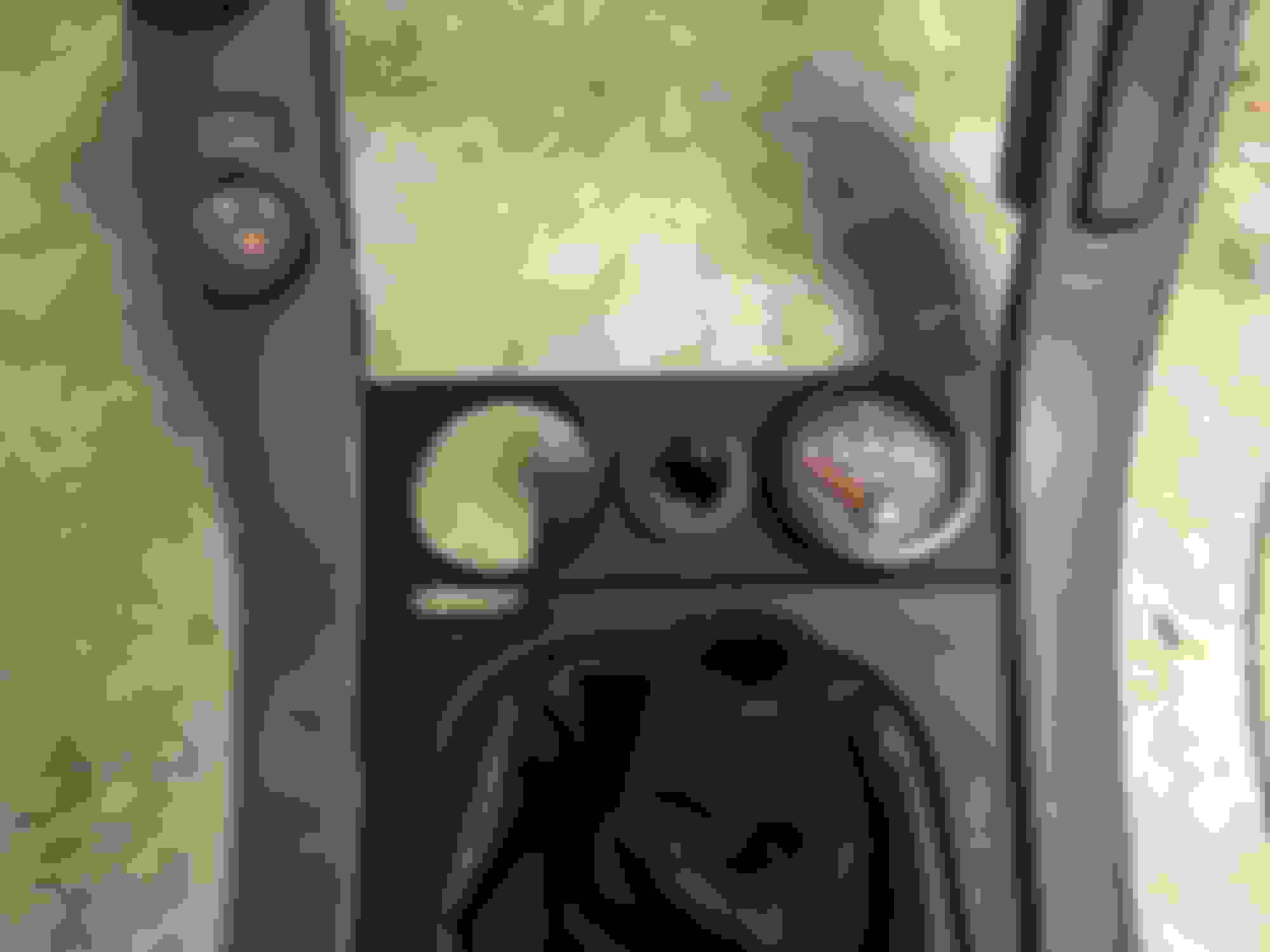
The AutoExtrude twin 52mm gauge panel that replaces the ashtray came in.
Doing some test fitting in the console surround today. I opted for the “hammered” finish. It’s clean and I love it! Only a very tiny bit of Dremel trimming was needed in the back to fit the right side VDO Vision Black gauge’s lock cylinder.
The gauge pictured probably won't stay for now as I haven't (yet) had my R154's main housing tapped for a 1/8" NPT threaded pressure sender. For anyone who is curious, VDO requires a 10-180 Ohm 12V sender for this trans pressure gauge.
Similarly styled 0-16V voltmeter and 0-150 PSI oil pressure gauges will populate these. I may change to another center DC port as the one that comes with this one doesn't accept some of my DC plug accessories.
...I was able to figure out how to set up the needed ground wire at SC IK2, Pin 24 to get my factory cluster temp gauge working with the GTE engine. While the gauge temp sender's wire goes to SC IK1, Pin 9 the SC's are set up from the factory to ground this gauge circuit from within the harness... while Toyota Soarers and MKIV Supra TT's ground this wire from on the chassis side connector for IK2-24.
Prior to discovering this old thread I was going to solder in a 330 Ohm resistor in line with the IK1-9 temp sender wire.
I made a post in there to add some detail from the SC300/400 TSRM schematic for the dash temp gauge sensor and also to offer my take on how to do this-- just ground IK2-24 from the harness side body plug rather than the chassis side.
I have many spare wires and terminal ends from a spare SC harness so I just found a terminal end that fit the SC IK2 connector and some length of brown SC harness wire to solder onto the terminal end.
Now I have what I need to ground that connection. I just need to decide if I want to run it into my harness to an existing ground bundle or if I will just ground it somewhere in the footwell area or possibly at an existing ground area on the tunnel floor below the stereo area.
I wish I had known about this while working on the first pass of the GTE harness conversion. At the time I could have easily run this wire to a suitable ground location well before taping everything up.
On post #89 , after the first pictrure I posted where I encircled that pin IK2-24 , I have explained where that should be grounded . It is part of the harness .
On post #89 , after the first pictrure I posted where I encircled that pin IK2-24 , I have explained where that should be grounded . It is part of the harness .
Aw nuts
Thank you for pointing this out Gerry! I definitely missed that note when I was doing the initial wiring on my pinout checklist :/ In your post it says that the ground end point is on the front of the GTE intake manifold. I don't suppose there is any ground wire connection in the harness behind the firewall connector that will let me junction into that ground connection?
Such as the SC IJ1-18 SRS and O2 sensor ground wire which are right in the body connector area? But that probably won't work or will just add uncharted noise to the those two circuits, right?
Or can I just as easily run that ground wire into the trans tunnel floor behind the radio head unit so as to avoid unwrapping the harness again?
In all of my wiring notes this really is the last one that has been unaccounted for. I guess I will need to tear apart the taping again and run it through to the manifold ground wire. I'm so close but... live and learn...
....
However before I do this fix for the IK2-24 ground I'm concerned I'll need to account for more wires being added if I want to get the correct signals for the MKIV TT aux electric fan harness built and working... which uses two separate relays and both the A/C Mag Clutch wire as a trigger for the aux fan during A/C operation and the TT radiator temp sensor as another trigger that comes on when the coolant temperature gets to 213F and goes off once the coolant temperature is down to 196F.
It seems that I can build that factory TT aux fan relay harness mostly outside of the engine harness other than the one wire for the A/C Mag Clutch signal.
If I tear into the harness again I want it to be the very last time I do it.
Maybe I should also run two wires for the oil pressure sensor I'll be using with the VDO gauge in the console panel... but I figured I would run that in a separate wire bundle through the firewall access point near the clutch master cylinder and close to the steering shaft. I already have my aftermarket fog light harness switch wires ground through there.
^^^ you can tap that wire to any of the wires of pin 69 or 79 or 80 of the 80 pin ECU connector and resolves your problem. The IK2-24 then is like being grounded to the engine.
Thanks Gerry!! That saved me a LOT of trouble. I used pin 69 and a little extra length of brown wire in the same gauge from the spare SC harness with a bare butt connector crimped and soldered at both ends and heat shrink tubed twice over. Re-taped the harness. Nice and clean again.
Now I've only got three main electrical projects left to do:
1) Finish the 2nd O2 sensor direct harness that takes the sensor connector from the side of the trans tunnel to the the engine harness.
2) Complete the +12V Fuel Mod w/relay... or figure out how to wire in one of my two USDM TT Fuel ECUs (which I have a harness side connector and terminal ends for)
3) Figure out the wiring for the aux electric fan to use the two relays, the radiator sensor/switch and the signal from the A/C Mag Clutch wire. Both in Florida and in California I know that's going to be needed.
But with the last wire connection on the harness now having been sorted for good, it's time to install the engine
After much preparation it's finally underway! It's been pouring rain but that hasn't stopped me
Also, as a friendly public service message: never use an impact gun on your transmission's drain and fill plugs. I know this. You know this. Your friends know this. Your friends' friends know this. Everyone who's ever been in the same fast food order line for a burger and fries behind your friend's friends knows this. But the last mechanic (not me) who changed the transmission fluid on my R154 must have missed that one. Maybe I have a bad angle under the car but my drain plug is on so tight I feel I might round the hex bolt trying to take it off.
As such, I'm not going to drain the R154 before removing the driveshaft and crossmember. You're supposed to first but I feel that I'll have a better time loosening that overtightened drain bolt with the transmission out of the car.
I hope to have the GTE and R154 with the new Southbend clutch installed tomorrow or Monday.
I was inspired by chnk's post detailing his OEM TT electric fan setup and control wiring (https://www.clublexus.com/forums/bui...ml#post9194714) and so I ordered a Mishimoto electric fan harness (Mishimoto P/N MMFAN-CNTL-U18NPT) to complete the wiring for the TT OEM auxiliary fan. Since I opted for the verson that has a 1/8" NPT temperature sensor I'm replacing the MKIV TT factory coolant temperature switch that goes into the bottom of the radiator. To make the Mishimoto sensor fit in the factory sensor location in the radiator I've ordered an Earl's 16mm-1.5 male to 1/8" NPT female aluminum adapter (Earl's/Holley P/N 9919AUJERL).
I studied the factory electrical schematic for the MKIV TT auxiliary fan control system. Just for the single 1993-1996 fan setup I was a bit thrown by the complexity of the complete circuit I'd have to build with two relays, the radiator temperature switch and A/C mag clutch trigger. The Mishimoto kit requires that I figure out on my own how to manually adjust a screw to the factory 212F coolant trigger point that Toyota engineers intended but it uses a less complex wiring scheme than I would have had to replicate from the Toyota schematic. And it has an A/C override wire built in.
It's rated for 25 amps max current draw no matter the number of fans used. The MKIV TT's factory fan relay system was designed for a 30 amp fused circuit. What I'm hoping (and chancing) is that the single 93-96 heavy duty cycle OEM TT electric fan doesn't draw any more amps than that. If chnk managed to hook up the 97-98 MKIV TT twin OEM auxiliary fans with this same harness without issue then I should be fine with just one.
For the K&N filter kit I've ordered a 3" silicon coupler and HPS clamps to bridge between the USDM TT MAF and the SupraSport MA70 Lipp air filter adapter. I ordered my adapter in plain unpainted aluminum but I'm painting it with 220 degree rated black satin VHT alloy wheel spray paint and a final single pass of VHT 220 degree clear. I did need to obtain some longer than provided (with the K&N kit) 6mm-1.0 stainless hex head screws, some washers and some stainless hex nuts with the plastic filling inside.
I'll detail that process and the Mishimoto fan control wiring install when I have all the parts in and once this chassis has a new heart in its engine bay.
...
It's a weird feeling to finally be at this stage after at least five years now since this project started
Thank you very much, Anders! How have things been going with your cars? A while back you bought another MKIV TT, didn’t you?
Well, yesterday I learned how to pull an engine and transmission out
I have plenty to do with the R154 tomorrow: cleanup, fluid draining (despite the tail plug, some spilled so it has to be done), new output shaft seal, new drain+fill plugs (hex type), new SB clutch kit and bolting onto the GTE.
Now something that concerns me is if my hydraulic engine crane might not have enough capacity to lift and lower in the 650lb 2JZ-GTE with the 135lb R154 bolted to it at the extension length I needed. It's a got a 2-ton rating but just to get enough distance into the engine bay to pull out the 2JZ-GE with the R154 I had to extend out to the bolt hole marked "1/4 ton".
Now I know the stripped down 2JZ-GE (as you see it pictured below) must have weighed maybe in the 350lb range at most so I was probably fine at the 500lb crane arm rating at that extension length. I'm not so sure this crane will be strong enough to load in 785lbs of engine and transmission at that same extension length.
Perhaps I need to buy or rent a bigger and longer crane for the re-installation? Or... maybe I should consider installing the GTE engine by itself and figure out how to get the R154 installed after the fact?
Though I've used engine cranes before this has been my first time removing an engine with a transmission attached and it will be my first time installing an engine and transmission combination with a crane.
Some (slightly fuzzy, sorry) pictures from yesterday:
Now I know that my original Lexus engine mounts were totally shot. They both broke in two very easily when the engine lifted out.
I installed the SupraSport MA70 Lipp air filter adapter onto the K&N #57-9004 cone filter plate after painting. I regret that I used a single top coat of VHT matte clear on top of the prior VHT satin black but it’s ok.
I bought some slightly longer allen head stainess screws (6mm-1.0) and some stainless nuts and washers.
I tried making my own gasket from a sheet of Fel-Pro material but it didn’t work out well and didn’t seem necessary once I thought about it. The metered air doesn’t start until after the TT MAF anyway.
A 3" black silicon coupler and two HPS clamps will arrive tomorrow so there will be no holdup on getting that installed.
Now something that concerns me is if my hydraulic engine crane might not have enough capacity to lift and lower in the 650lb 2JZ-GTE with the 135lb R154 bolted to it at the extension length I needed. It's a got a 2-ton rating but just to get enough distance into the engine bay to pull out the 2JZ-GE with the R154 I had to extend out to the bolt hole marked "1/4 ton".
Now I know the stripped down 2JZ-GE (as you see it pictured below) must have weighed maybe in the 350lb range at most so I was probably fine at the 500lb crane arm rating at that extension length. I'm not so sure this crane will be strong enough to load in 785lbs of engine and transmission at that same extension length.
Perhaps I need to buy or rent a bigger and longer crane for the re-installation? Or... maybe I should consider installing the GTE engine by itself and figure out how to get the R154 installed after the fact?
Though I've used engine cranes before this has been my first time removing an engine with a transmission attached and it will be my first time installing an engine and transmission combination with a crane.
take out your front bumper , aluminum bumper crossbar support and light support to be able to push the hoist all the way inside the bay... you will have a lot of room and that hoist is more than enough if you have a 2 ton rating hoist... engine and trans are less than 1/2 a ton.
 05-12-18, 11:37 PM


 Who'd have guessed car enthusiasts actually want a simple, OEM quality and retro 90's simplistic car stereo that uses old fashioned buttons and has modern features like Bluetooth audio and handsfree phone, a built-in microphone, aux input, a function for cars with old style retractable antennas and all in a front face that doesn't look like a deranged flashing disco ball on your dashboard? Looks like I could be waiting on my new head unit possibly into July or August


 . Almost there. I�m happy for you!