When you click on links to various merchants on this site and make a purchase, this can result in this site earning a commission. Affiliate programs and affiliations include, but are not limited to, the eBay Partner Network.
^^ Following up on last month's post I finally installed the front sway bar today. I had to find the time to schedule a hydraulic lift stall rental. Very easy and straightforward installation. I discovered one of my end link boots was torn while installing the Supra TT front bar. I'll have to order a set of those in the near future but for now I hope the old end links last a while longer. I used new TT front swaybar bushings to baseline that part of the front suspension.
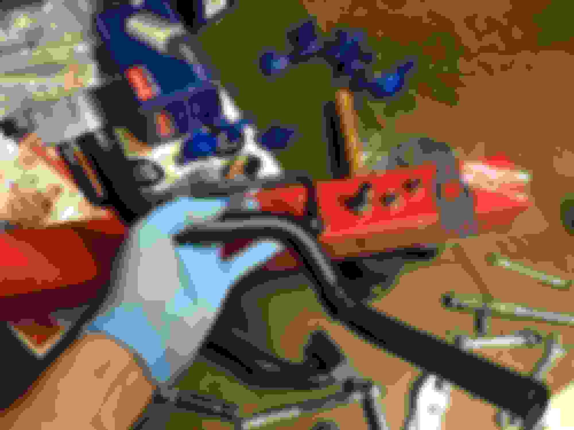
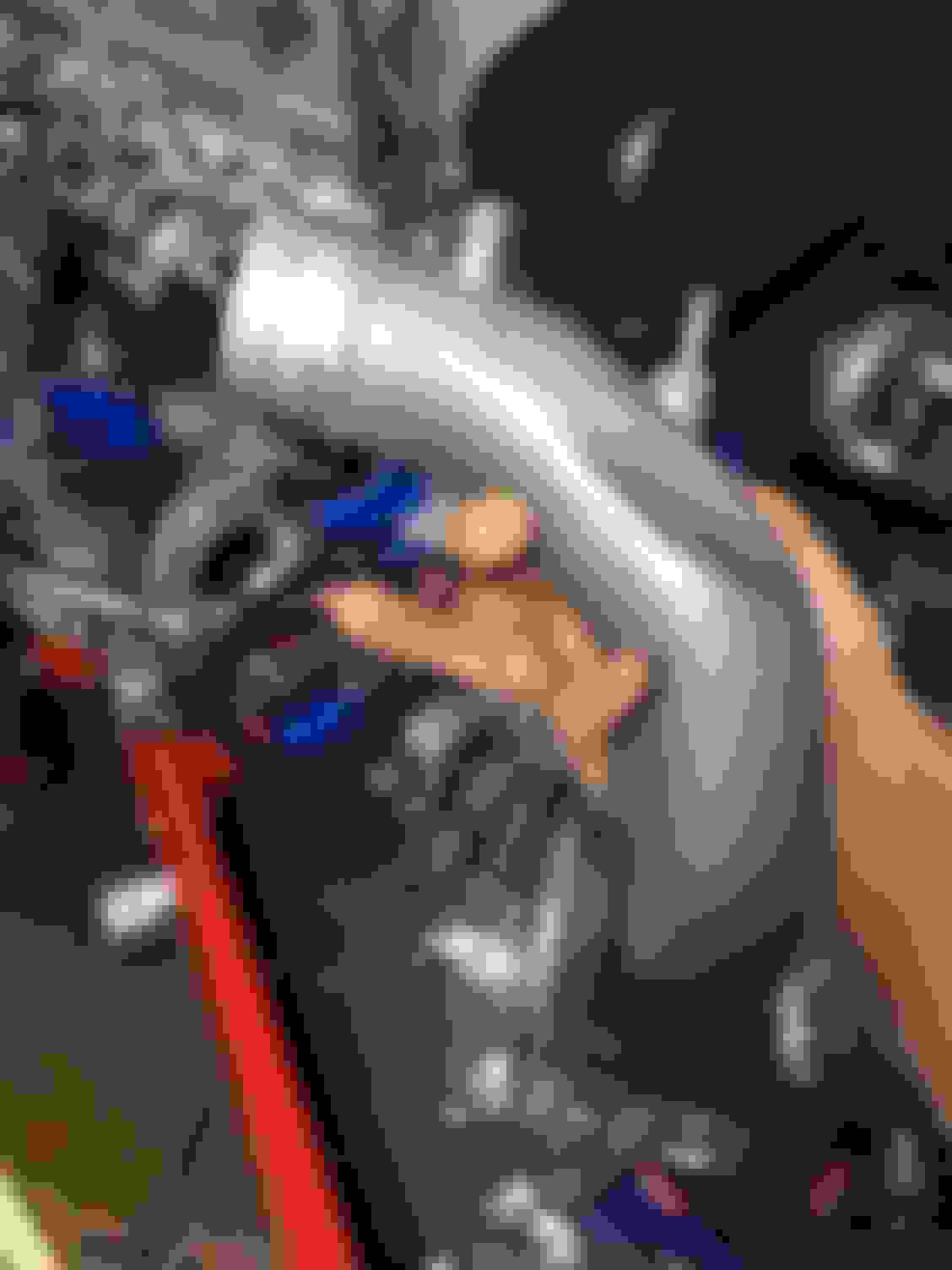
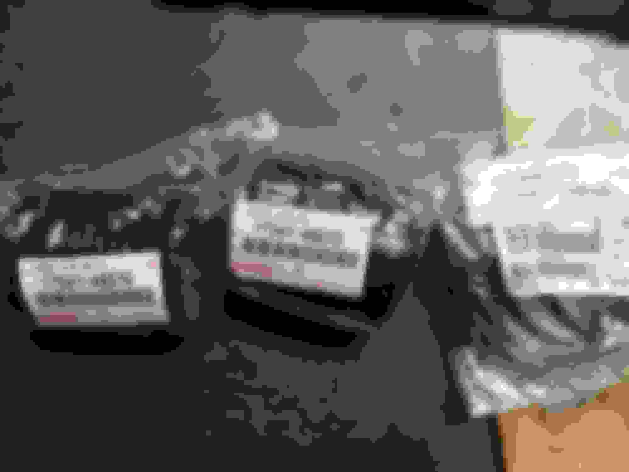
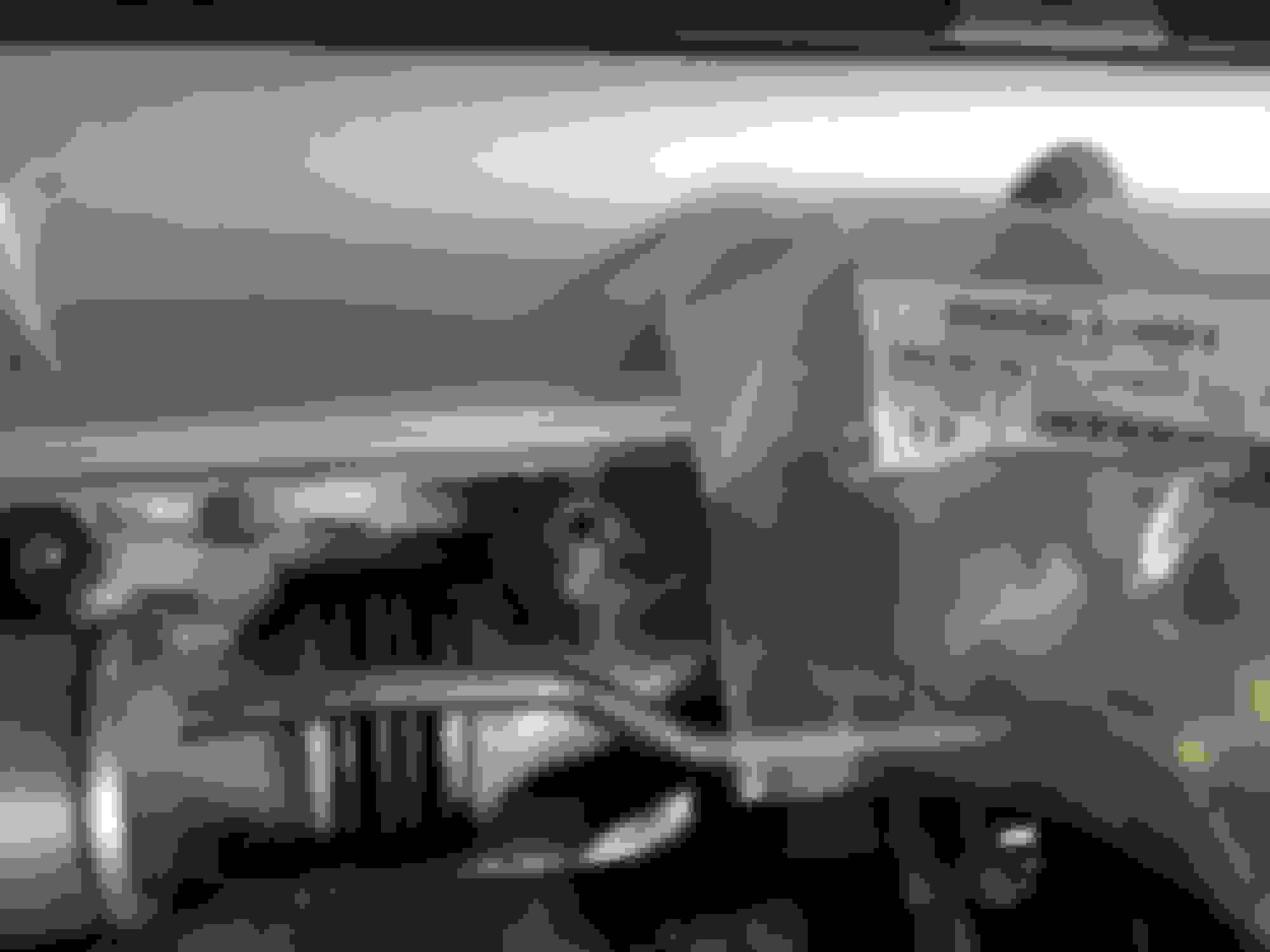
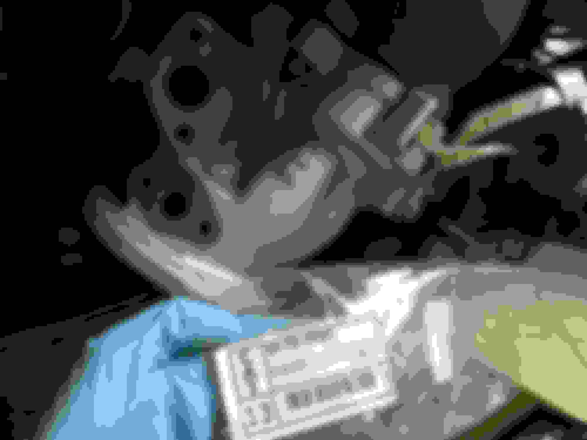
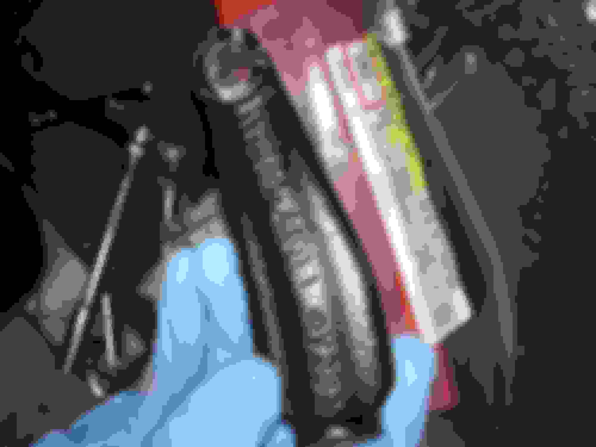
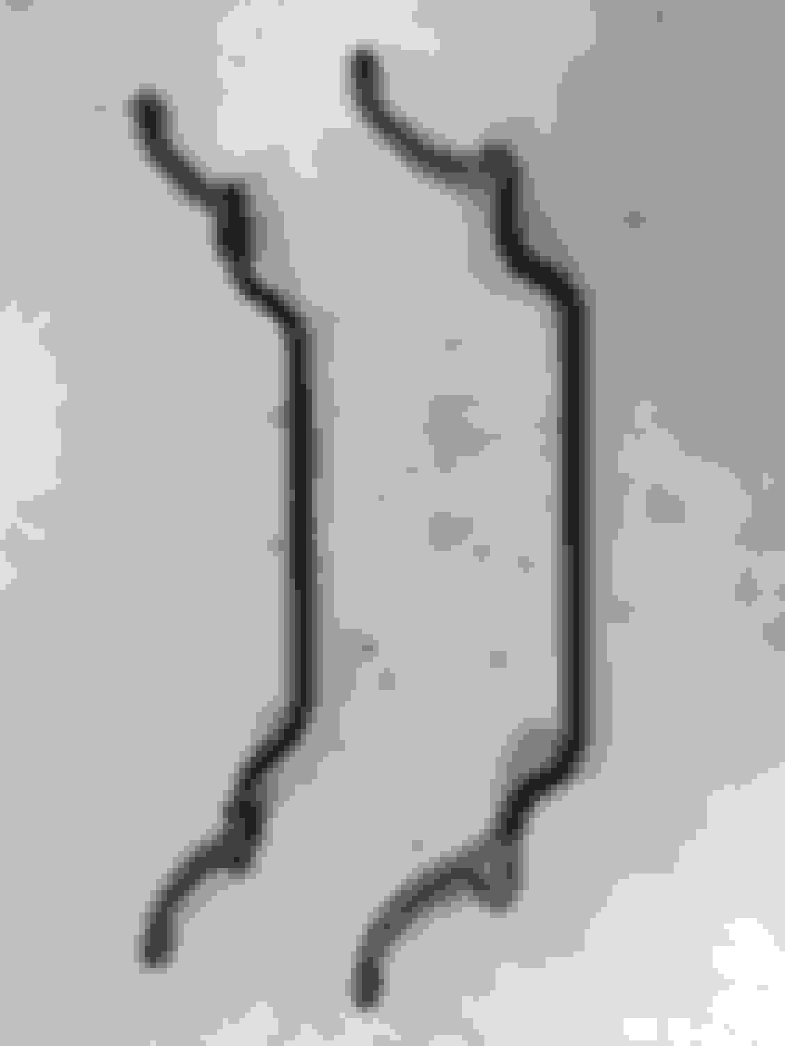
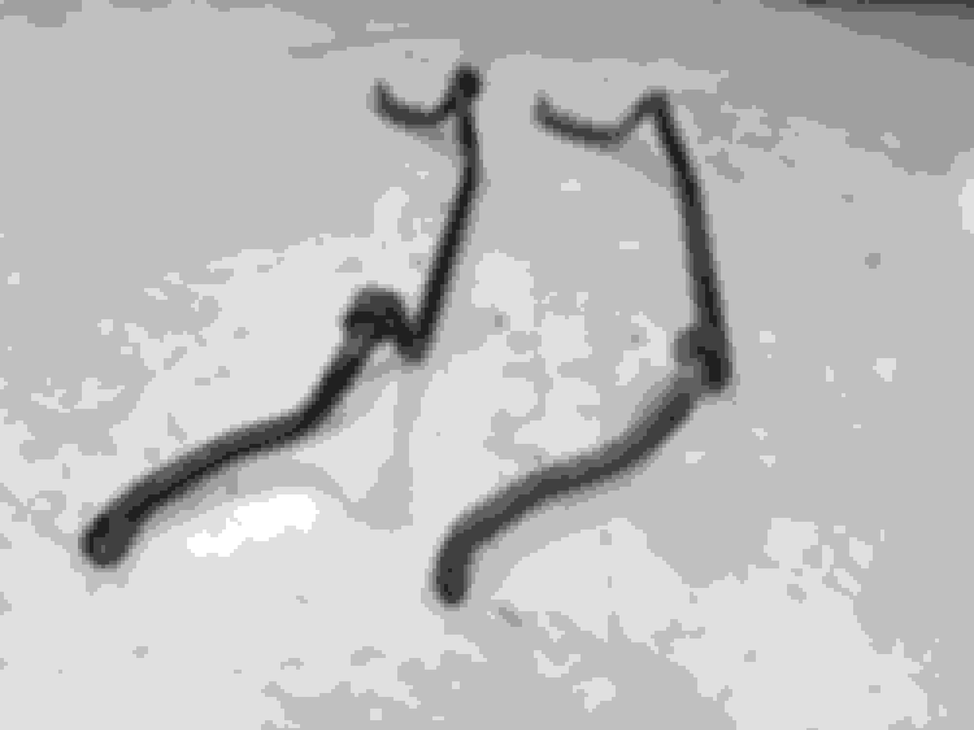
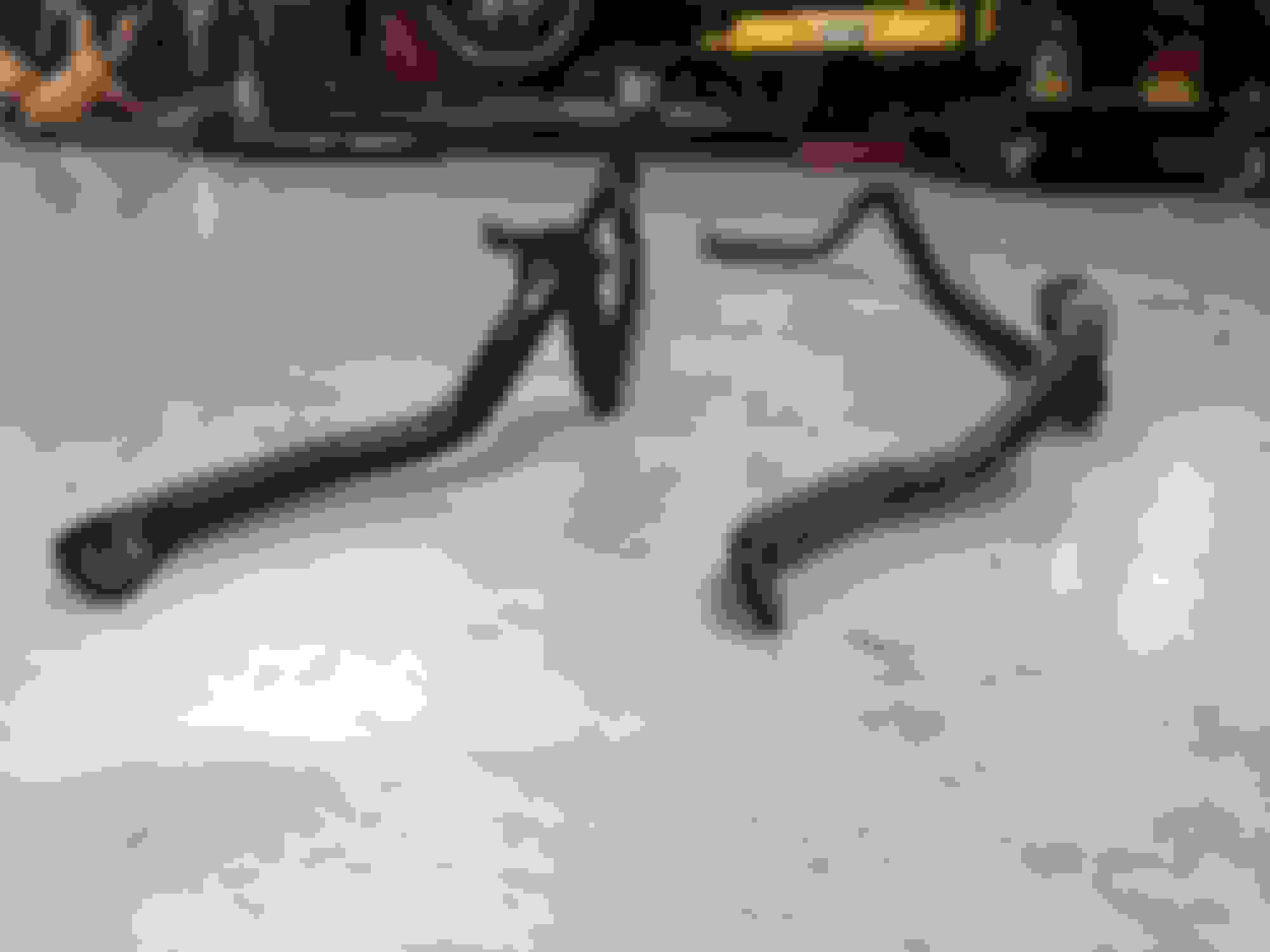
A comparison of the SC300 and Supra MKIV TT front sway bars. Note that they look very similar to each other but there is a slight difference in the bends of each. The TT swaybar also weighs a bit more than the SC300 sway bar.
On the left... the 1993.5-1998 Supra MKIV TT front sway bar.
On the right... the 1993 SC300 front sway bar.
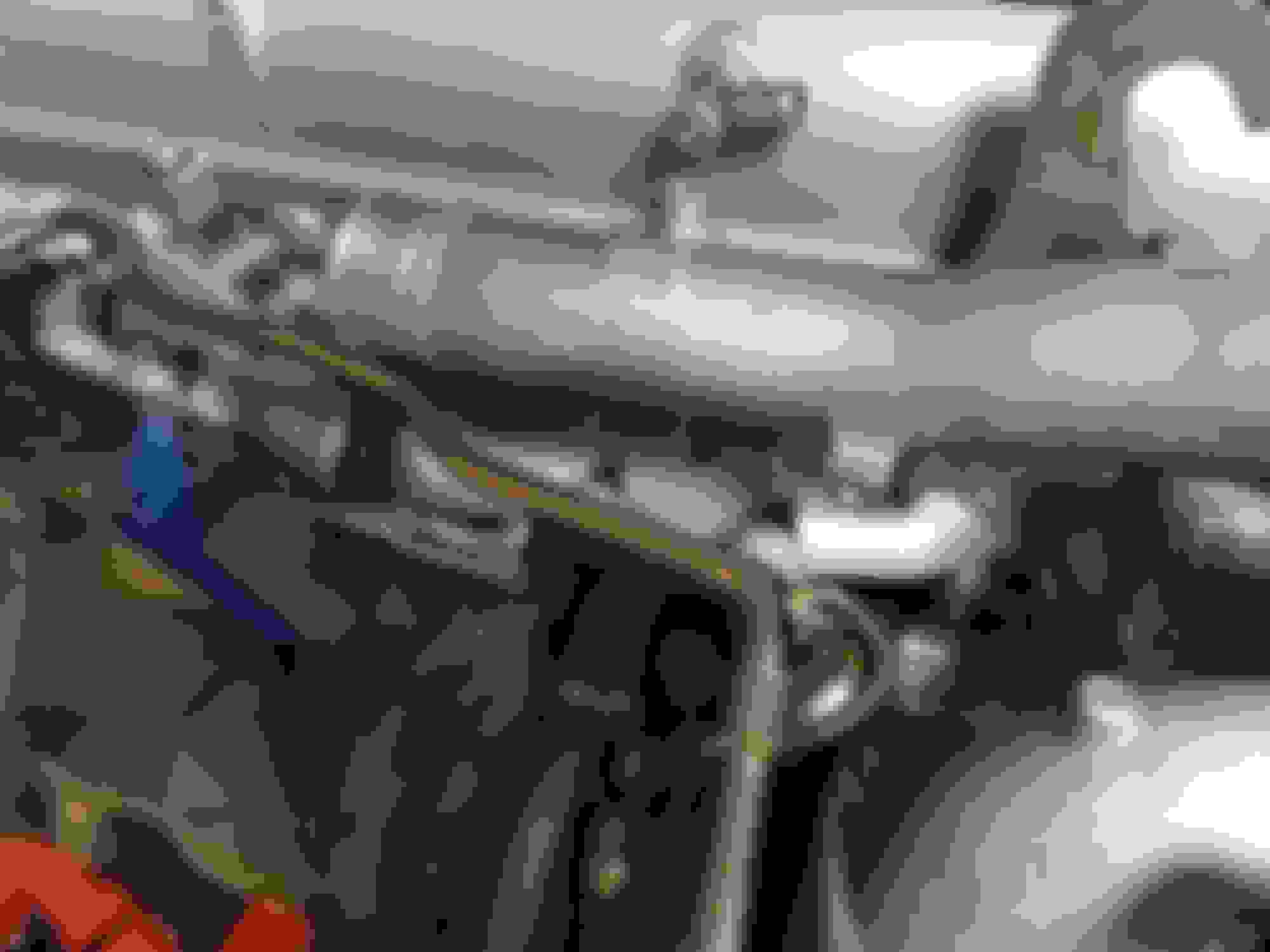
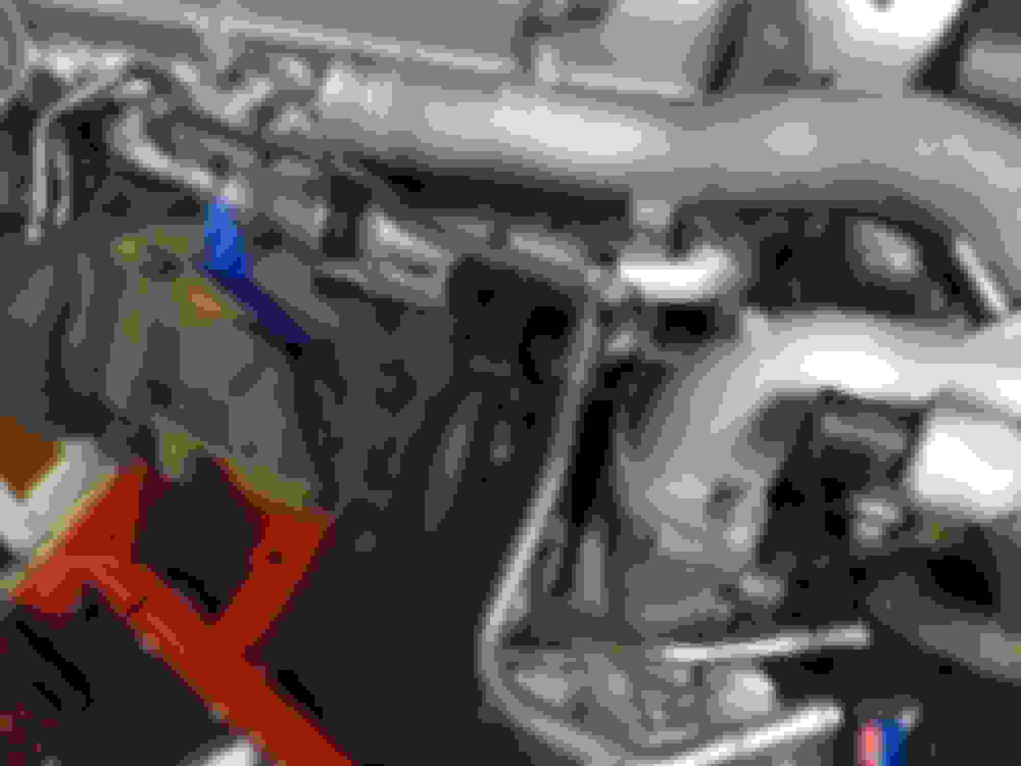
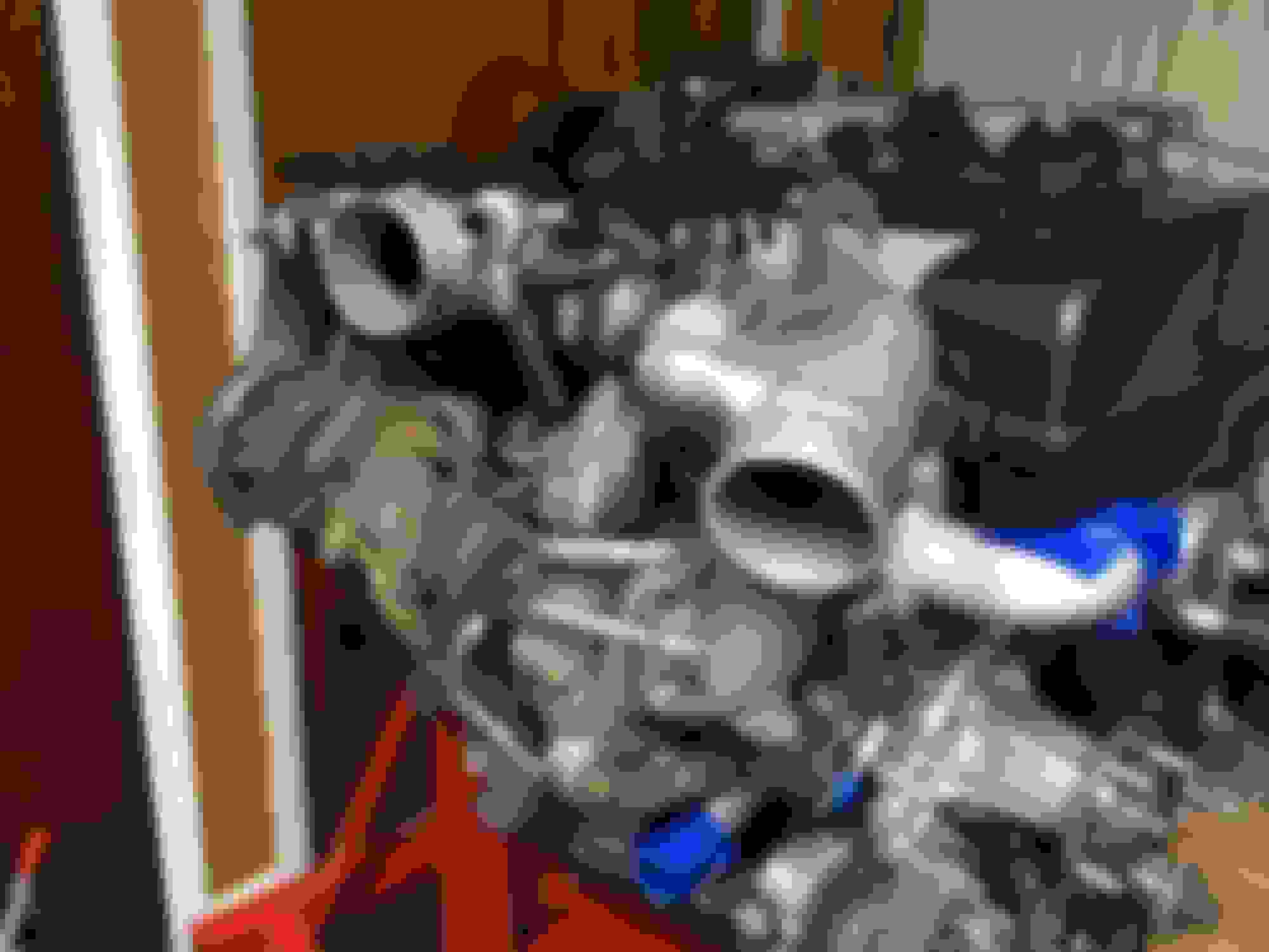
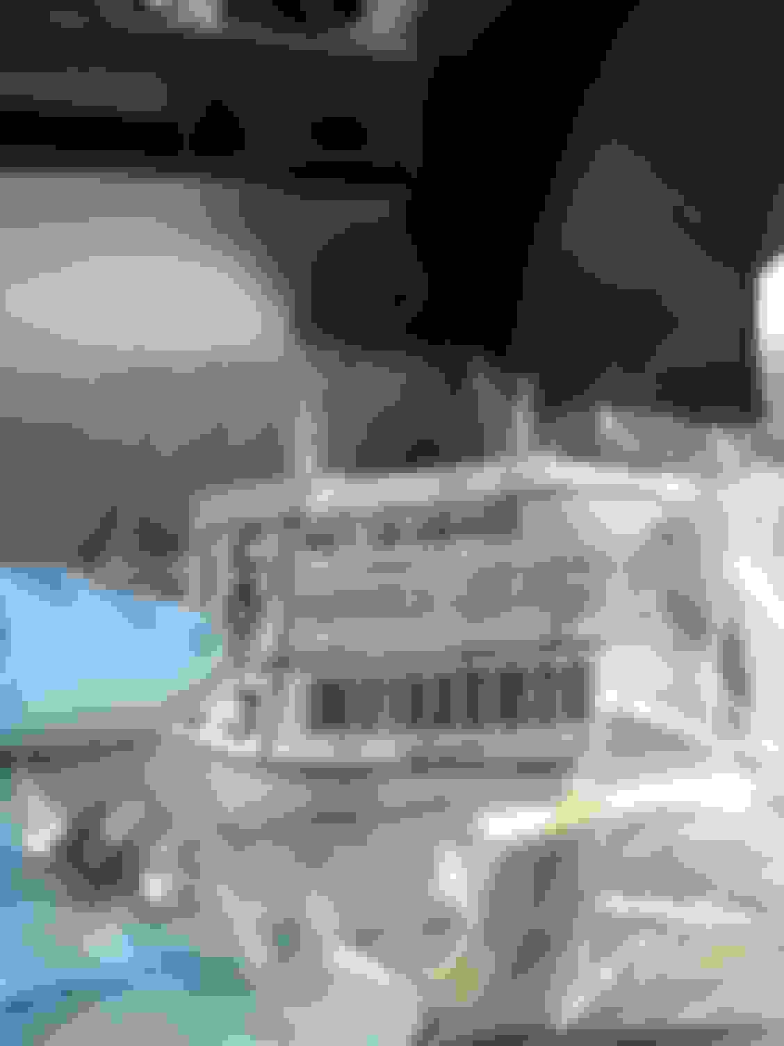
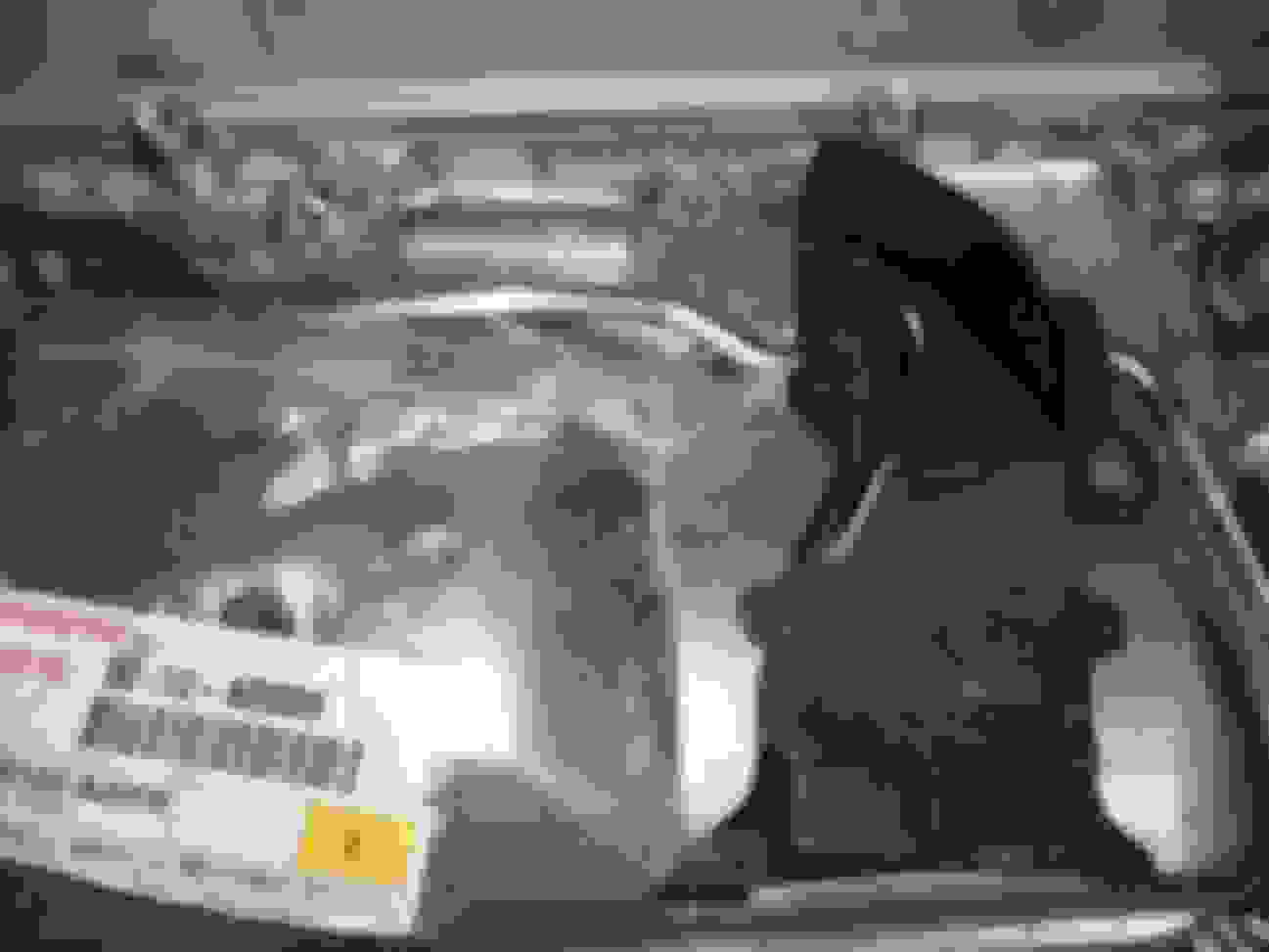
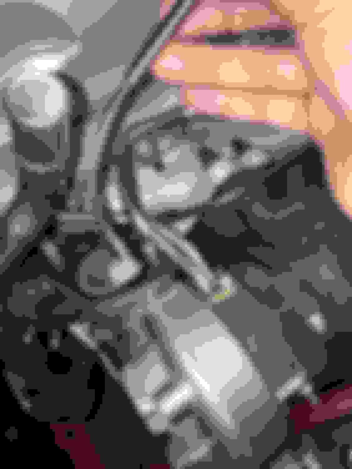
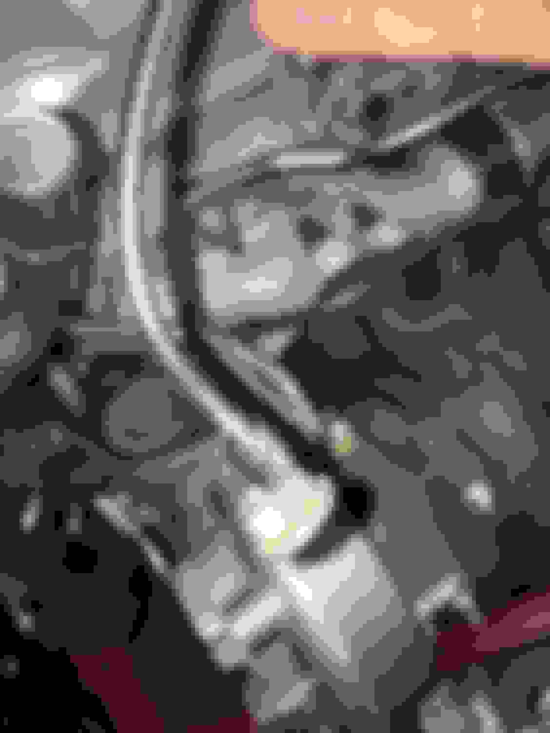
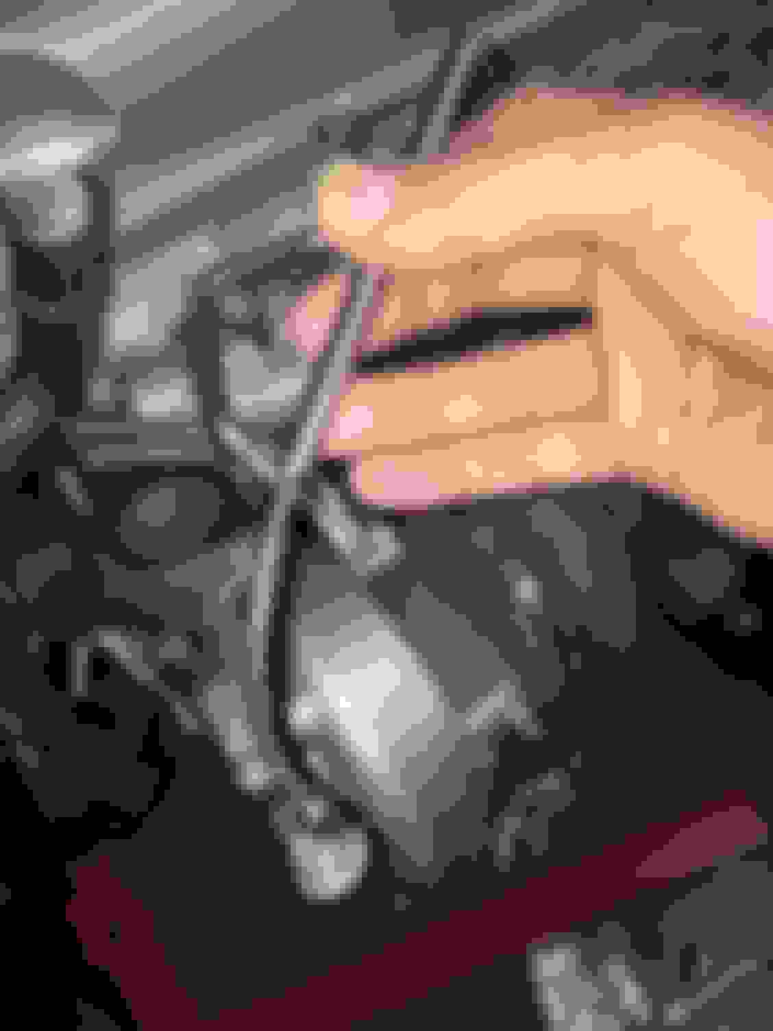
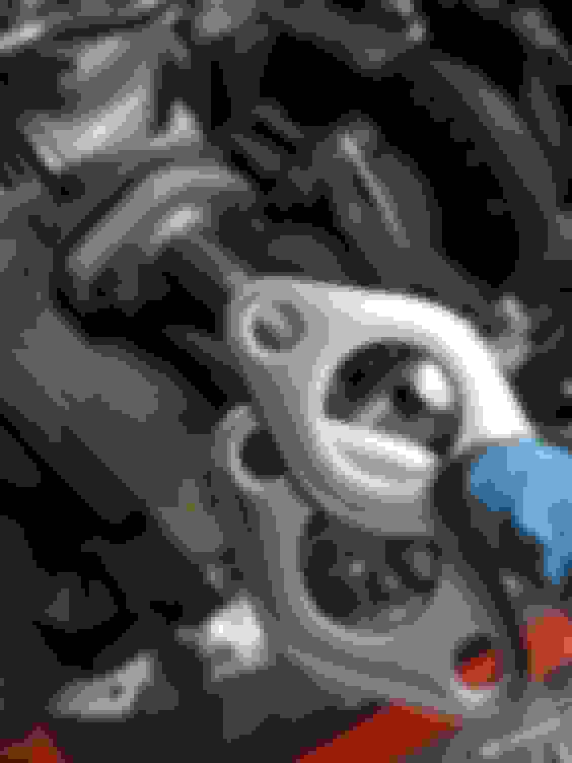
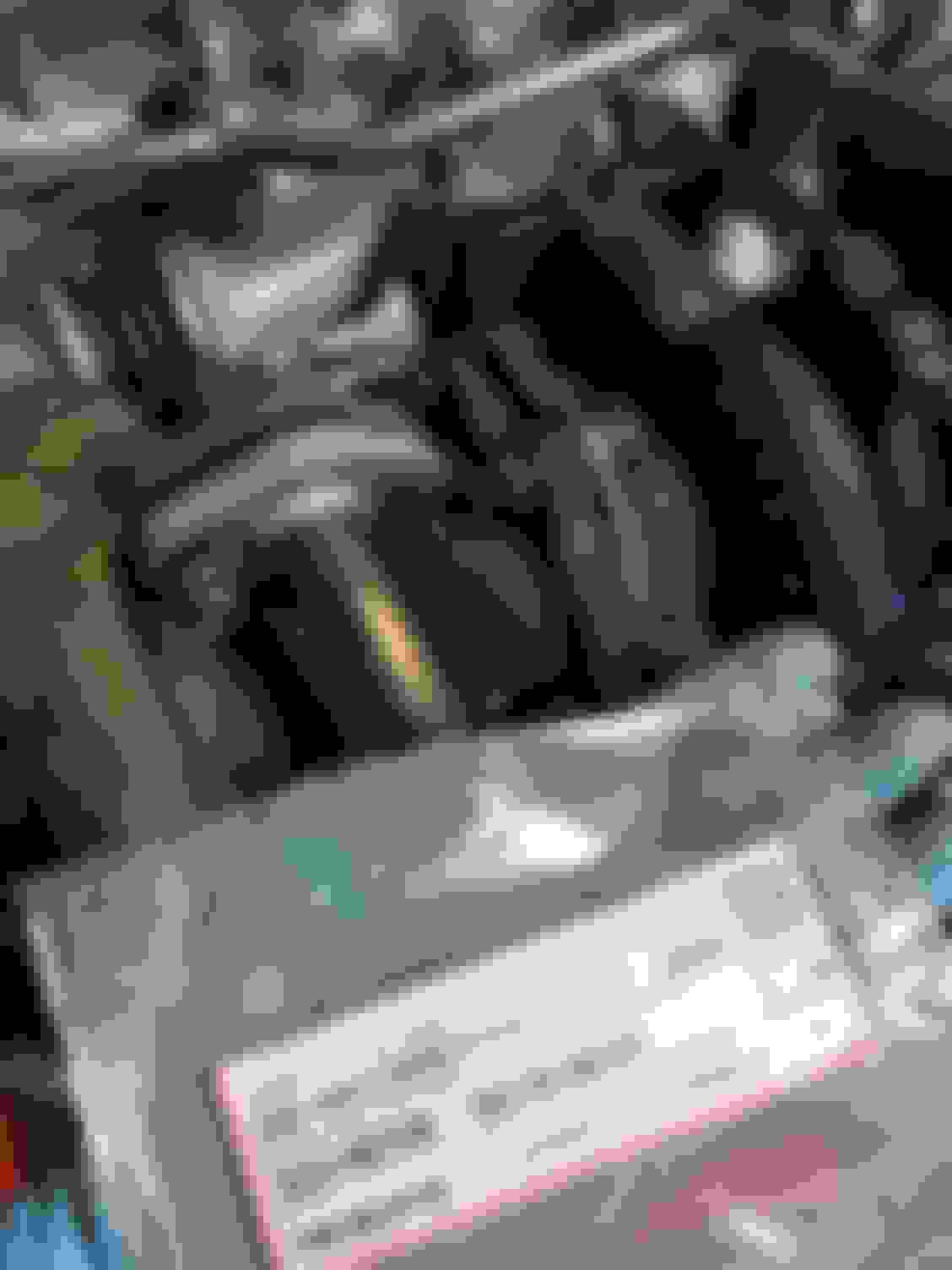
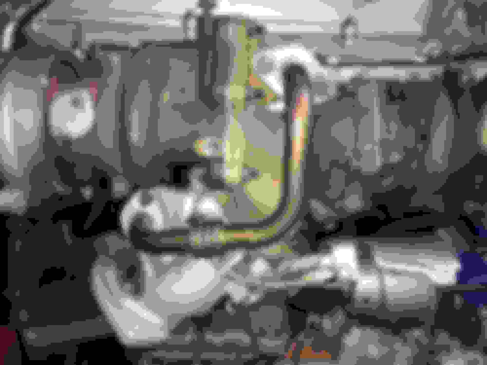
And here's a shot of the MKIV TT front sway bar installed in the SC300. It looks exactly the same until you see how the wide "U" shaped bend in its center is at a different angle compared to the SC front swaybar. I think it is this way in order to make more room for the MKIV's factory intercooler piping that runs under the front of the engine.
(^^ Yes, in the lower right of this image that is a factory Soarer Z30 TT SMIC intercooler bolted into the passenger side front air duct. It's been in there dormant for a while now ;D)
As for the real world handling difference, yes there definitely is one. It is subtle but you notice it right away. The front end handling is a bit sharper and more compliant. When I installed a 93-96 MKIV TT 22mm rear sway bar about six years ago I read the consensus as being that the rear sway bar change made the biggest difference (it does) and that the MKIV TT front sway bar was not needed. Well... it wasn't needed and handling has been great with just the rear upgrade... but now that I have the front upgraded I do agree with the impression of this SC owner who years ago took the time to make up a PDF file detailing how to install these in an SC. Here is a screen shot:
Another incremental improvement to the car that reminds me of what a great platform and design this thing is. I feel Lexus USA really should have had at least the major MKIV TT suspension parts (and 200mm Torsen LSD) repackaged as a factory sport package option on SC's. Even on the highway ride home and on some 35mph surface streets it's apparent that there is a subtle but definite difference if you have upgraded front and rear sway bars in your SC.
...
I will finish up the remaining engine build pictures soon. Early next month over the holiday season this swap will finally come together
Craig - if you are interested with a stock Supra MKIV rear sway bar ...you may have one that I have laying around when you drop by my place up North early next month.
Gerry, thank you for the offer (!) but I actually have had a rear TT sway bar and the TT subframe mounts in my car already It was one of the earliest and best changes I made from when I bought it in stock form several years ago I'm amazed I waited this long to pick up a front TT sway bar to match it. It really is true that the handling is better with just the rear bar conversion but even better with both the front and rear bars installed.
Are you running the TT or TRD rear sway bars on one or more of your SC's?
craig, thanks for the write up regarding the front sway bar. One of things I will be changing once my engine and trans go back into the car. I always love reading the posts you have, so detailed. Thanks for being an awesome forum member. Us green peas are lucky to have a guy like you on the forum!
Thanks Jim!! Truly though for me I'm always impressed with everyone else on the forum showing the creativity in their project SC's! It's me who feels like a green pea much of the time when I look at what everyone else is doing Have to say that the same goes to you, sir, looking at your perfection build.
A note on the MKIV TT front swaybar: I actually wasn't going to install one in mine if not for learning that it allows me to use the factory stock MKIV intercooler piping. I knew about the claims that it was better for ultimate handling but I'd been running the car with just the TT rear swaybar for several years. The stock SMIC piping was my main motivation.
I was pleasantly surprised and enthused when I noticed the front end control got subtly better. If you install the front and rear TT swaybars you will get a complete difference across the board but being used to the rear bar only for years now and now adding the front bar I can see the point. There is no night and day difference (like going to TT brake calipers).
I basically noticed that all my maneuvers were more stable and sharper, understeer was probably lessened a tad and overall the front end was no longer retaining its slight sloppiness (this was a subtle personal impression on my part prior to the front TT swaybar being installed).
I don't have anything exotic in my car's suspension, LSD or tire setup but I have focused gradually on improving the handling to that of a true GT. After having done this modification I am very happy with the handling of my SC and I think that aspect is completed. I keep going back and forth about whether I should go down from the 600 lb-in front and 325 lb-in rear linear-rate Hypercoil springs to the 500/250 linear Hypercoils I have had for the longest time but I really love the handling. Maybe... maybe I will change to the slightly softer springs and try to adjust my driving style so that the ride is a bit smoother on terrible roads... but once I am back on any good roads the ride is perfect and "OEM-like" quality and I don't feel like changing the springs any longer.
Maybe the answer in the future is a much more expensive coilover kit or an aftermarket magnetically adjustable shocks (like the system on the Camaro SS and ZL1) but for me only the in-cabin variable adjustment for poorly maintained roads would be the the advantage. As-is for the way I use my SC as a daily or every other day car I love the handling as it is
Just have to say again how valuable all the information and pictures you are including here are. Especially trying to look at old Supraforums threads with the same "info" but the photobucket pictures won't load anymore...this thread is invaluable.
Do you know the part number for the 6-speed throttle cable bracket that mounts on the intake manifold?
(EDIT: I think I found the part number: 78024-14140. The part # for the stay/bracket you have missing is 17125-46020 and appears to be discontinued and not available anywhere)
Keep it up!!!
mteele, thank you! Glad the thread has been of help to you! Providing a visual and notated documentation of this process to help others with whatever they could take from it has been my goal. All the pictures are stored on our local CL server so they should always be available. But all throughout I've tried to list the other threads that I have learned from as well. Everyone who has made threads on CL and SF have contributed a lot to the community!
I actually did not have the part number written down for that 6-speed throttle cable bracket-- thank you! The stay bracket I did find eventually and I believe I show it being installed a few posts back.
The progress has resumed again as of a couple of days ago. I have plenty backlogged to catch up on here and I'll try to get that moving along shortly.
Where things are at right now... the engine on the stand is now complete apart from very old placeholder ignition coils and the front accessory system still missing (which will be partly completed with accessory drive parts from my GE engine). I'm starting on the harness wiring now and at Gerrb's suggestion moving ahead with the swap in a few days before the harness conversion/restoration is completed.
Sorry for the delay in catching up on the build so far, folks. Today I'll cover the rest of the USDM twin turbo assembly onto the engine.
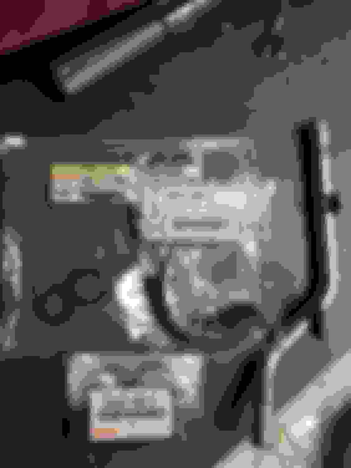
CT12b oil return lines
For these I decided to use some very fine sandpaper to remove any surface rust on them and then apply a light coat of VHT high temp gray primer and some VHT high temp black. I made sure to keep any paint away from the inside of the pipe passages. These, along with any of the other VHT painted parts will cause some initial smoke once the engine is first started as part of the paint curing process but it is still better than just leaving the bare metal bare from the sanding.
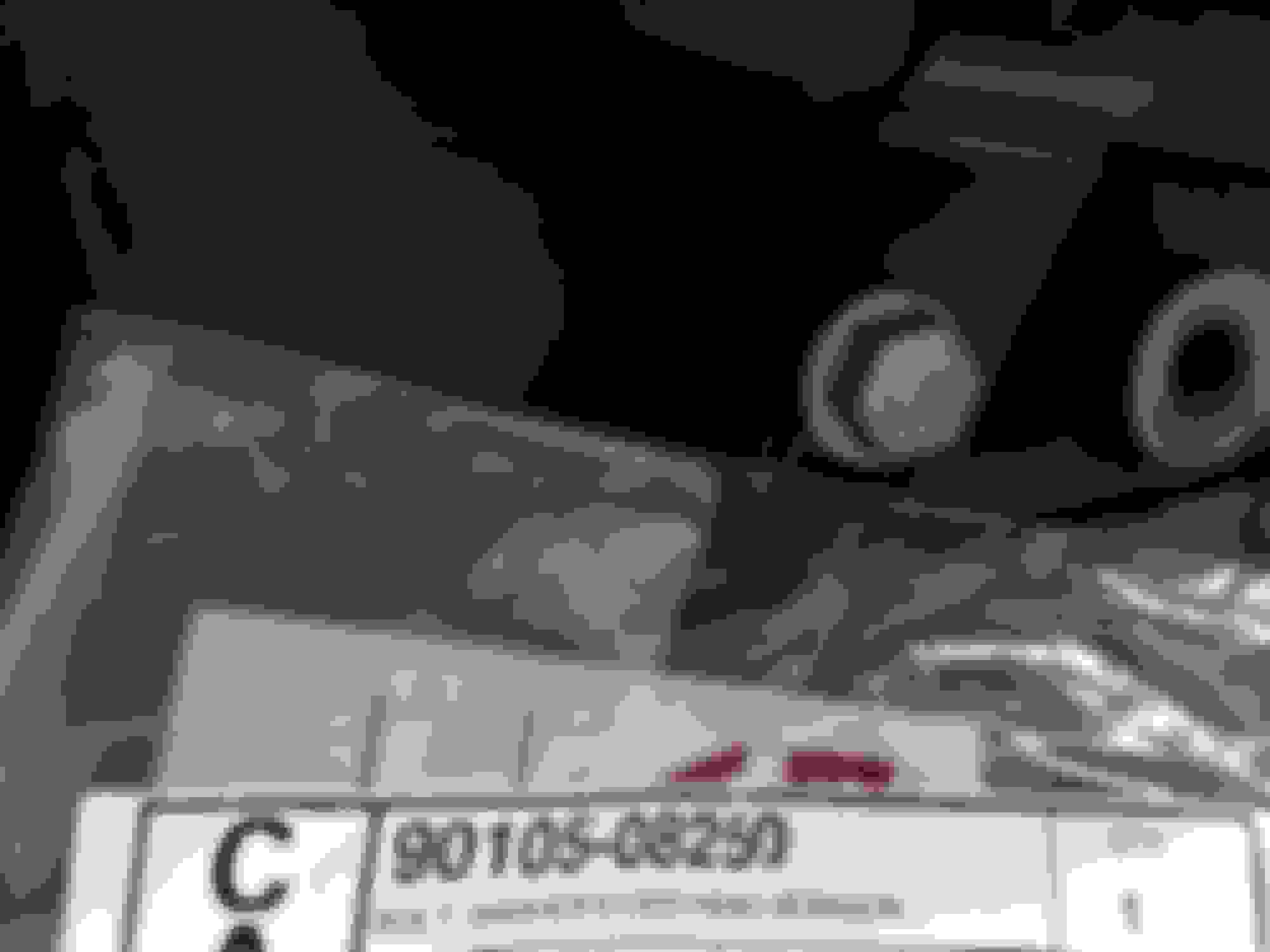
There is a small bracket that attaches onto the rear of the two turbo oil return pipes. It uses bolt 90105-08250 to secure to the engine block. The exact hole that it goes into took some experimentation to determine without a direct visual example handy.
The MKIV TSRM from EG-150 "TURBOCHARGER SYSTEM" covers the installation of the turbo oil return pipes (and the stays on the turbos if not previously covered in this thread):
CT12b rear turbo water bypass pipe to upper rear water bypass pipe (nearly vertical)
I believe the torque requirement for the two bolts holding the aluminum pipe to the turbo compressor side is 15 ft-lbs. I will have to double check that in the TSRM.
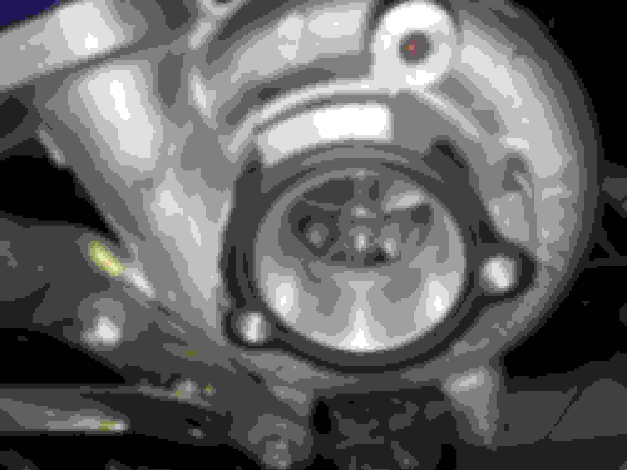
CT12b front compressor side aluminum pipe with gasket
This also, I believe, takes 15 ft lbs for the two bolts
CT12b long upper cooling lines from rear turbo
This was a bit tricky for me and the experience for others may vary. My steel lines were not exactly in their original shape and had clearly been bent around a bit when they were last removed from a working turbo system. This underscores to me how important it is to dismantle the stock twin system in the prescribed order in the TSRM because you might be tempted to skip on a couple of steps to make removing these lines a shorter process but they have to be fiddled with a lot to get them off the turbos if that is done.
The end result, at least in my case, is spending a good hour or so carefully bending the steel back into a decent enough shape to allow for all the original clearances of the heat shield, some bolts that need to be accessed on turbo #2 (rear), the clearance of the lines from the front aluminum charge air pipes, the mounting points for the front of these steel lines and finally the placement of the water bypass hose connections at their ends right next to turbo #1 (front). It was something of a process. Moral of the story: dismantle the stock twin system whether JDM or USDM in accordance with the TSRM procedure
Connecting hose and clamps for CT12b front air charge aluminum pipe to "Reed Valve" unit
I'm still not entirely sure what the so-called "Reed Valve" does but this and essential part of the sequential system. This is a very thick heat resistant hose that connects to the aluminum unit containing the Reed Valve.
Turbo top vacuum hard line assembly (black painted) & rubber couplers to main air intake pipe
Small bolt(s) to affix top vacuum hardline assembly:
Couplers for main turbo intake pipe (for the air cleaner assembly):
But after having done this I have to backtrack just a bit. What you're actually supposed to do is install the heat shield before you install those parts on the top of the turbo charge air piping.
That also includes two small 90080-12001 studs that go into the two threaded holes shown on the exhaust manifold. The turbo heat shield goes on first and then the charge air piping goes on and finally the small periscope-like heat vent goes in this location with those two studs.
The turbo water line can be fiddled with slightly to get the heat shield under it but everything else will be in the way before that goes on. Then there are two small bolts to affix the periscope-like heat vent to the exhaust side valve cover (90119-06493):
And then there are two nuts that go onto the studs the periscope-like vent guides onto:
Last edited by KahnBB6; 02-26-21 at 02:37 AM.
Reason: Minor correction
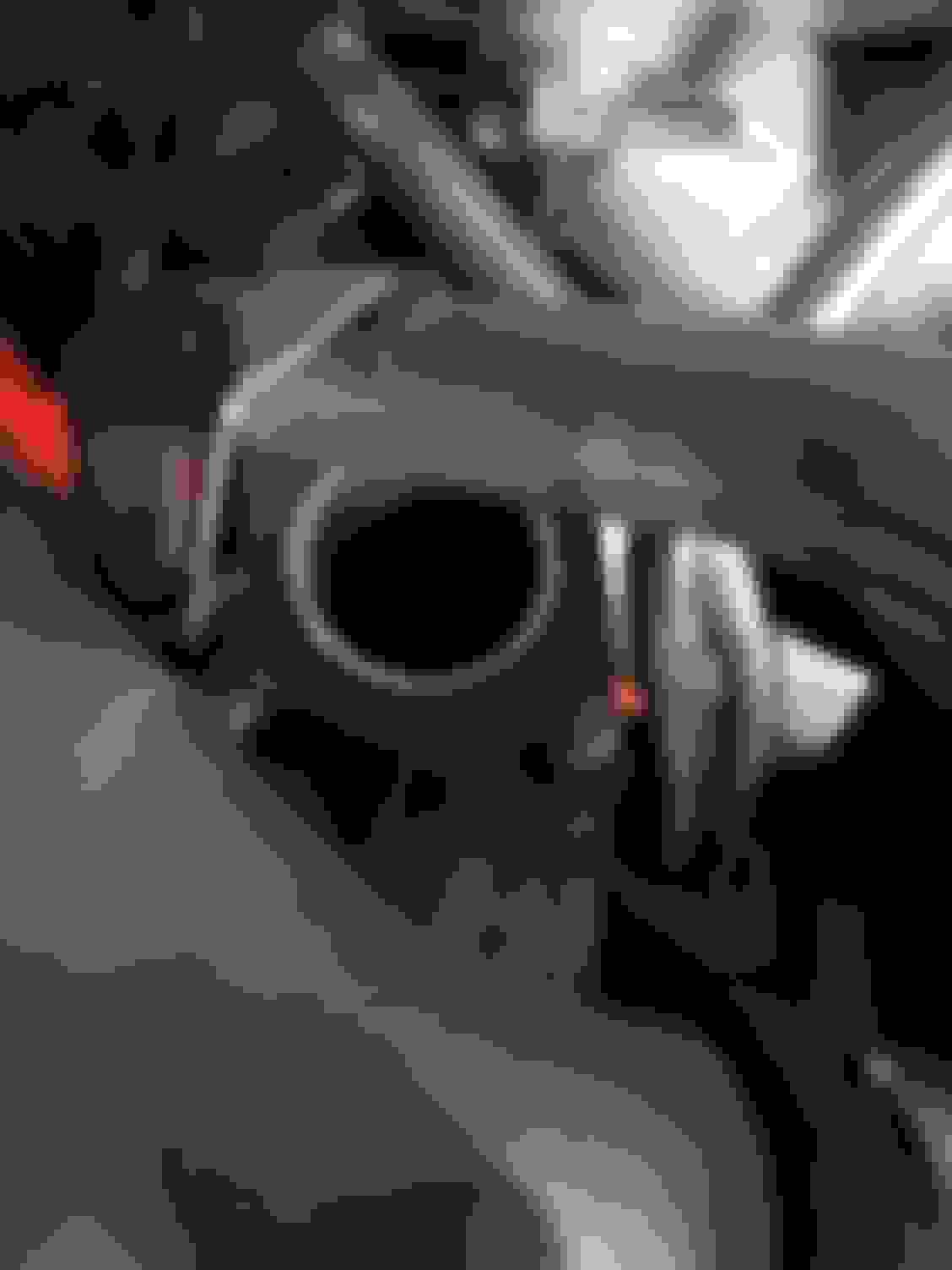
How to retrieve a small nut that annoyingly fell INTO one of your turbos:
Boy, this was a chore until I had the right tool. I accidentally dropped a nut into the top most compressor entry opening in my #2 (rear) turbo. I had a straight retractable magnetic tool on hand but in this case it wasn't going to do the job and no other small tool I had would reach the nut. I needed something with a curved angle and a magnet on the very end.
Waiting for a nut to kill the compressor blades the moment the engine has started up would be a terrible thing.
I ordered a couple of special magnetic tools from ebay and Amazon to reach the nut with a curved angle but they weren't very good. What eventually worked was this very nice bendable AND retractable magnetic tool (Lisle Model #66540) that I picked up at an Autozone:
This is really one of the best small tools I have ever found! I highly recommend this for anyone's personal tool kit.
Once I had the right extraction tool it only took a moment to rectify the snafu:
A couple of the nuts to connect the lower turbo collector were not looking great so I replaced them. They are 90179-10167. The three nuts require 51 ft-lbs of torque.
Then there is an oddly shaped cast steel support "stay" (17883-46011... I think) that goes a bit behind the lower collector assembly with two bolts (90105-10417). Those bolts take 32 lb-ft of torque each.
Then the small steel turbo #1 to turbo #2 transition pipe mounting area requires two studs... as does the sub-heated oxygen sensor #1 location. Both required studs are the same (90126-08009).
And two metal gaskets are required for the turbo transition pipe. Sorry, I don't have the part numbers for those as they came as part of the OEM USDM turbo gasket kit.
NOTE: the metal gaskets aren't in place in every single one of these photos but that was just because I was not ready to install the pipe when the photos were taken. You must have these metal gaskets for the steel turbo transition crossover pipe.
Four nuts (90179-08101) are required to torque down the transition pipe with 18 ft-lbs
 11-12-17, 10:23 PM


 Have to say that the same goes to you, sir, looking at your perfection build.