When you click on links to various merchants on this site and make a purchase, this can result in this site earning a commission. Affiliate programs and affiliations include, but are not limited to, the eBay Partner Network.
De-Rusting of some turbo side parts (prep for paint)
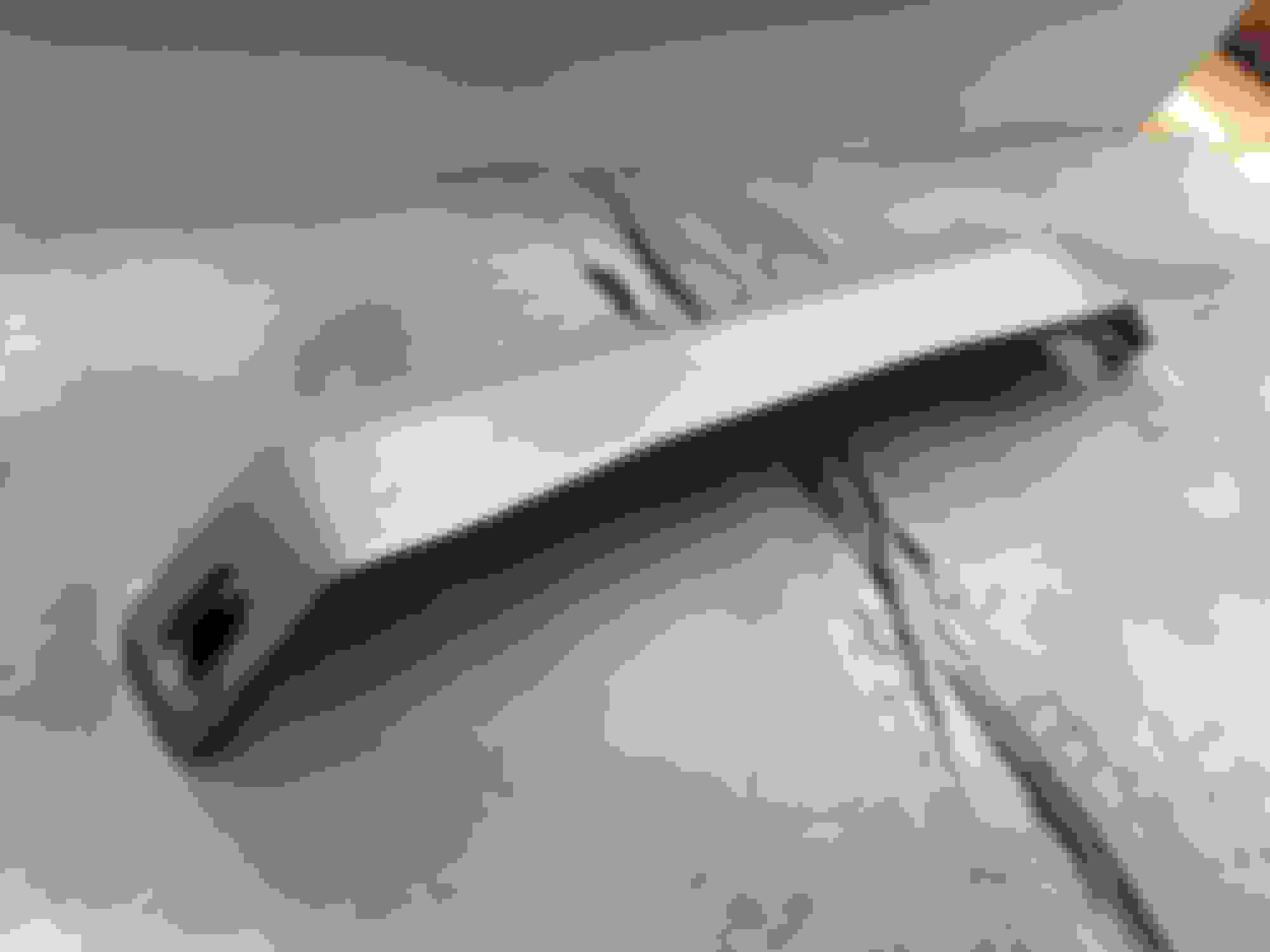
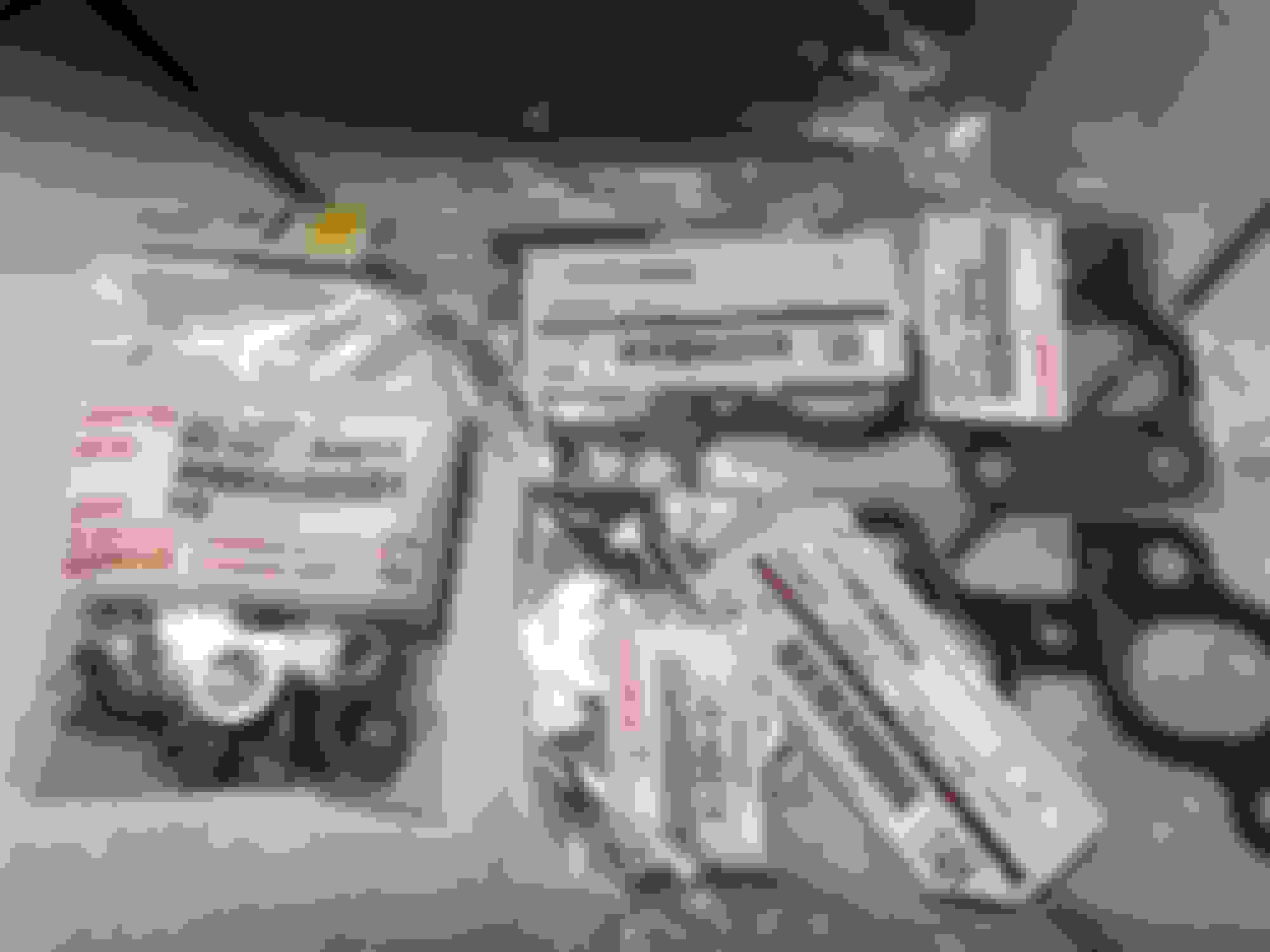
I didn't want to get into unnecessary work but some of the surface rust and pitting on these cast iron parts and even some stainless steel pipes really bothered me. If I'm assembling an engine I plan to keep in service for years, can I expect this rust to get any worse? I don't feel like chancing that.
An example:
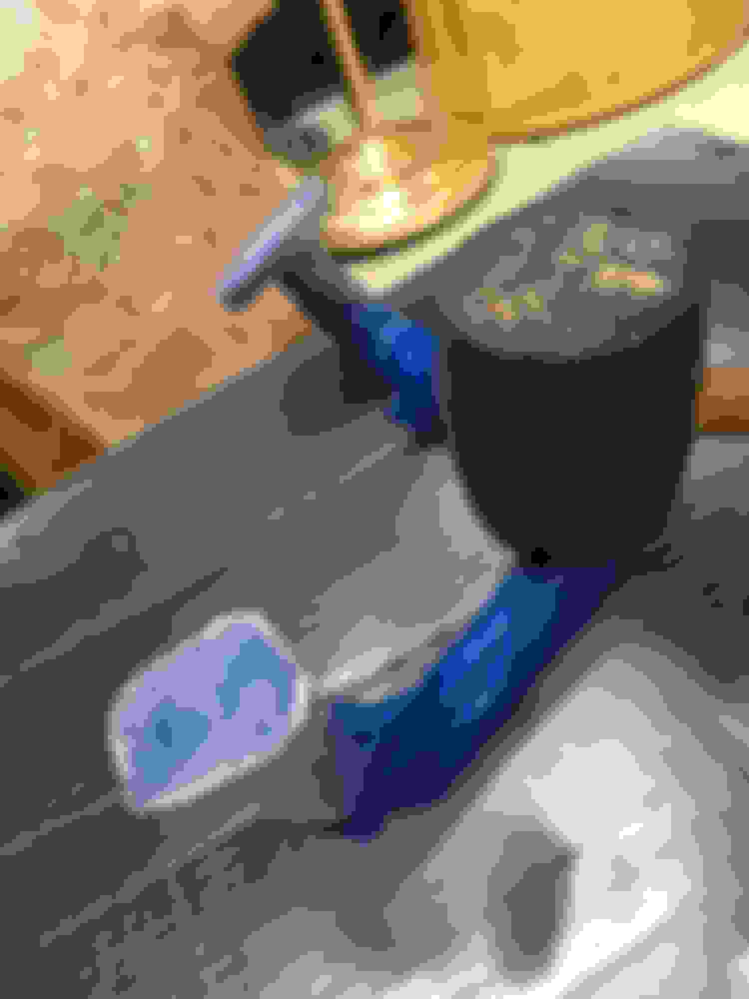
And so, I decided to use a highly recommended non-acid rust bath solution: Evap-O-Rust.
Tractor Supply and a few other places carry this but it's not easy to find. A more common (albeit still pricey solution) is going to your local Autozone and buying Metal Rescue which is a concentrate that mixes with one gallon of water each.
There was so much de-rusting to do I used a couple of Evap-O-Rust bottles and a handful of Metal Rescue concentrates when I couldn't source any more Evap-O-Rust in a timely manner.
The USDM 2JZGTE stock twin exhaust manifold was first. I took some light Dremel wire brush to its surfaces to remove anything easy.
And then the exhaust manifold and some other parts with some hard to remove rust were left in the solution for a couple of days and rotated every so often.
Note: with these non-acid rust remover baths you do have to wash off the surfaces of your metals that were exposed to the solution. You don't have to when you're actively dunking and rotating to get the rust removed but eventually you want them wet with the solution and then you want to wash them off with water to minimize some mild yellow discoloration.
Almost all of these cleaned parts would get primer and paint later anyway so that is another way to finish them after they've been treated.
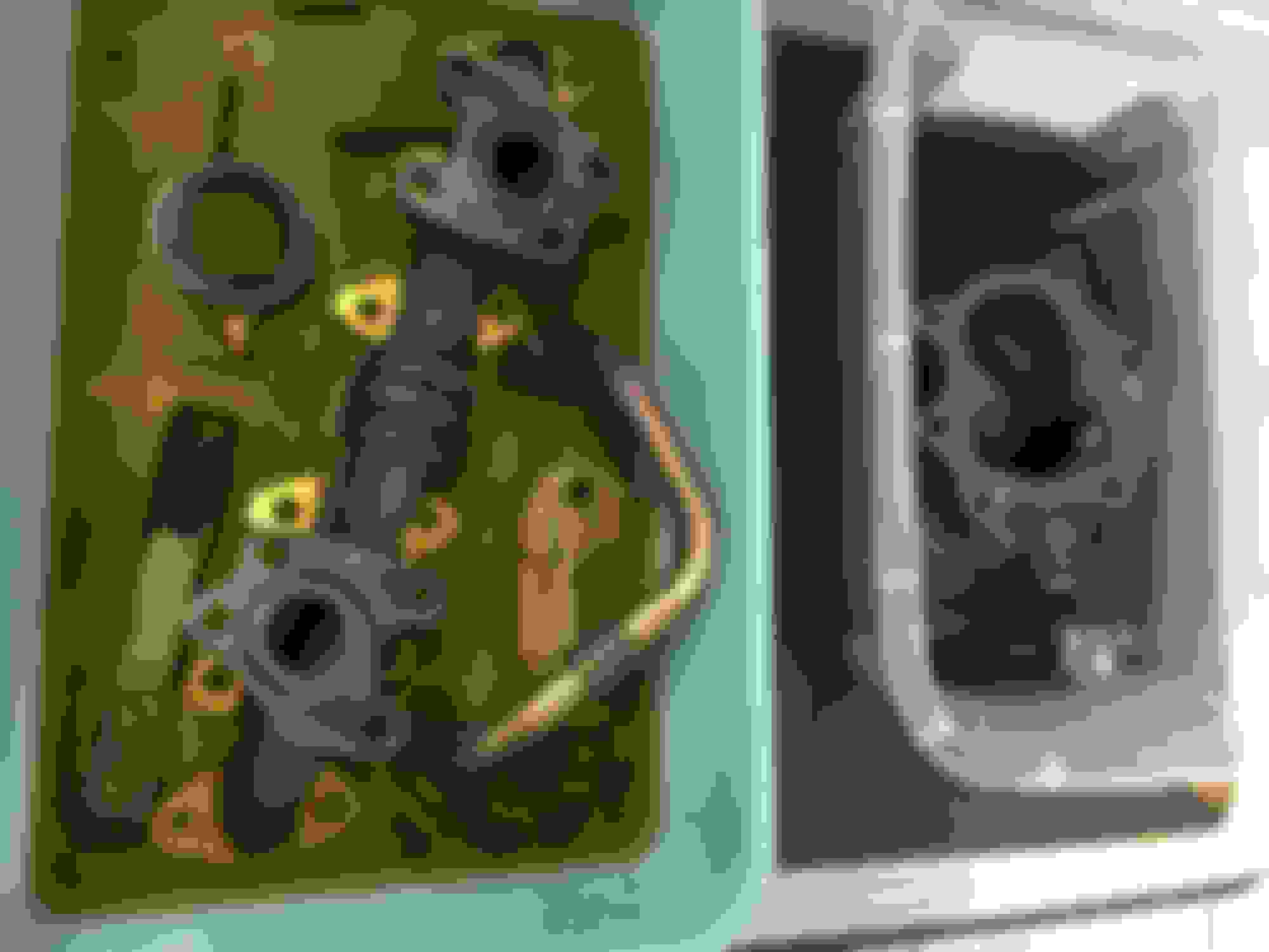
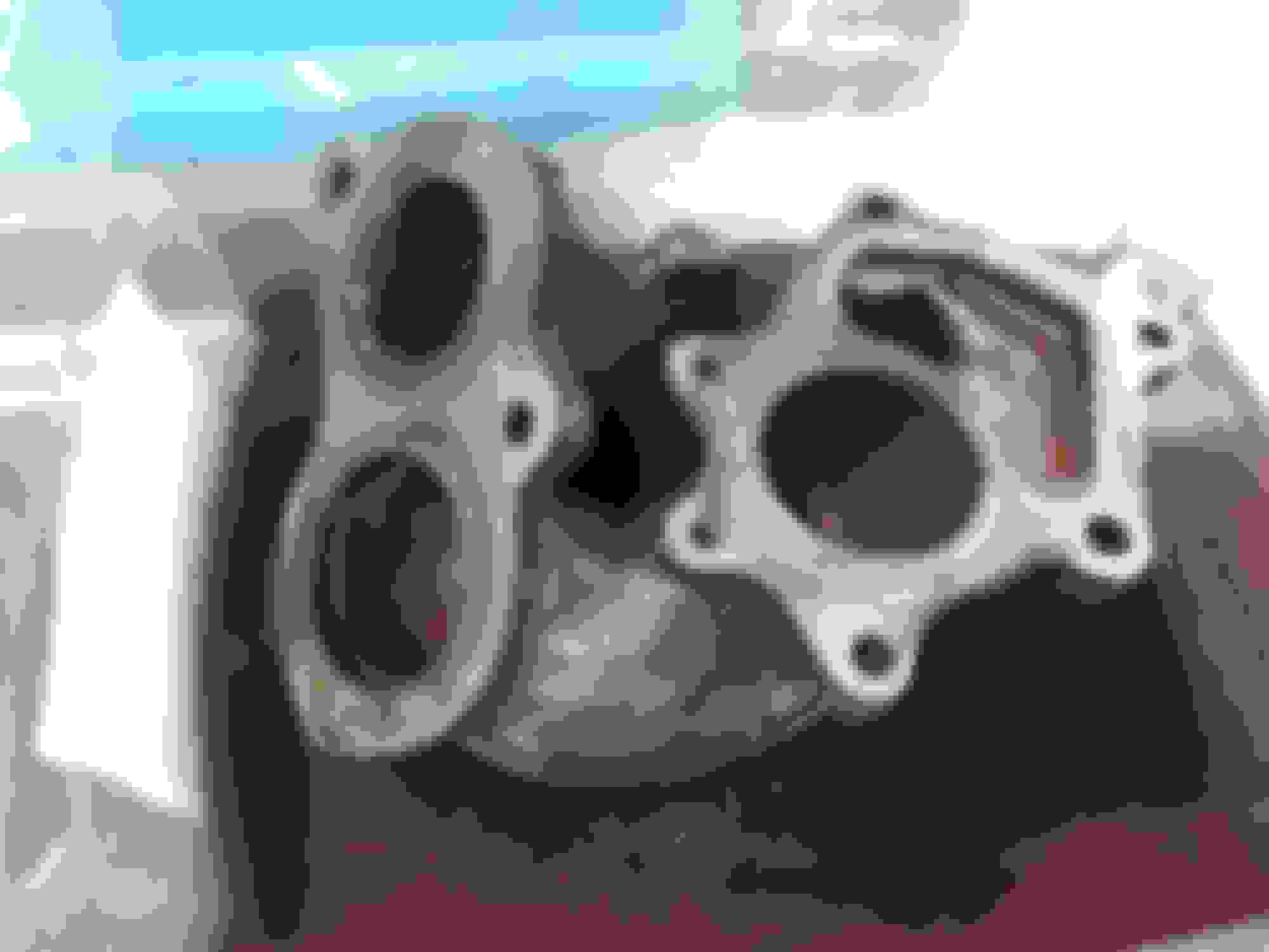
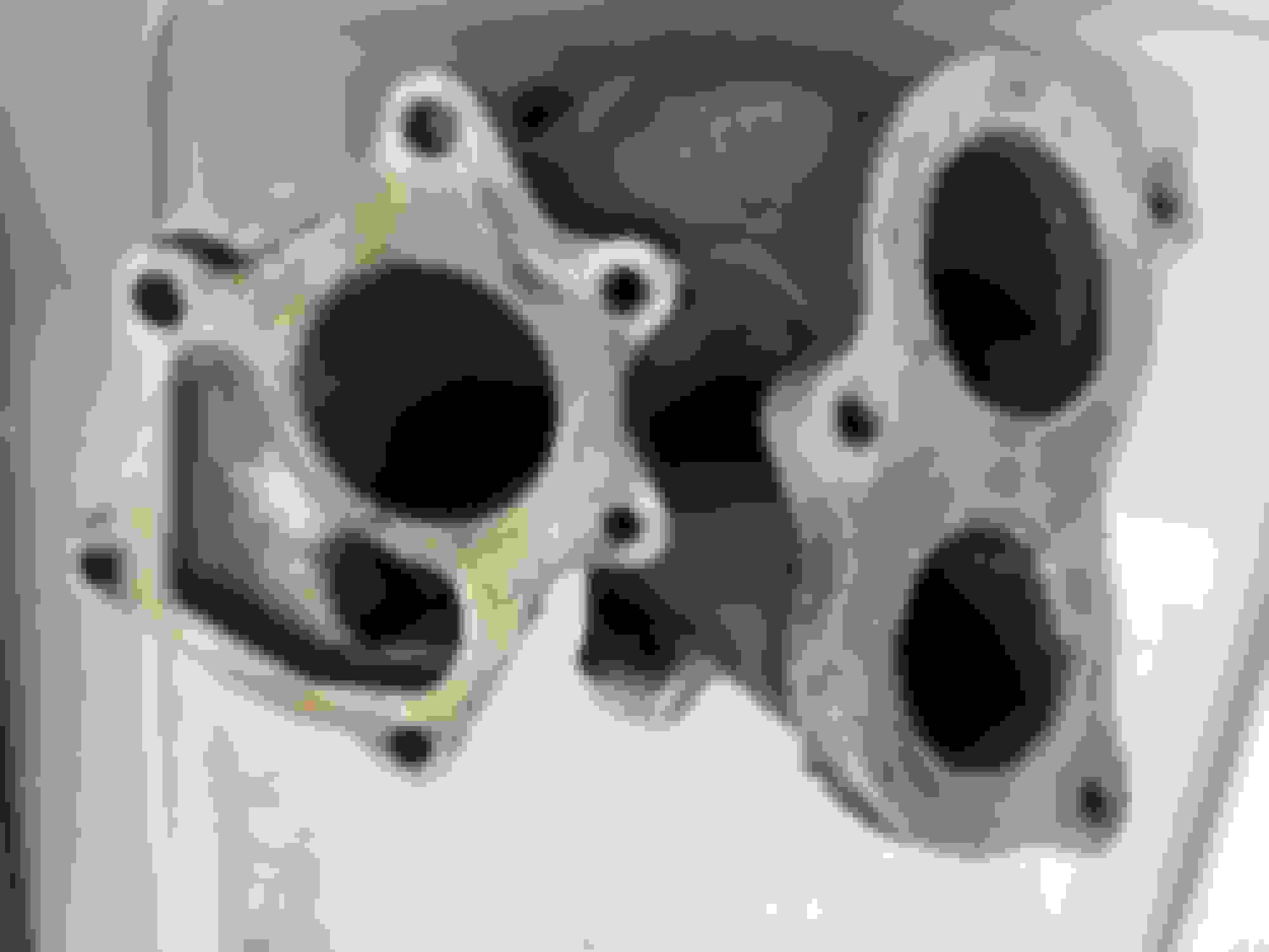
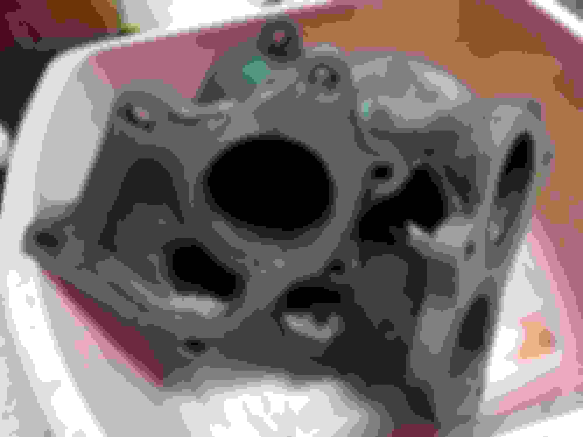
Removing the wastegate arm that holds the ceramic valve in place on this Y-section exhaust combiner. There are two metal gaskets that have to be replaced on either side of this ceramic valve. One was so stubbornly stuck in there I have to gouge it out from the surrounding iron housing.
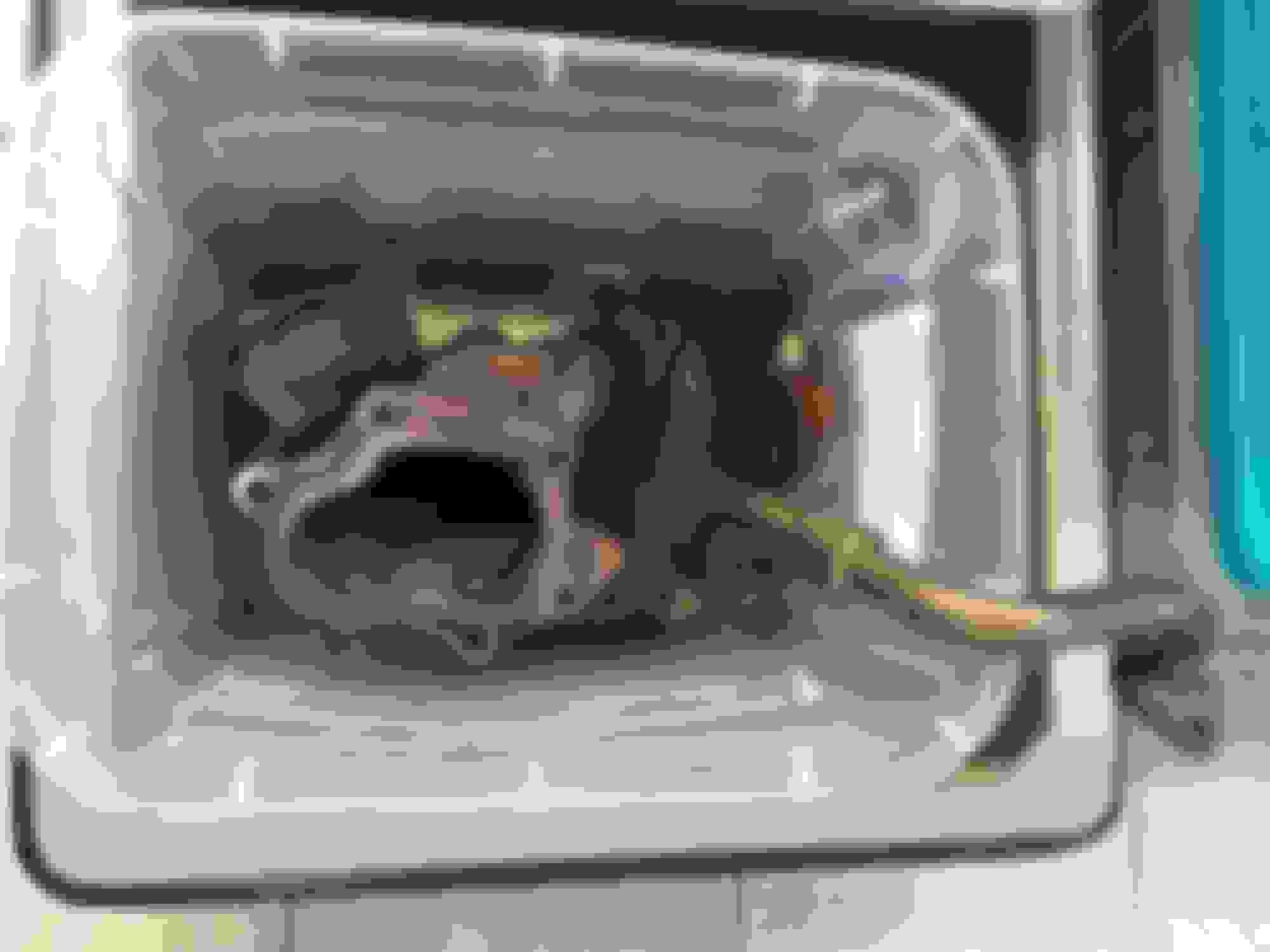
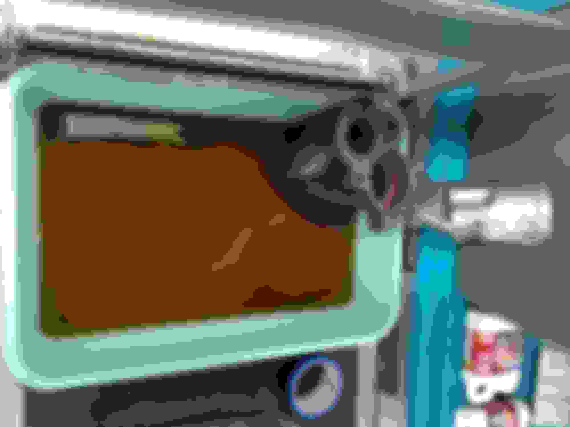
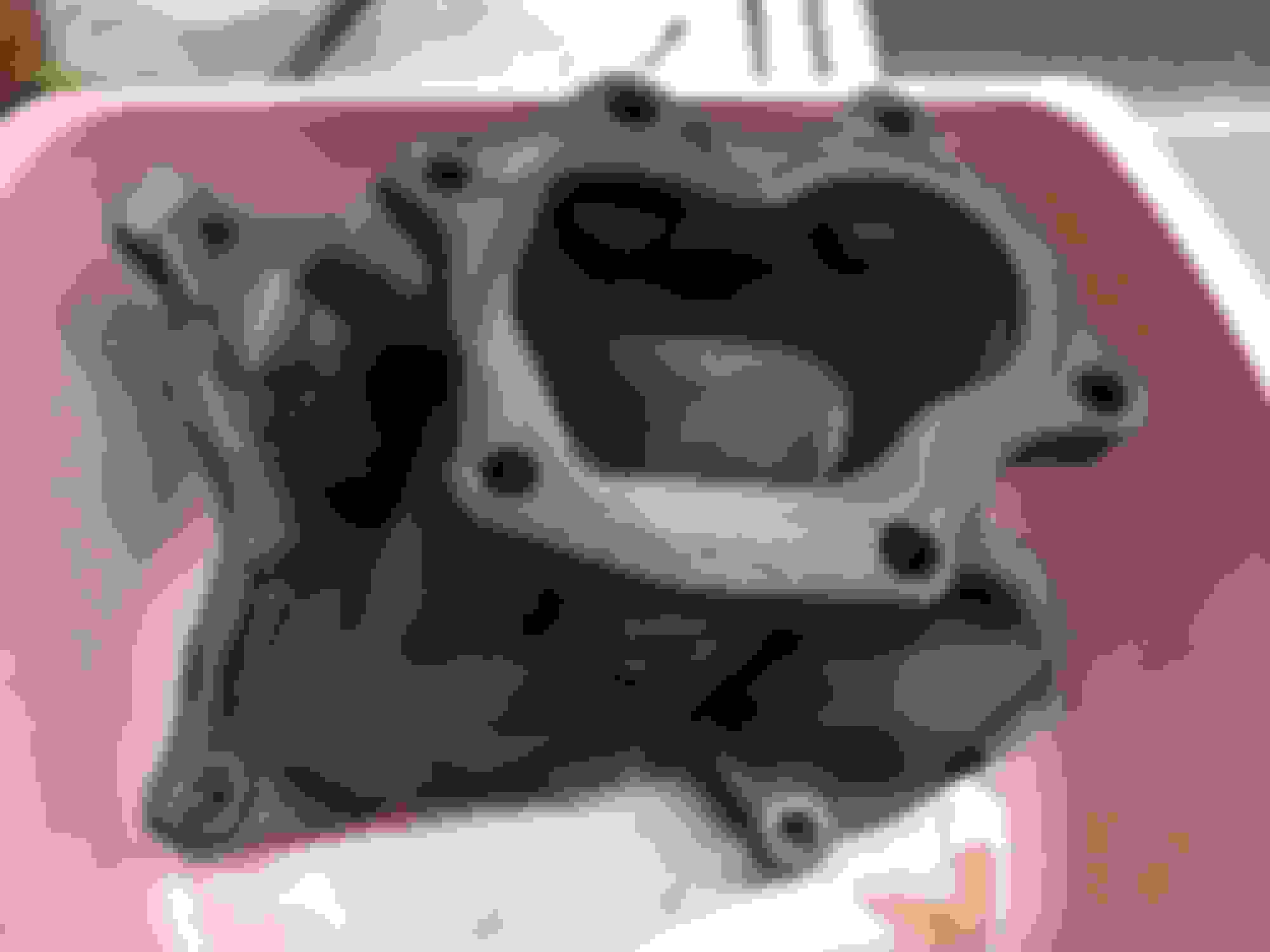
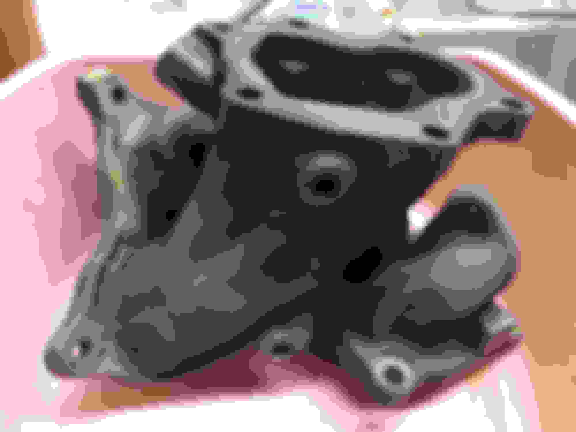
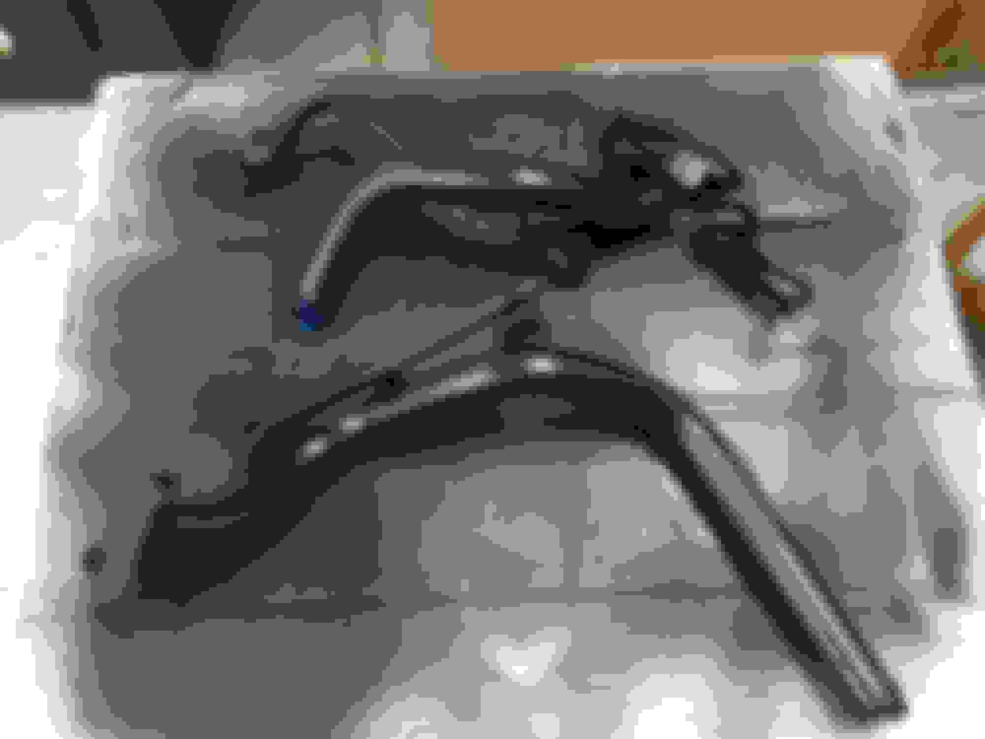
Additional rust soak for the iron turbo #1 and turbo #2 combining manifold
This first and second turbo exhaust mating section "Y" took a lot of solution bathing before most of the bad surface rust had been removed.
Paint for some turbo side parts
I am not an experienced painter of engine parts. I've used easy spraycan primers, paints and clearcoats on a number of house projects over the years and without any really dedicated space or a non-food-purposed oven this is about as advanced as I was going to get.
Since engine temperatures can get pretty high I went to Autozone and picked up some appropriate VHT Flame Proof spraypaints, primers and clear finishers.
For anything that wasn't directly part of the turbo assembly I used 500F paints. For anything that was part of the turbo assembly I used 2000F paints.
Everything got a coat of primer first. In some rare cases such as with little brackets that were stubborn I used a high speed metal wire brush on a stationary motor to physically remove any lingering oxidation before going into a primer coat.
One thing about these paints, or at least the 2000F variants, is that they are intended to be baked in over several heat cycles either in an oven (which I did not have) or on the car.
Since this is going to involve an engine break in procedure the moment these paints are exposed to heat I hope I can follow the directions they want for the bake-in process to take but I am not going to risk my new engine and deviate from a break in procedure just because I am afraid of some header paint chipping prematurely.
When restoring a car or an engine you do the best you can
The USDM 2JZGTE sequential turbo header ready for masking:
Turbo header masking. This took a while to cut out all the painter's tape to cover all the surfaces that should NEVER have paint on them:
First and second primer coats applied:
After 2000F silver paint and a 2000F satin clear have been applied:
Brackets and pipes:
The sequential transition pipe above got some overspray on its mating surfaces despite my best attempts at masking with painter's tape. If this happens to you the overspray MUST be removed from the mating surfaces. I used some very fine sandpaper and very light application of a Dremel wire wheel. You don't want to dig into these surfaces. You just want to remove the paint that shouldn't be on them.
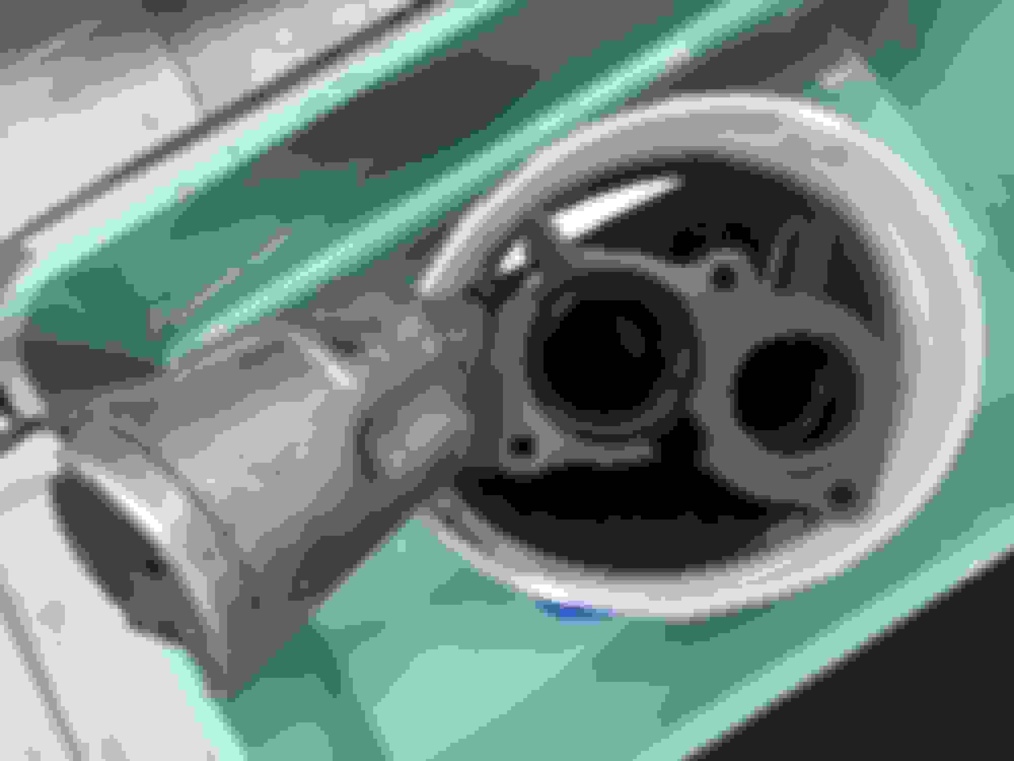
With the header painted I installed it on the block with a new set of gaskets and a new set of ceramic(?) round gaskets at the two turbo inlet ports.
The header has a pre-defined order to torque its nuts. Some of those nuts are very hard to reach and require some special socket fittings or a crow's foot to get at them and still follow the order Toyota wants.
Each stud nut gets 29 ft-lbs but they all have to be torqued town in sequence in several passes.
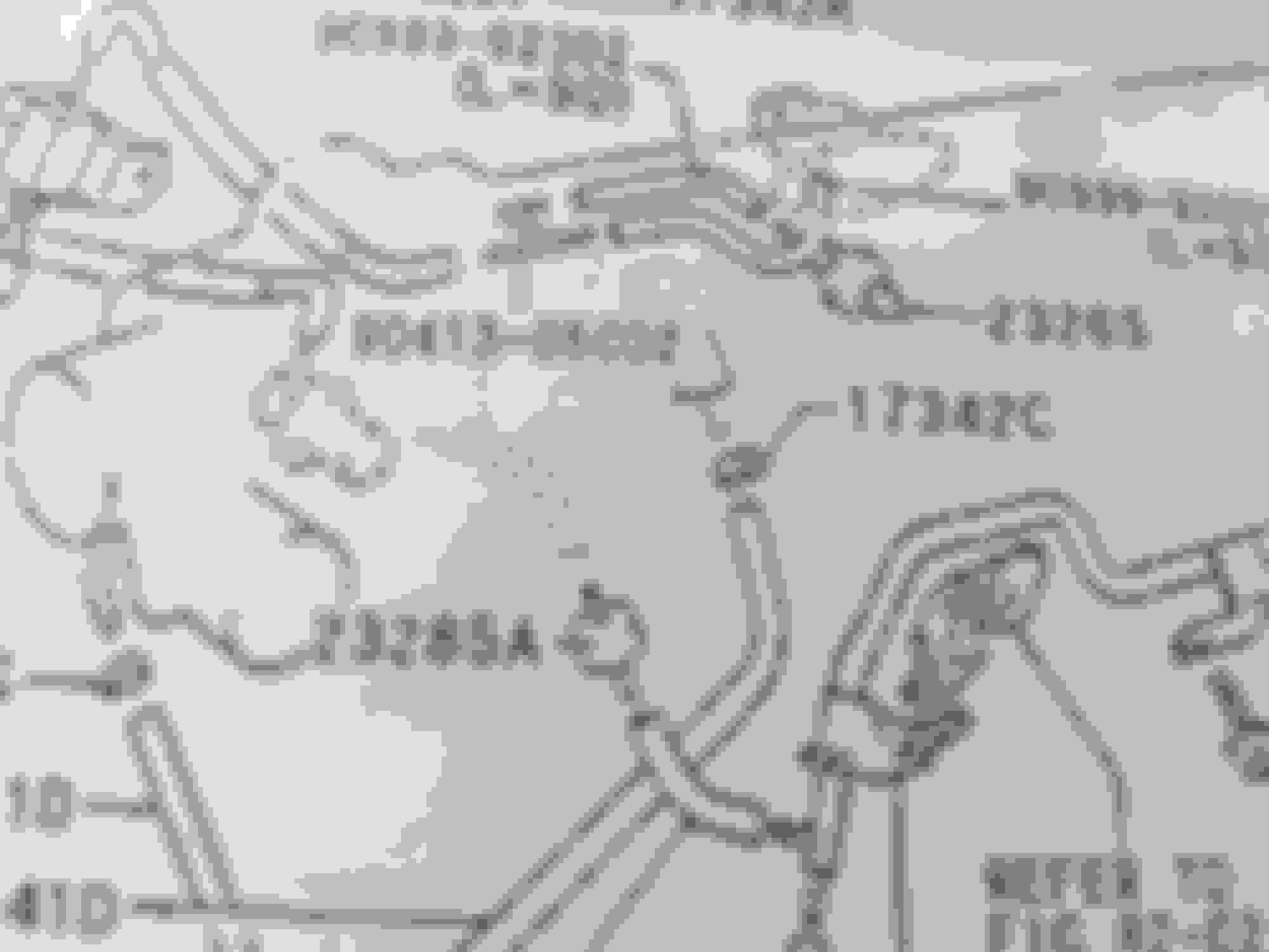
Here is how Toyota wants it done (MKIV TSRM EG-71 "ENGINE MECHANICAL"):
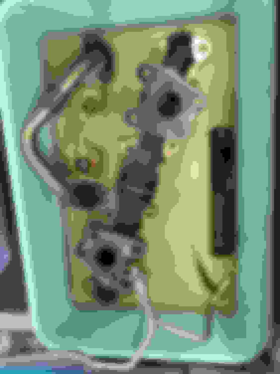
This is one of the more confusing parts of this stock build which I could only find so much documentation on. It will be abundantly clear if you already have any 2JZ-GTE complete engine waiting to swap in but building from scratch it wasn't immediately clear how the hoses are meant to be routed.
... Aside, what the evaporative emissions system does (in conjunction with a charcoal canister-- the 2JZGTE's is different from the ones found on 2JZ-GE's) is curb any raw fuel odors by absorbing any gasses coming from the fuel tank, running them through what is basically fine and densely packed charcoal and depositing what comes out back into the intake tract to be burned up in combustion (I think I have that right).
That raw fuel smell is what this system is designed to curb. That's all it does. I think most such systems use a VSV of some kind or another way of implementing a controlled on/off valve into the system.
...
The way Toyota designed this into the 2JZ-GTE requires both the BIG intake side manifold "stay" and the little intake side manifold "stay" both having metal pipes built into them.
Most of this can be plumbed using Toyota 90999-92002 cut-to-length short hoses or Gates #27042 5/32nds inner-diameter hose.
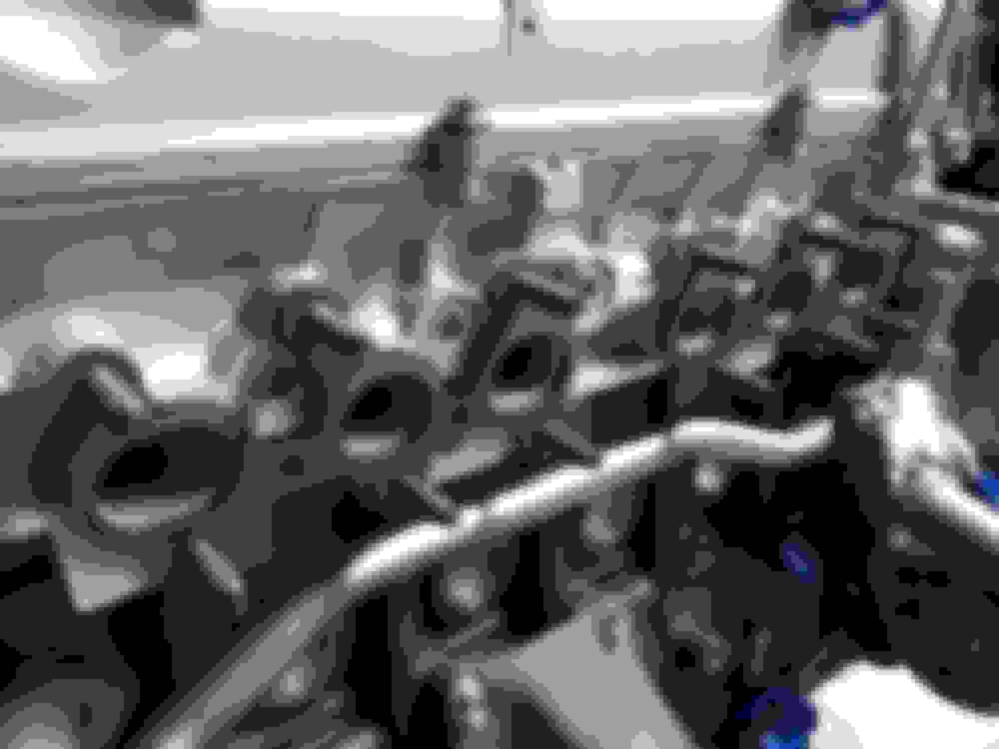
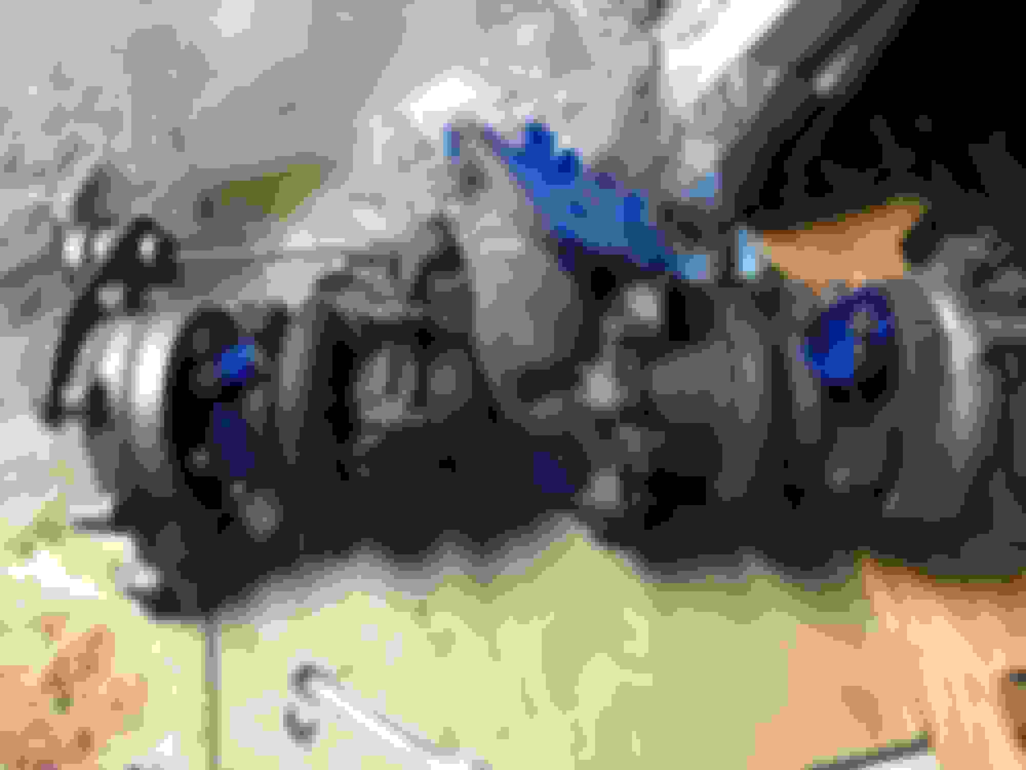
The first two connections go from the EVAP VSV on the TT pressure tank to the two metal vacuum line connections on the big intake manifold stay which also functions as a huge brace.
To the right of the image you can barely see where two vacuum hoses go to the EVAP VSV. Then you can see that from the "stay" one of those connections has a hose going upward-- this goes to where a built-in vacuum port is located on the intake plenum (this is NOT meant to be connected to the screw-in vacuum port adapter next to it). The next line coming from the big "stay" has a hose going into the smaller "stay" located to the left of it.
Next, the hose coming from the smaller "stay" goes up to a larger black painted metal pipe assembly that bolts to the upper outside of the GTE intake plenum.
This black painted piping eventually leads out to a hose that runs along the rear of the engine and connects to the GTE charcoal canister on the passenger side rear of the engine bay.
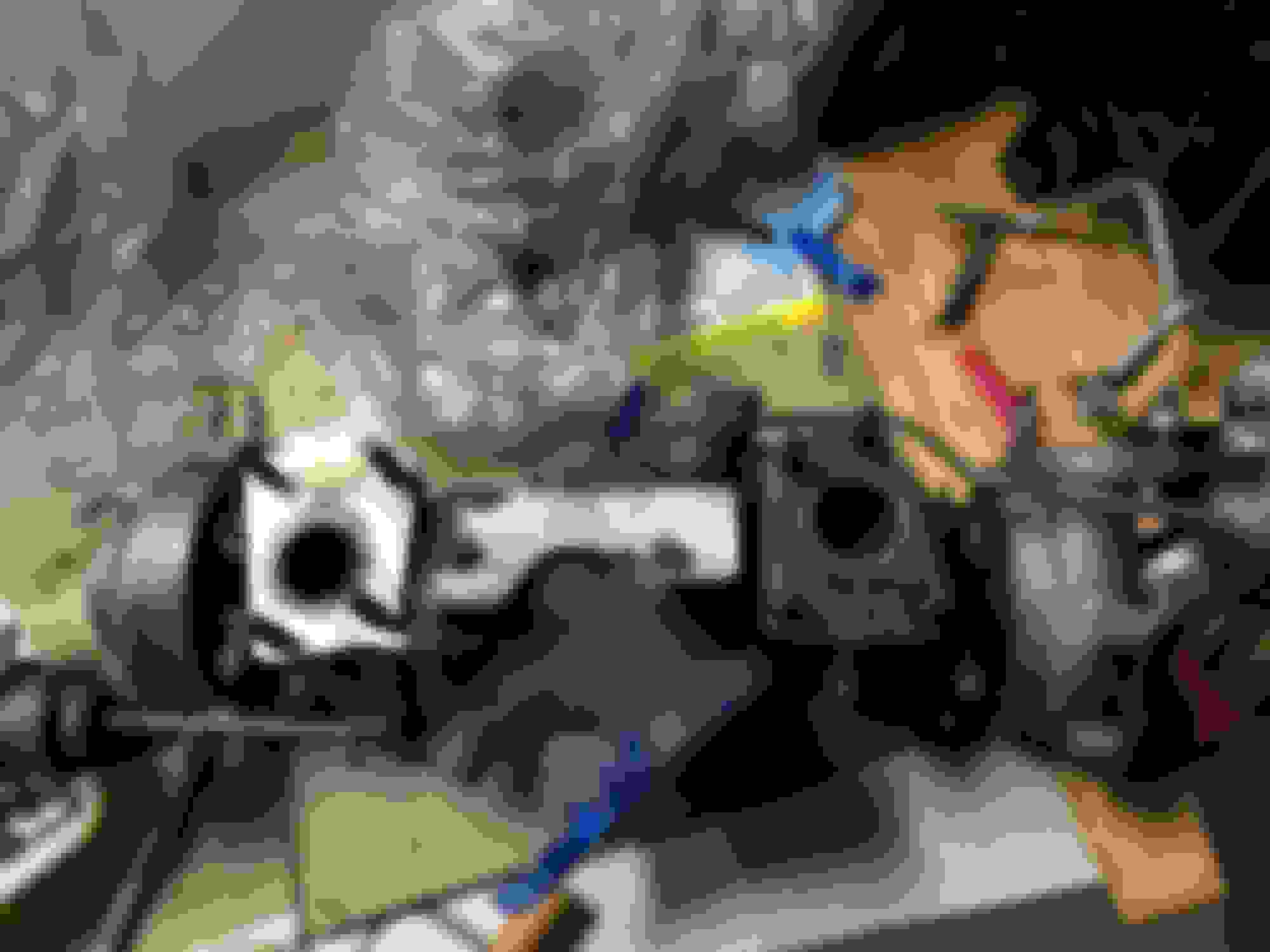
But before that a small "T" section of the black metal pipe uses a small hose that connects to a check valve and then a very small hose after that to connect to the rear of the GTE throttle body (barely visible but you can see the small vacuum port at the very rear of the throttle body in this picture below).
That check valve and its pictured orientation is REQUIRED for the system to work correctly. It limits the EVAP system from getting full boost vacuum pressure which would hinder its operation.
2JZ-GTE Fuel Pressure Regulator (FPR) and FPR VSV hose routing
Two hoses (90447-08091) are used for both connections. They have some wound plastic bendable flex protectors on them.
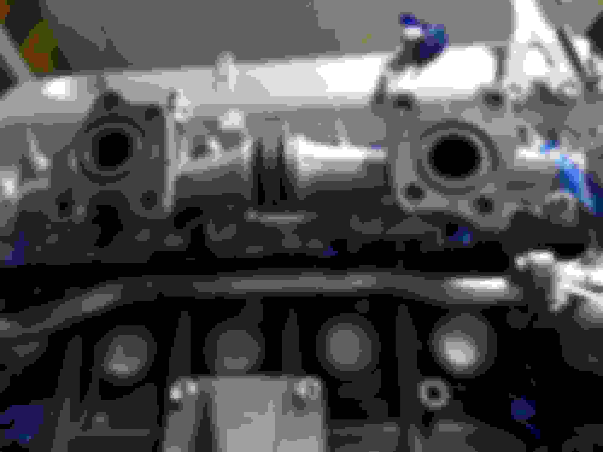
One hose connects the nipple on the FPR to the bottom of the FPR VSV. The other hose connects to a "Y" shaped vacuum splitter (90413-05002) which also connects to the MAP sensor and the intake plenum screw-in vacuum port adapter in the manner shown below in the third picture.
Above you can also see the built-in vacuum port next to the screw-in vacuum port adapter (very left edge of the picture). A hose is coming down from that port which leads to the EVAP system (out of the image frame).
Don't confuse those two vacuum source connections: The built-in vac port is used for the evaporative emissions system. The screw-in vacuum port (the black round thing shown above) is what is used for the MAP sensor and fuel pressure regulator system.
I thought you were going to try the cardboard box with foil for a makeshift oven? I'm still curious how well it works.
I did want to try making one but ultimately I ran out of time and had to rush the assembly of the turbo side right up to when I had to leave town. That was a good call because not only did I figure out several parts and hoses that I was still missing but if I hadn't buttoned up the engine and binned all the remaining parts I am not sure how things would have gone if things had been worse through the recent hurricane (Irma).
The instructions from VHT do say that the paint can be bedded in with the parts on the engine as it reaches operating temperature. It just requires several cycles of heating and cooling. I figured I would have to take my chances during the first startup and break-in cycles for the engine.
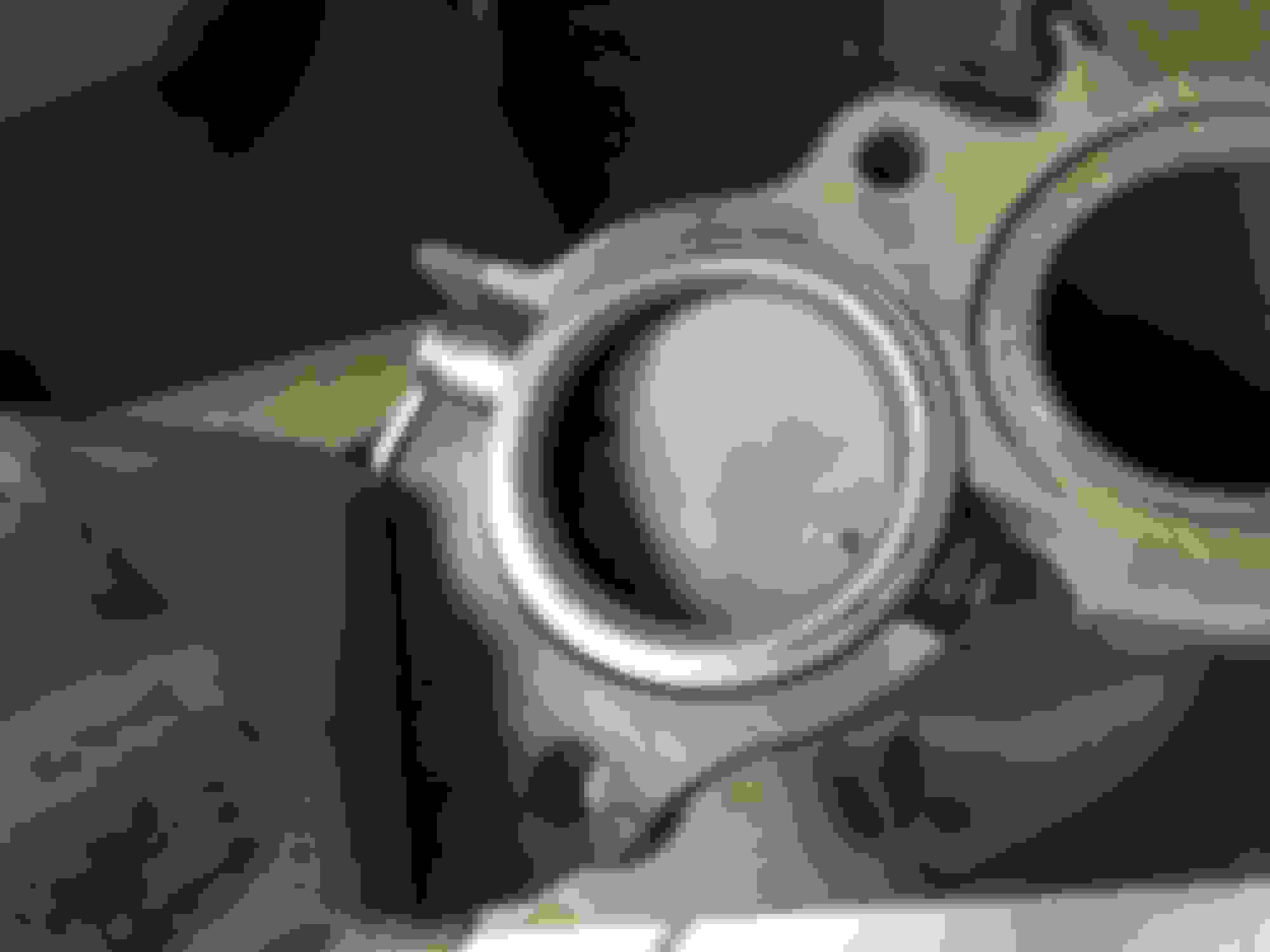
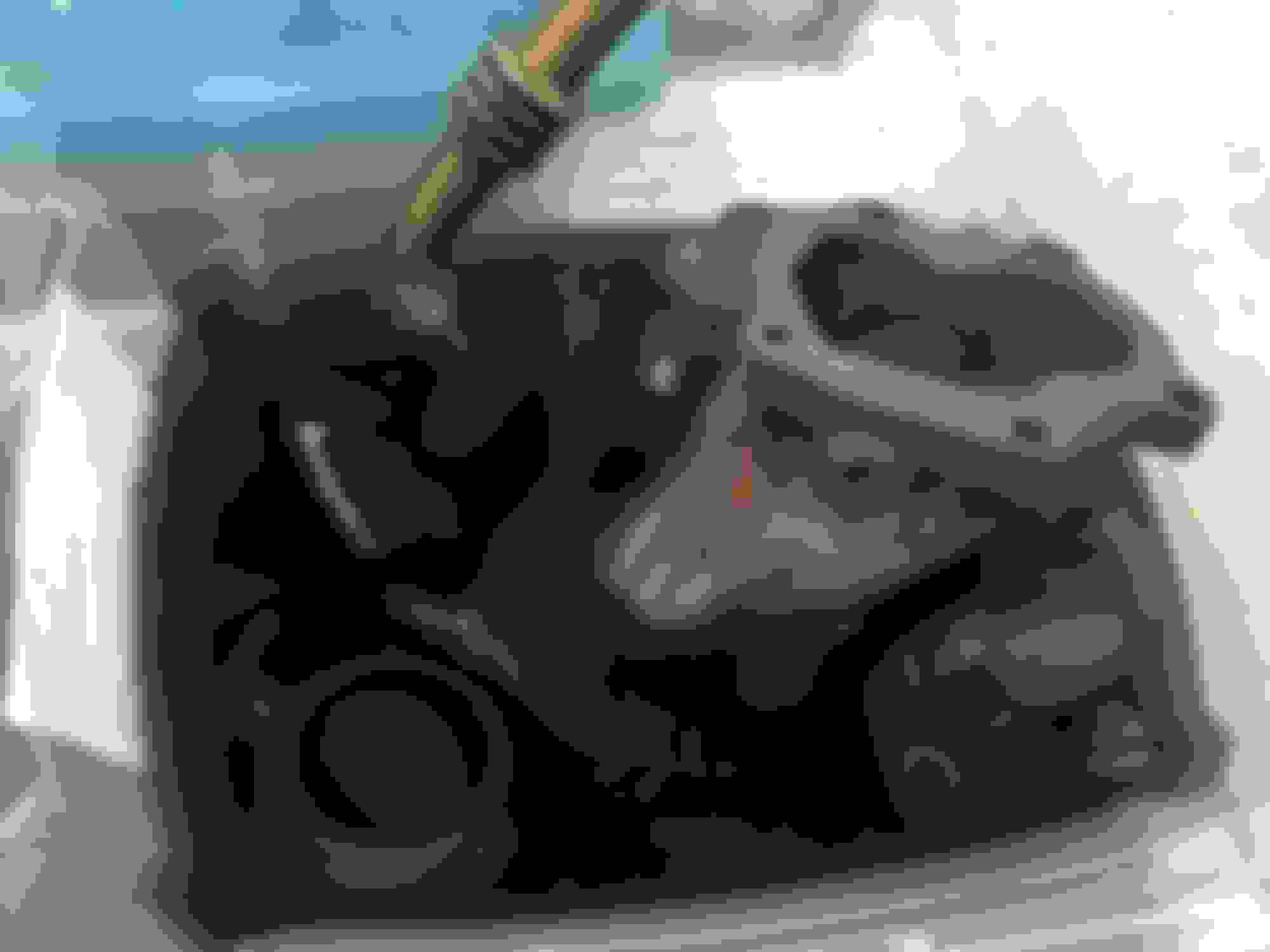
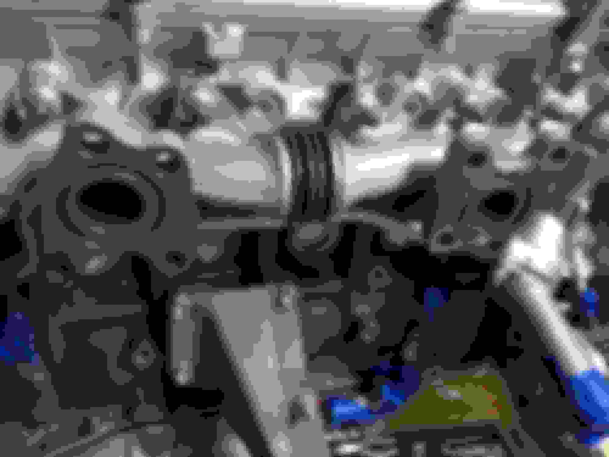
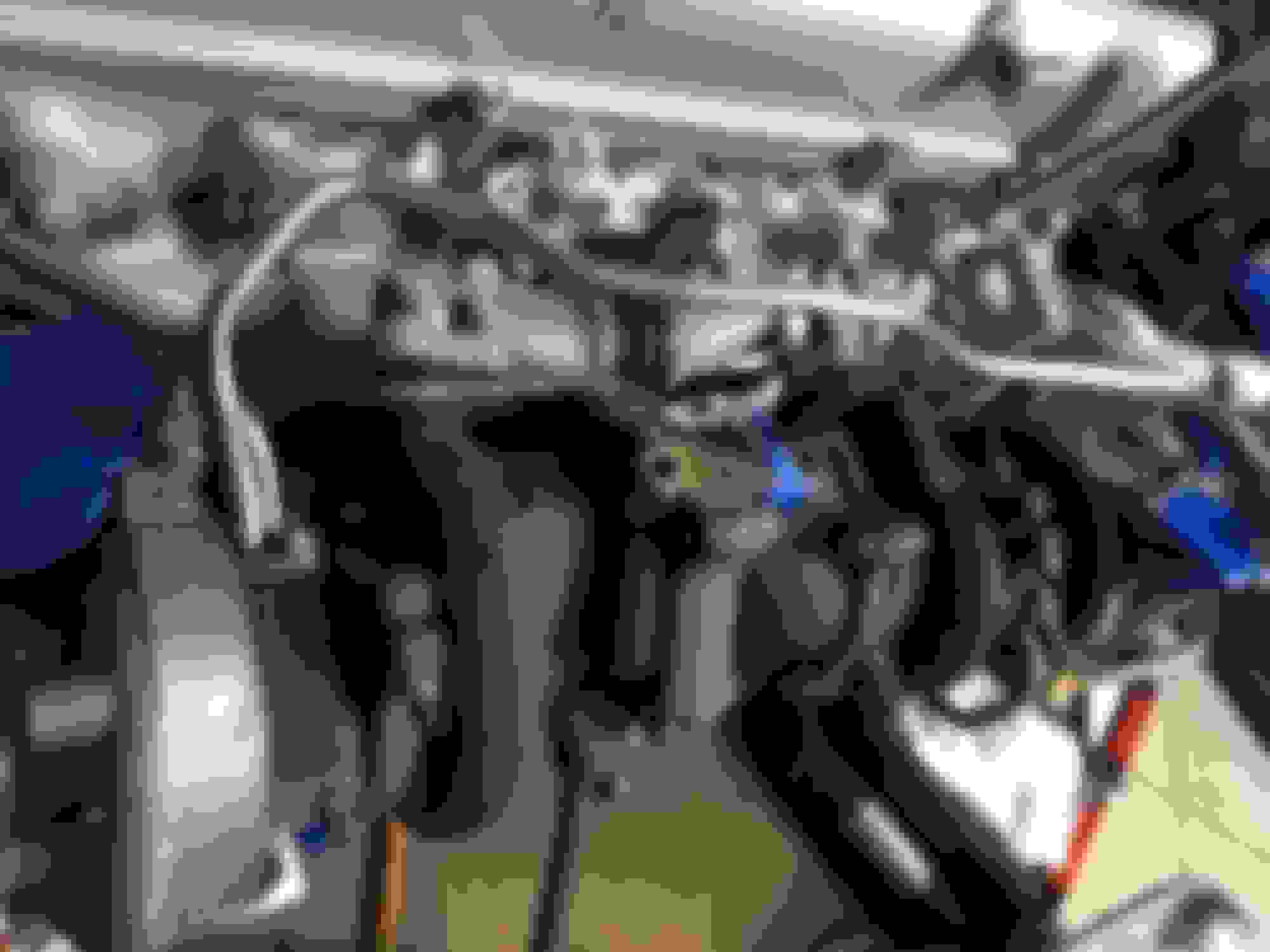
USDM 2JZ-GTE stock twin turbo #1 and #2 assembly to Y-collector
This was just a little tricky to do by the book due to the clearances available for some of these nuts. What ended up being necessary was using a small crows-foot type socket (which is not really a socket so much as a wrench end that bolts to a ratchet or torque wrench). I believe it was a 12mm or 14mm crows-foot that was required. The studs themselves went in with a small 6mm wrench if I am not mistaken. Not just any 6mm socket would fit correctly. I bought a tiny Craftsman 6mm wrench for that and it fit snugly on the stud to get them all the way in.
Some part numbers for the studs (I was able to re-use all my stud nuts so I didn't buy any of those): —90116-10175 — x2 stud for turbo #2 to Y-manifold (reverse stud) —90126-08009 — x6 main stud for turbo #1 and #2 to Y-manifold (actually 10?)
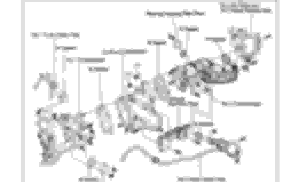
Assembly is the reverse order of the removal instructions in the MKIV TSRM EG-150 "TURBOCHARGER SYSTEM"
For this I used a Toyota all-in-one turbocharger side gasket kit for the USDM GTE engine:
As mentioned before, the turbos I used had racked up 150k miles and were run up to 18psi max with no issues or smoking so said the seller (whom I met and whose Supra I was able to see in person). At this point they have been sitting for about four years. I would have liked to have had them rebuilt at the time but for just over $1k I would trust that they have some life left in them at stock boost.
There is always the second set with 40k miles that I bought from Gerrb. If I must I can throw those on. One set or the other will be rebuilt and fitted onto the car. More than likely I will need to learn how to remove and replace a set of stock twins with the engine in the car at least once.
Just as with the exhaust manifold going onto the cylinder head, all these stud nuts have to be torqued in a specific order in several passes. For this a 14mm crows-foot was necessary to clear many of the obstructions in the way. Torque for these nuts is 40 ft-lbs each.
The studs that bolt the turbo assembly to the exhaust manifold already on the engine block are P/N 90116-10175 (x8). The nuts are 90179-10167.
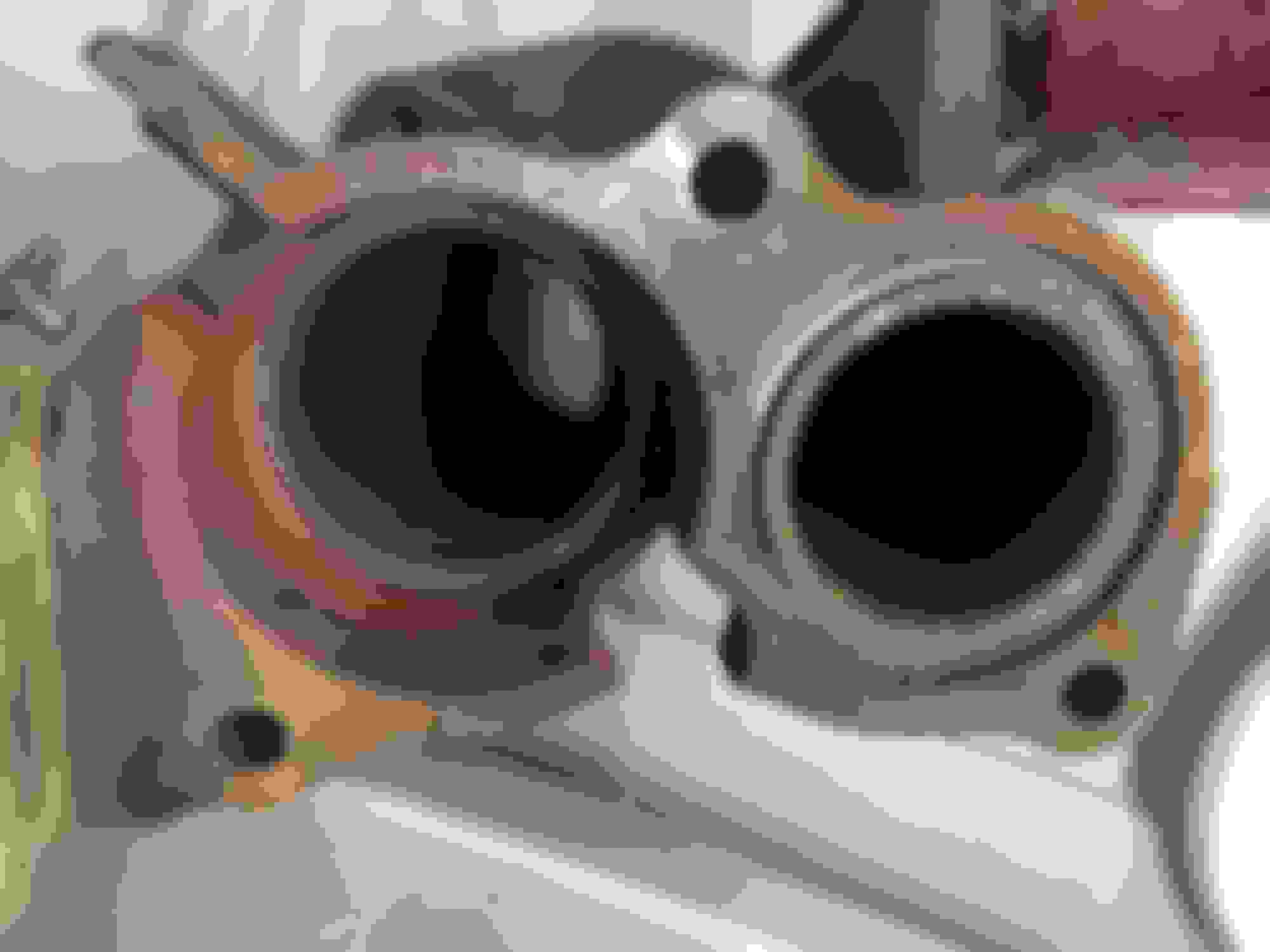
Two (2) ring shaped gaskets (17278-46011) are used to go in the circular areas in the exhaust manifold. The turbochargers both clamp down over this. There are no additional flat gaskets in the shape of the manifold. It's just these circular gaskets. To me they appeared to be made of a ceramic material.
Those gaskets are also included in the USDM TT turbocharger gasket kit I mentioned previously.
After doing that there are two large turbo "stay" braces that get bolted on with two (2) bolts (90080-11361). Those get 32 ft-lbs of torque each.
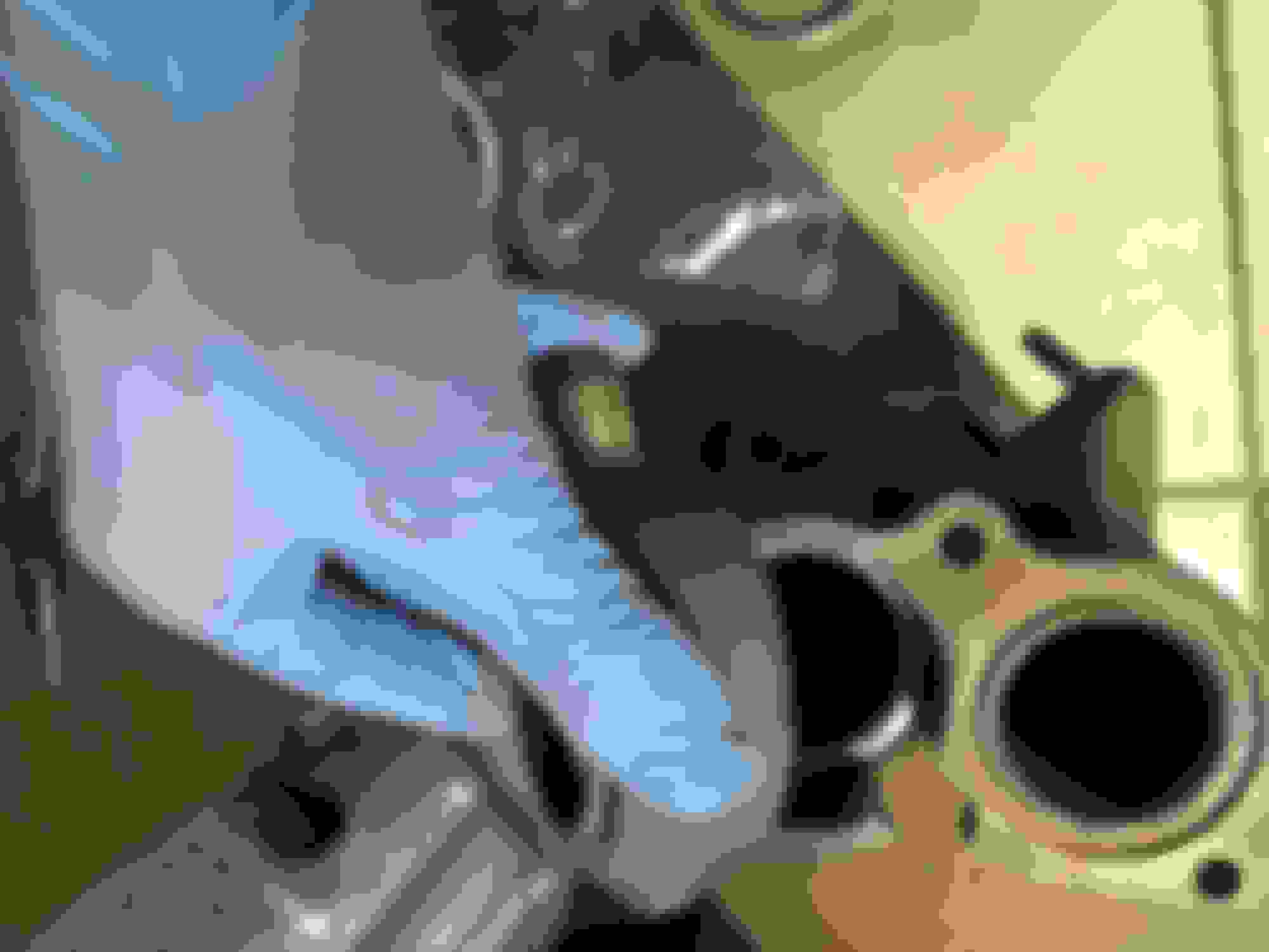
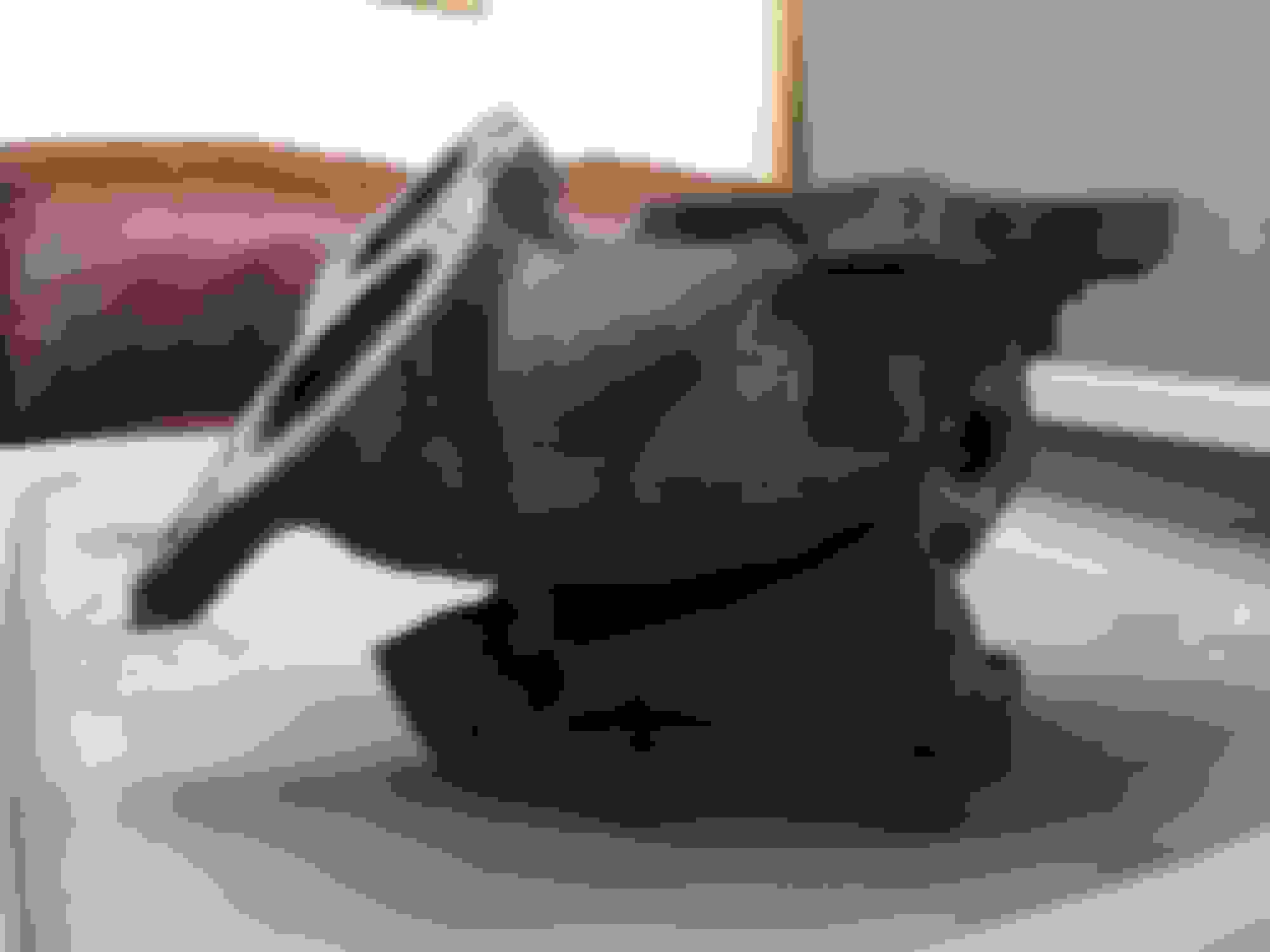
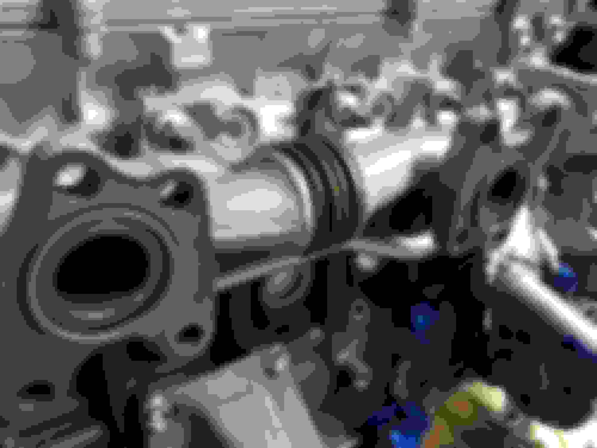
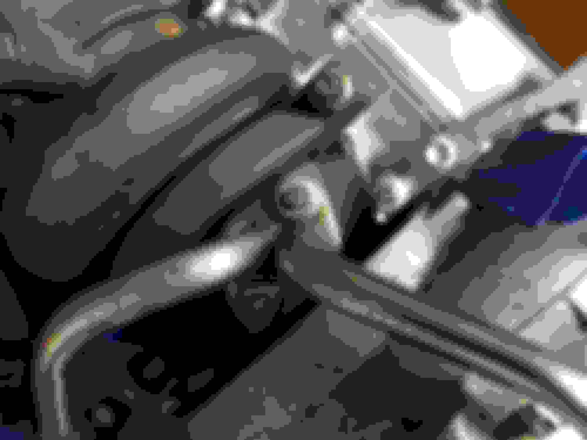
Turbo #2 water cooling hard lines
Then the water cooling lines for turbo #2 get bolted on with a new gaskets. This proved to be a PITA later as it was obvious it was taken off in the incorrect sequence which left other parts in the way. This hard line was so bent out of shape I had to carefully muscle it back how it needed to be to clear everything but also line up exactly where it should be for mounting bolts and hose connections. I wore my arms out doing that for a couple of hours.
The water cooling pipe gets 78 inch-lbs of torque.
^^ It's on there but it's VERY bent out of its proper shape. To be corrected in later photos.
I did want to try making one but ultimately I ran out of time and had to rush the assembly of the turbo side right up to when I had to leave town. That was a good call because not only did I figure out several parts and hoses that I was still missing but if I hadn't buttoned up the engine and binned all the remaining parts I am not sure how things would have gone if things had been worse through the recent hurricane (Irma).
The instructions from VHT do say that the paint can be bedded in with the parts on the engine as it reaches operating temperature. It just requires several cycles of heating and cooling. I figured I would have to take my chances during the first startup and break-in cycles for the engine.
That's understandable. I was looking at the process for the flame proof paint recently, and it's a lot of work. I don't think the cardboard box would have been safe up to 650 degrees.
^^ I never got that far with planning the disposable oven but beyond 400 degrees I agree with you. I'm pretty sure things wouldn't be safe beyond that temperature if using cardboard.
I've been checking your thread every now and again. I must say exceptional progress.=)
Really can appreciate all your attention to detail and taking your time with your goals. Hope you get the SC exactly where you want it to be within your intended timelines!
I've been checking your thread every now and again. I must say exceptional progress.=)
Really can appreciate all your attention to detail and taking your time with your goals. Hope you get the SC exactly where you want it to be within your intended timelines!
Thank you!! I also do hope I can get it there within a good timeframe! It's inching forward
As for this thread it is almost caught up to the present. Just a few more sections left to cover the assembly so far.
The car is purring along with the original engine and I am still grabbing parts here and there. Now I'm down to tune-up parts such as new ignition coils, a new igniter, O2 sensors, etc. and a new stronger single-disc R154 clutch kit that's rated for much more than 315+ ft lbs with a good lifespan.
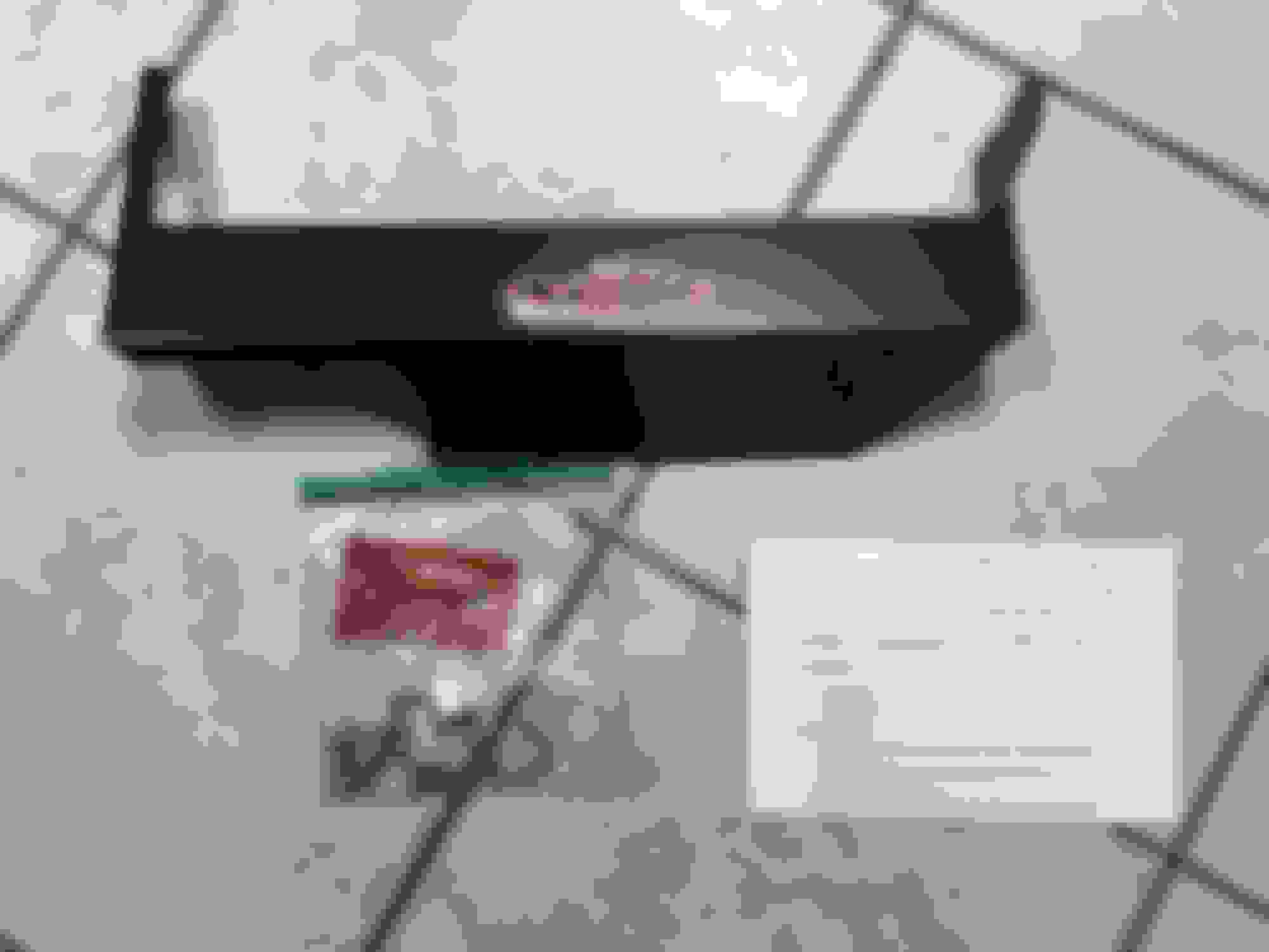
Momentary thread detour to the present: MKIV Supra passenger seat H3R fire extinguisher bracket install
A couple of months back I stumbled on a thread on SF where a member was selling custom made steel H3R fire extinguisher brackets for stock Supra MKIV passenger seats. Since I have a set of those in my SC and I have considered mounting a small fire extinguisher somewhere in the front of the car this appeared as a great solution. I bought one and had it sitting around for a while. I kept noticing it but didn't want to install it until I had the H3R quick release mounting bracket (P/N #NB300) and the extinguisher itself.
Last night I got annoyed with it and decided to install it without those parts. I can deal with them later.
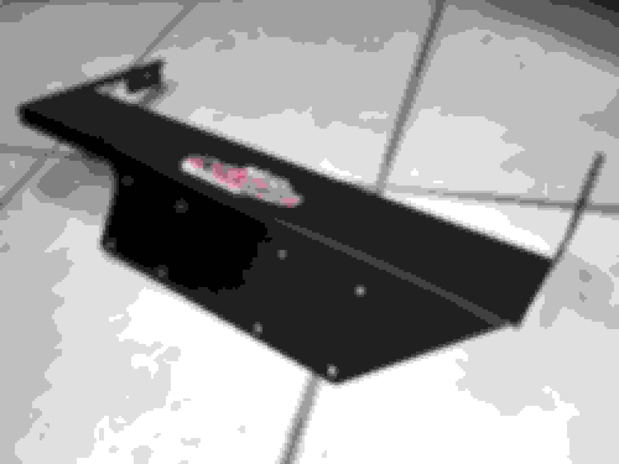
It was surprisingly easy. The kit comes with instructions and all the screws and nuts required. The large kit nuts are 11mm size and the large kit bolts are a 3/8ths socket size (not 10mm as you might be inclined to try). On one side an additional mounting hole has to be drilled with a cobalt or better 1/4" bit. On the other side I found I had to slightly bore out one of the existing holes in the MKIV seat mounting frame with the same 1/4" bit.
Overall it's very well made to the level of a dealer installed OEM accessory bracket. Without the quick release hardware and extinguisher you hardly know it's under the seat. It fits and clears perfectly with an SC's floorboards. Forward and back adjustment of the seat are not affected and at least without the rest of the hardware mounted it's tucked well under the cushion lip. The tucked away design is supposed keep the small extinguisher from hitting under the knees and calves of passengers while leaving the pull tab and bottle within easy reach of the driver.
Now maybe this is overkill for a stock GTE engine swap but I don't feel like chancing anything. I'll add to this a set of fire-proof gloves somewhere handy in the back seat.
FYI, the seat bolts to the body of the SC (or MKIV) require 27 ft-lbs of torque according to the TSRM.
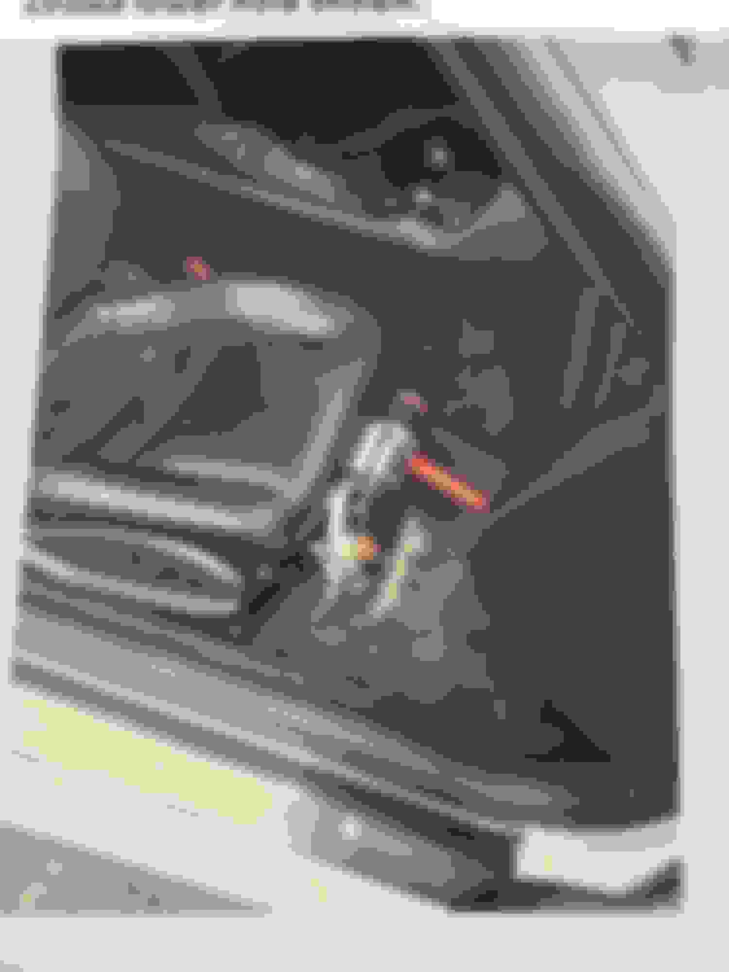
A finished example picture of this bracket with extinguisher mounted in an MKIV (from the original SF thread):
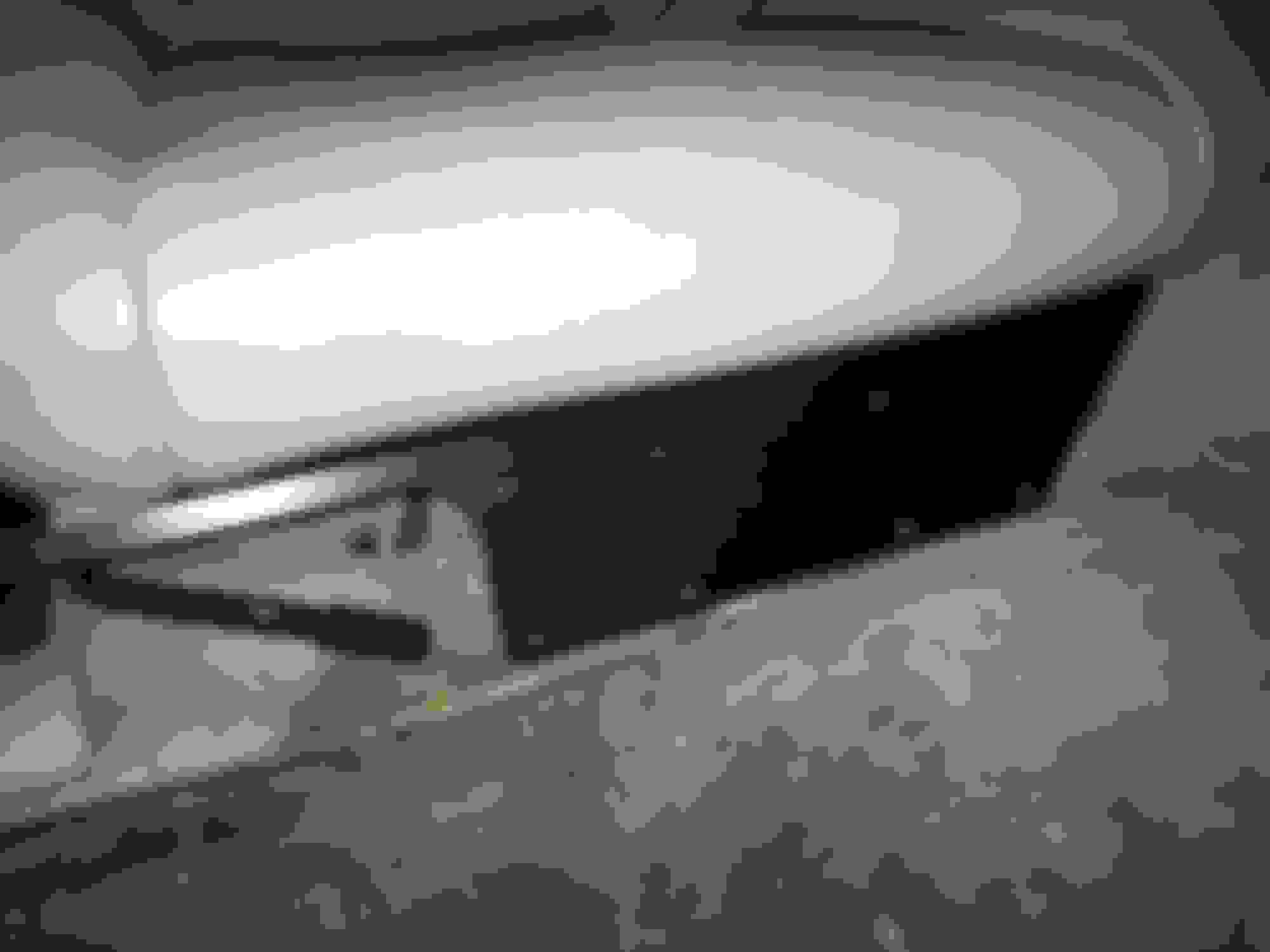
And how it's finished in my car as of last night. Please forgive the dirty carpet and old floor mats. Those are due to be addressed but I just haven't gotten to them yet. The front floor mats are beyond saving and just need to be replaced
Today I picked up a much belated finishing touch for the front suspension: a front swaybar from a 1994 Supra MKIV TT. It also will allow me to fit in the stock TT intercooler pipe that goes just under the radiator.
I need some new bushings and end links for it but I can't wait to see how this improves the front end handling.
 09-30-17, 05:30 PM