When you click on links to various merchants on this site and make a purchase, this can result in this site earning a commission. Affiliate programs and affiliations include, but are not limited to, the eBay Partner Network.
As promised in my project thread, I'll spend an hour or two compiling the best timing belt and water pump DIY that I can from my experiences doing a few on this generation. I hope this helps some folks out as it takes quite a lot of work to put something together like this. I would rather do another timing belt than make an extensive DIY like this any day!
Here we go.
This isn't a job to pop your mechanicin' cherry on. You need to somewhat know how to swing a wrench. But really this job is about two things: Being organized and following directions. I'll try to highlight the do's and dont's to keep you out of trouble. If you can do that you're 80% there. Keep your parts organized and take it slow. Some swear by the baggie method for parts organization but I've been turning wrenches since I could drive and don't feel the need to do that unless I'm leaving a project apart for a long period of time. I either put the nuts and bolts back where they were after removing a component or set the fasteners with the part that as removed. That works well with this job.
The tools: Most every fastener on a Toyota is a 10, 12, 14, or 17. That will get most everything you need done except for a few larger and different style fasteners. Go after those sizes for eyeballing what socket or wrench you need.
1/4" metric socket set with ratchet
3/8" metric socket set with ratchet and various length extensions
1/2" metric socket set with a long ratchet
1/2" drive 22mm 6 point socket for crankshaft pulley bolt
8mm hex bit socket for timing belt tensioner pulley bolt
I highly recommend the Schley crankshaft holding tool but you may be able to do the job without it
Metric combination wrench set (preferably ratcheting wrenches)
1/4", 3/8" & 1/2" torque wrenches to cover a few dozen in-lb's to 181 ft-lb. You can get away with the Harbor Freight torque wrenches but you better be familiar with using a cheaper clicker torque wrench as you can easily over torque and break or strip a fastener if you miss the faint click at lower torques. A beam 3/8" torque wrench is an accurate easier to use tool than clickers. That will get you by except for the crankshaft bolt at 181 ft-lb.
Assorted pliers for hose clamps and such
Screwdriver set
Pry bars may come in handy
A nice dead blow hammer makes some things in this job very easy. Again, a cheaper dead blow is available at Harbor Freight but don't expect it to take much abuse
Fluid drain pan for draining coolant
Ramps or floor jack and jack stands preferably
One foot length or so of 3/8" ID hose for directing coolant when draining
Patience
The parts:
Aisin timing belt and water pump kit ($175 from RockAuto) Don't go cheap here folks. The Aisin kit includes all OE parts. It's the only way I recommend going with this.
2 gallons of Toyota Long-Life Coolant that is red in color.
Toyota FIPG. Use the right stuff people. This is the right stuff. This will be used on the thermostat housing to water pump flange. It's used all over these cars, very handy to keep around. p/n 00295-00103
Cam seals if yours are leaking. 90311-38036
Crank seal if yours is leaking. 90311-A0001
Blue loc-tite (thread locker)
Patience
Let's quickly go over my method which almost mirrors the shop manuals method. But first put the car on ramps or jack stands. Jack stands may be easier as you can get it a little higher. A good lift point is the aluminum engine cross member, but place a piece of wood between the jack pad and crossmember to avoid damaging the cross member. You can set jack stands under the cross member but be very careful where you place them. It may be a little safer to place them under what looks like a frame rail of the unibody. Just outside of the head shields around the exhaust is a pretty solid section of the body that looks like a frame rail or sorts. You can place the jack stands right under the lower control arm bushings but I feel that puts an awful lot of stress on the LCA bushings since they are not meant to hold the cars' weight in that direction. Either way you go be sure to engage the parking brake.
Now let's talk about the most important part of mine and Lexus's method in my opinion. After setting the crankshaft at TDC via the crank pulley markings, you will then turn the crankshaft approximately 50 degrees in the normal direction of rotation (CW). This lowers all of the pistons in the bores allowing you to turn the cams all you want without any piston to valve contact. You will also be able to line up the cam and crank marks on the new timing belt with the crankshaft in this position. You will only move the crankshaft back to TDC with the new belt to check the timing marks one last time. Most all other DIY's I've seen say to leave the crankshaft at TDC for the whole job. Don't do it that way guys! With the crankshaft 50 degrees ATDC the cams usually don't slam over like they do at TDC after the belt is removed.
Loosen coolant bottle cap. Place a drain pan under your radiator drain that is located on the passenger side bottom of the radiator. Use pliers if needed to open the drain. You can place a 3/8" ID hose on the drain to direct it into the pan but coolant usually leaks from the drain valve as well so a large drain pan sitting under it will catch the stuff the runs down some of the body parts under there. After that is empty go ahead and remove your lower hose connection at the radiator. You will get more coolant this way so don't assume it's empty. Leave the drain pan under the radiator for this reason.
After the radiator is empty and disconnected at the lower hose, it's best to drain the engine block drains at this time as you'll want to put fresh coolant in the car after this as it's most likely old and may even be the wrong stuff. The drains are on each side of the engine block accessed with a long 3/8" extension with a 10mm socket. You may want to use a u-joint to improve the angle of the socket not the drain. The extension is placed up between the steering rack and engine cross member to access the drains. Before opening place a short length of 3/8" ID tubing over the drain nipples to help guide the coolant into your drain pan.
After you have all of the coolant drained, pour your waste coolant into containers and dispose properly. You need the drain pan for the next step.
While you're under there, remove the 2 transmission cooler hoses from the radiator.
Some transmission fluid will pour from these hoses and the radiator when removed so make sure the drain pan is under the radiator. It won't be much.
Unplug the radiator fan coolant temperature sensor on the lower drivers side of the radiator.
There is a small tab you push in with your finger while pulling. Don't go crazy on connectors as they are 20 years old and the ones near the engine like to break very easily. Don't go prying it off with a screwdriver. They come off easy when the tab is pushed in enough. This is what you're looking at when removing the lower rad hose connection, trans cooler hoses, and disconnecting the radiator fan coolant temp sensor.
Since you're still laying down there, remove the 2 lower fan shroud bolts.
Remove the 2 nuts and 1 bolt on the engine appearance cover.
Remove the cover and set aside. This is where I will start setting fasteners with their parts. I lay the cover upside down and lay the 3 fasteners in one of the cubby's built into the cover. Untouched other than appearance cover and air cleaner inlet removed
Disconnect the battery cables.
This should really go without saying when doing any sort of disassembly of the engine but I figured I would say it anyways.
Remove air cleaner inlet that goes across the top of the radiator.
There is one 10mm bolt near the battery then the assembly just lifts off the air cleaner box.
Unclip and unplug MAF sensor connector.
If your car still has the MAF wiring properly clipped just insert a flat head screwdriver in the slot and pop it open. I'm talking about the clip on the wiring, NOT the connector. The connector is usually broken if it's been messed with but is supposed to have a tab to push down while pulling.
Remove air cleaner assembly from plastic intake connector.
Unclip the large clamp that holds the air cleaner assembly together. Remove the 3 10mm bolts holding the air cleaner assembly to the body. Loosen the 10mm headed hose clamp closest to the engine. Remove the engine assembly, clamp it back together, and place the 3 bolts back in the holes from which they came for safe keeping,
Remove air intake connector from throttle body.
Loosen the 10mm hose clamp holding the intake connector to the throttle body. Remove the 10mm bolt holding the intake connector to the valve cover just aft of the throttle body. Slide the 3 constant tension spring clamps a few inches down the hoses. Carefully remove the 2 small vacuum and 1 large air hose from the intake connector. The large hose is metal reinforced, the smaller ones are not and will break if you're not careful. The 2 small hoses come off fairly easy, sometimes they split, but the larger hose is easier disconnected while pulling the intake connector away from the throttle body.
Remove drive belt.
With a 14mm socket and a somewhat long ratchet on the tensioner pulley bolt remove tension from the drive belt, slip it off the pulleys and remove the drive belt. Drive belt tensioner bolt
Remove 4 nuts holding the fan fluid coupler to the fan bracket pulley
This part sometimes sucks. You can try loosening the nuts prior to remove the drive belt, but usually they are too tight and the fan bracket pulley just slips. I usually just hold a large flat head screwdriver between the fluid coupler shaft and one of the other nuts to hold it while loosening the nuts. This is one place where ratcheting wrenches will save you tons of time. Large flathead holding on the right and ratcheting wrench not the left.
Remove the 2 upper fan shroud bolts.
Now remove fan assembly together with the fan shroud from the fan bracket pulley.
The center of the fluid coupler shaft and fan bracket pulley is somewhat of a press fit and is usually on there pretty good. I usually take care and lots of patience to slowly pry it off. You don't want to go crazy here as you could break fins on the fluid coupler or bend the shaft. Two bend tipped pry bars are sometimes nice here so you can work it back and forth. Store the fan and fluid coupler assembly with the fan down. I'm not sure about this one but most manufacturers require you to NOT store it with the fan up as the fluid can leak out and she'll be toast after that. So just store it fan down and shaft up. Pry bar against fan bracket pulley stud and fluid coupler. Be careful here and go easy!
Temporarily remove the 2 10mm bolts holding the overflow hose to the body. Loosen the spring clamp. Remove this hose from the top of the radiator. Remove the upper hose from the engine and radiator. Remove the 2 12mm nuts holding the radiator mounts to the body. Pull the radiator up taking care not to damage the fins. Place to the side with the front down so you don't drip coolant and ATF all over the place while it is sitting. With the radiator out, reinstall the 2 bolts pictured for organization purposes.
Here is how it should look with the radiator, fan, and fan shroud removed.
Remove the upper hose and thermostat housing assembly
Remove the 2 nuts and the upper house and thermostat housing assembly. As usual, reinstall the 2 nuts for organizational purposes.
Remove both upper timing belt covers.
There are 4 10mm bolts on each side. Set these aside upside down with the bolts laying in them. There are rubber gaskets surrounding them. Make sure you don't lose those. It's common for the small rear gasket to fall off and sometimes go missing so keep track of the seals if you can. The are reusable. Drivers side
Passengers side
Remove bank 2 ignition coil/bracket and unplug bank 2 camshaft position sensor.
The bank 2 camshaft position sensor connector is clipped to the bottom of the bank 2 coil bracket. You can remove the high tension cable from the back of the coil, remove the 4 phillips screws, and get a small pick at that connector to release it from the coil bracket. Usually if these have been messed with by someone who doesn't know what they are doing they are already broken. The coil connector itself is usually alway's broken already or breaks when you try to remove it. It's subjected to a lot of heat there and get's brittle. I alway's replace these with new connector's from Toyota when this happens. The 2 10mm fasteners holding the coil bracket to the engine.Here is what it looks like behind the coil for you to see what you're dealing with here.
Remove drive belt idler pulley
Set aside with the bolt for organization.
Disconnect Bank 1 camshaft position sensor connector
Unclip and unbolt wiring from the front of the engine. Disconnect the connector. This connector usually breaks too and I usually replace it but I've never seen one pull apart if you don't. You can also go ahead and pop the round grommet out of the timing cover and set it aside somewhere. It's a split circle type deal.
The alternator needs to be somewhat set aside to be able to remove the drive belt tensioner. You do not have to disconnect the alternator wiring on the back. Just remove the 14mm nut and 12mm (I think) long bolt, slide the alternator off the post and set it aside. Place the nut back on the stud for now for safe keeping. The long bolt can just set in the alternator.
Loosen AC compressor from the engine.
The compressor also need to be set aside in order to remove the fan bracket. As with the alternator, nothing needs to be disconnected from the compressor itself. There are 3 bolts holding the compressor to the engine Two in the front and one in the rear. First remove the bolt and nut where the ground wire attaches to the compressor. Then remove the 3 10mm bolts holding the drivers side louvered plastic splash shield to the body. This will allow you to get your long 3/8" drive extension and 12mm (?) socket to the rear bolt to remove it. The front two are easier but you need to pinch the tabs on the wiring retainer that is blocking the upper bolt in order not to damage that. There is a bent metal 'hook' that aids in compressor installation that hooks around the fan bracket and holds the compressor up. Remove these two fasteners and let the cable hang.
Remove these 3 bolts and splash shield to improve access for the rear compressor bolt.
Here is a view of the extension sitting on the rear bolt
Pinch these tabs with small pliers and push the clip through the hole to improve access for the top bolt
Here is the ratchet sitting on the top bolt
This is the bent metal 'hook' that hangs on the fan bracket to aid in installation
Remove Bank 1 ignition coil and bracket assembly.
With the compressor set aside the bank 1 ignition coil and bracket is easier remove. There is a bolt at the front of the cylinder head and a smaller one going into the fan bracket holding the coil bracket to the engine. With the compressor removed the bolt on the cylinder head is easier to access. A ratcheting wrench helps with the bolt in the head as well. You'll obviously need to remove the bank 1 coil high tension cable as well as the same type of black coil connector as the bank 2 coil has. These parts are usually pretty oily from valve cover oil leaks. This is the bank 1 ignition coil and bracket assembly looking at the back of it so you can see what you're dealing with.The phillips screws never need to be removed unlike the bank 2 coil and bracket assembly.
This thing is a freakin pain... I never totally remove it as it seems like it would be tough to do without at loosening the power steering pump and setting it aside. You can get around it if you're careful. You'll need to remove a bolt on the front of the cylinder head and a 10mm bolt on the front of the RH timing cover to loosen it. You'll also need to disconnect it from the coolant tank and the thermostat housing. There is also a clip holding a wire loom to the outlet hose assembly that is better if unclipped. A stubby flathead usually helps here. With the outlet hose assembly loosened and remove from the thermostat housing just let is dangle there so you can fight around it later, without bending it of course...
Remove RH timing belt cover
Remove the 4 10mm bolts holding the cover to the engine. Ensure the cam position sensor wire is out of it's clip on the timing cover. Pull the wiring loom plastic push pin holder from the hole in the top of the timing belt cover. Pull the timing cover forward off the posts and wiggle it around the stupid reservoir outlet hose assembly. A little square rubber grommet will stay on the cam position sensor wiring.
Remove LH timing belt cover
Remove the 3 10mm bolts holding the cover to the engine. Ensure all wiring is unclipped from the timing cover and that the bank 1 camshaft position sensor round grommet is removed already. Pull the timing cover forward off the posts and remove it from the vehicle.
Remove drive belt tensioner
Remove the 2 nuts, 1 bolt and remove tensioner. You can see how the fan bracket and drive belt tensioner all intertwine with the timing belt covers to cover everything up. Very cool engineering.
Remove both caps, rotors, and distributer housings from the engine
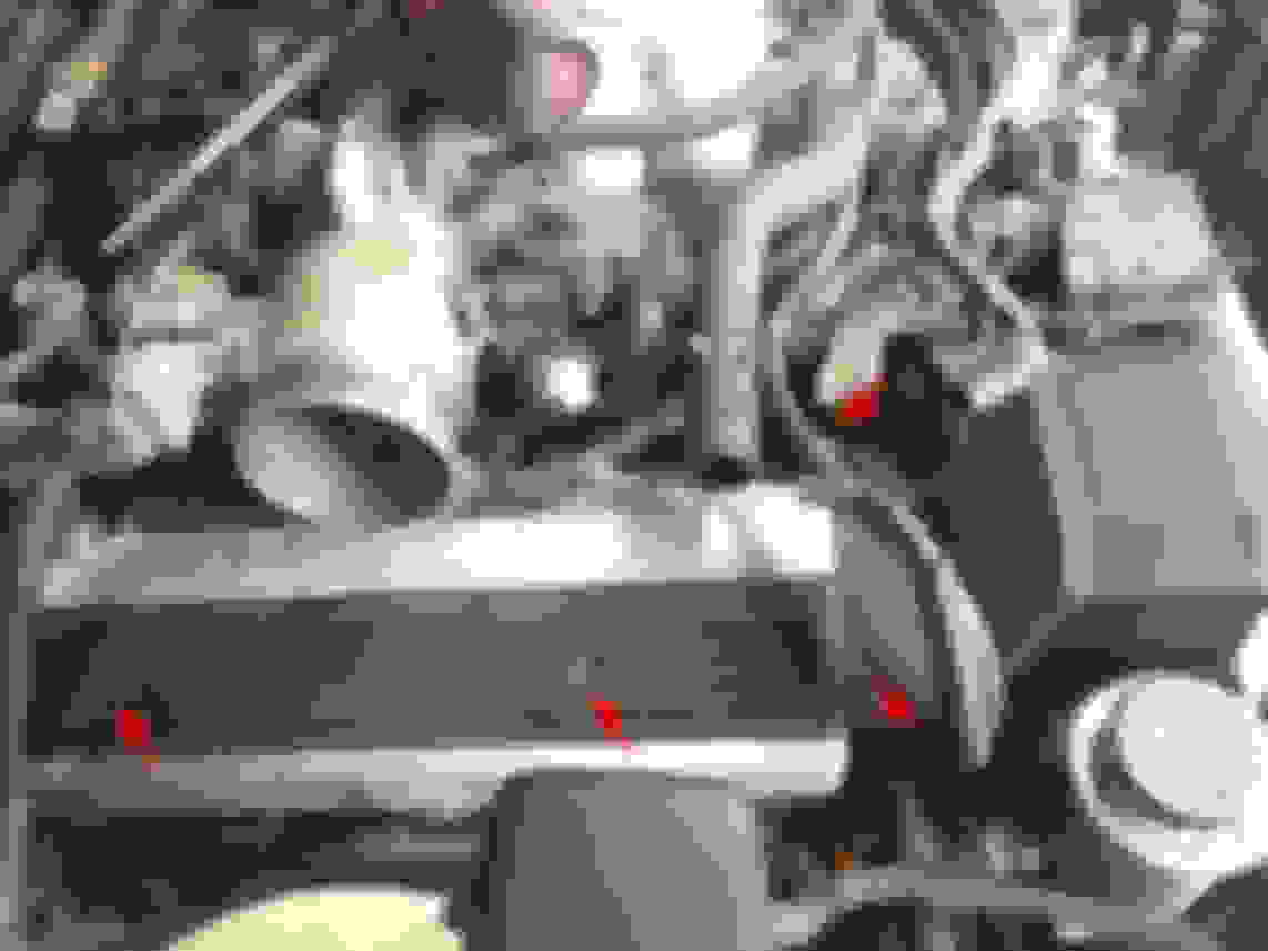
With an 8mm (?) or phillips screwdriver you can go ahead and remove the caps (which aren't L or R specific) and rotors (also not L or R specific.) The screws stay captive with the caps and rotors so don't worry about losing them. These are pretty cheap parts if you want to replace them (WITH OEM PARTS ONLY!!) Then remove the 2 bolts from each side holding the distributer housings to the engine. The distributer housings ARE side specific but are labeled L and R. Here the caps are removed after the 3 screws are loosened, the rotor screws are loosened with the rotor still in place, and the red pointers are showing the 2 bolts holding the distributer housings to the engine. Get it all off of there!
Remove the fan bracket
Remove the 2 nuts and 2 bolts holding the fan bracket to the engine. I like to leave the 2 bolts in the fan bracket for organization and put the 2 nuts back on the studs on the engine until removing the water pump later. Fan brackets are a common wear item on these cars are there is no better time than now to replace it. The are about $100 or so. Get the Aisin part from RockAuto. Don't bother with aftermarket. Aisin or Toyota PERIOD. Spin the pulley on the bench to determine if it is bad or not. I've honestly had pretty long life out of most of the ones I've messed with.
Get your long 1/2" ratchet and 22mm socket and put it on the crankshaft bolt. Turn the crankshaft until the line on the crank pulley lines up with the zero on the timing cover. Then look at the cam pulleys and see how the marks line up there. The notches in the cam pulleys will line up with pressed dents on the rear plates. If the notches on the cam pulley's are 180 degrees away from the rear plate marks, turn the crankshaft one more full turn. The #1 piston was at the top of the exhaust stroke, not the compressor stroke like we want. They are not marked from the factory but may be from a previous mechanic like this one is. This is just to familiarize yourself with how it should look when you are done, before you take it all apart. Crankshaft on zero.
RH cam lined up
LH cam lined up
(Optional) Loosen camshaft pulley bolts
If you want to check your cam seals or replace them you'll need to remove the camshaft pulleys. This is a good time to loosen the bolts. They are at 80 ft-lb if I remember correctly without looking. Put a long ratchet not the crankshaft bolt and use that to counter hold the camshaft pulley's while loosening the bolts. Do NOT remove the bolts completely of the pulleys will fly off in an explosive fashion. Just loosen them... You can also use a pulley counter hold tool to hold the pulley's if you have one. A lot of auto parts stores rent them for free. Don't go jamming something between the spokes and whatever is behind the pulley's as you will probably bend the timing rear plates and will have trouble getting the timing covers to line up when reassembling. If I didn't have the right tools I would probably reinstall the old timing belt components and use the belt again to counter hold the cam pulleys for torquing back on. I wouldn't want to use a brand new belt to counter hold pulleys with.
The camshaft pulley bolts torque back on to 80 ft-lb's
Loosen crankshaft pulley bolt
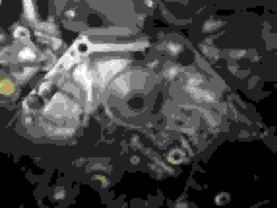
Here comes the fun part that everyone is afraid of. This bolt is ON there. I recommend using the proper tool to hold the crankshaft. It's a piece of cake that way. Your other options are using an impact to remove it wedge in the flywheel are to keep it from turning. Some people have also put a large breaker bar on the bolt and using the engine starter to loosen the bolt. I REALLY don't like that idea... I'm not a fan of impacting the bolt off either. I don't like sending that impacting action through the crankshaft and into all the bearings and such. On some Ford motors I've seen thrust bearings on the crankshaft shatter from impacting the crank bolts out. That is probably not the case on the 1UZ but I still don't like it. The proper tool is the ******. Once you get the crank bolt loosened we can move on to the next step. Here is the proper tool bolted to the crankshaft pulley. It has a 1/2" squad drive on it that allow you to counter hold it with a long ratchet or breaker bar.
This is my trusty 40" breaker bar with another breaker bar down below setting against something while holding the crankshaft. With a large enough lever you can move the world.
This was just for demonstration purposes something you may be able to do to lock the crank. I can't say I like this idea either but it's better than the breaker bar and starter deal.
Set crankshaft for disassembly
This is the important step I spoke of earlier. With the crankshaft bolt loosened, start out from TDC which is with all 3 timing marks lined up. Now turn the crankshaft in the direction of rotation (CW) until the white timing mark on the crank is lined up with the center of the timing belt idler pulley bolt head. This is roughly 50 degrees ATDC. At this position you can do whatever you want with the cams and you will not have piston to valve contact anywhere. The crankshaft bolt will somewhat tighten back up when doing this. I just put the ratchet in reverse and either give it a wack with the palm of my hand or with the dead blow and it should pop the bolt lose without moving the crankshaft back at all. In the end you want the bolt loose and the mark lined up with the center of the timing belt idler pulley bolt head. Like so...
I've never had to use a puller here. The pulley usually just walks right off. It's a pretty precise machined fit but they usually just pull right off. Grab ahold and just wiggle it as you are pulling and it should slide off.
Remove the lower timing cover
Remove the 4 10mm bolts then remove the lower timing cover and set aside with its bolts. All of these covers have the gaskets around them so make sure not to lose those. With the the final lower timing cover off the entire timing belt is exposed.
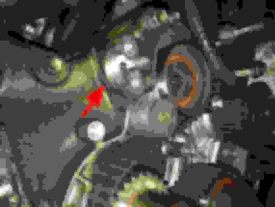
Remove the timing belt cover spacer
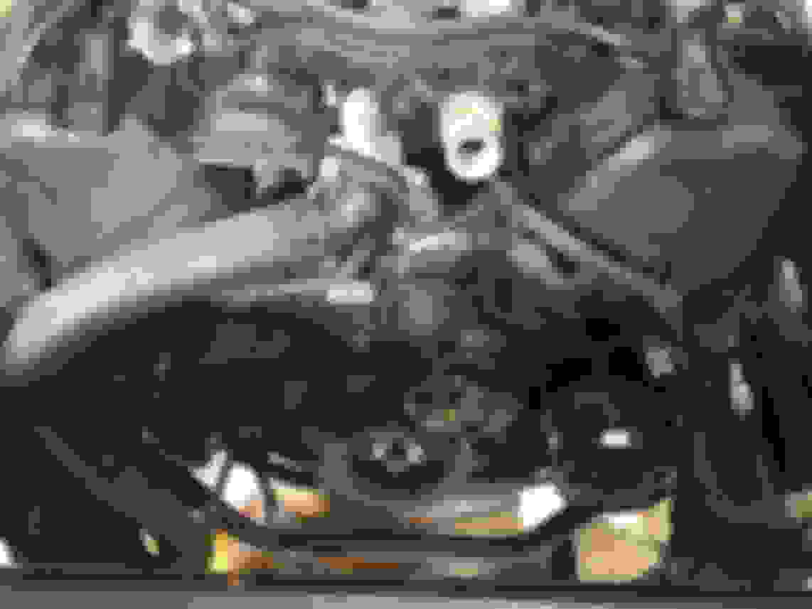
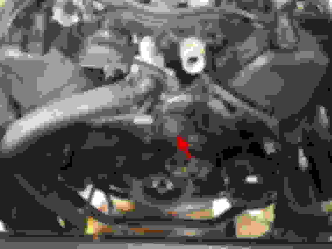
It's just a piece of plastic that integrates into the timing cover system. This is where you're at after removing the pulley and lower timing cover. This is the timing belt guide as well as toner ring for the crankshaft position sensor shown at 4:30. The red arrow is pointing at the timing belt cover spacer.
Remove timing belt hydraulic tensioner
The hydraulic tensioner resides in the vertical position just to the passenger side of the crankshaft. Alternately loosen the 2 bolts on the hydraulic tensioner. This will allow the tensioner to evenly release tension on the belt. Once it's fully released remove it from the engine. The tension is now off your timing belt.
Photo shown with tensioner removed.
Remove timing belt
Slip the timing belt off the cam pulleys, water pump pulley, and 2 timing belt idler pulley's.
Remove crankshaft timing pulley
Again, usually no puller required here. Sometimes they slide right off and other times they stuck a little bit. All i ever have to do is put a pulling force not the pulley with my fingers and tap the pulley with a dead blow. The dead blow hammers head is urethane so it cannot damage the pulley. DO NOT use a metal hammer. Timing pulley removed showing this engines leaking crankshaft seal.
Remove the LH idler pulley
Remove the bolt and idler pulley then set them aside together.
Remove the RH idler pulley (tensioner assembly)
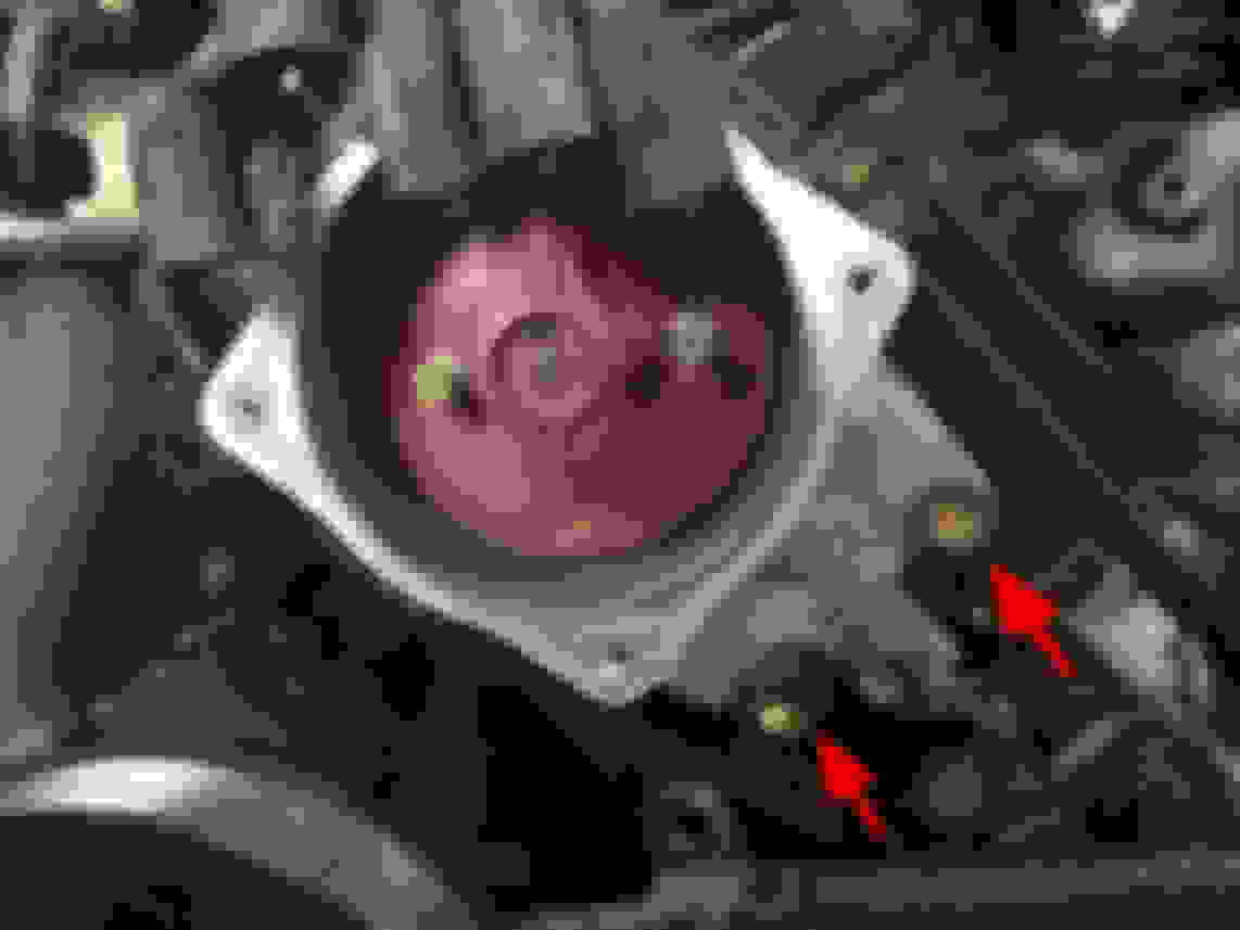
This is where your 10mm hex bit socket comes in. Remove the tensioner assembly after that bolt is removed. There is a washer between the engine and tensioner assembly so do not lose it. That must go back in place when reassembling.
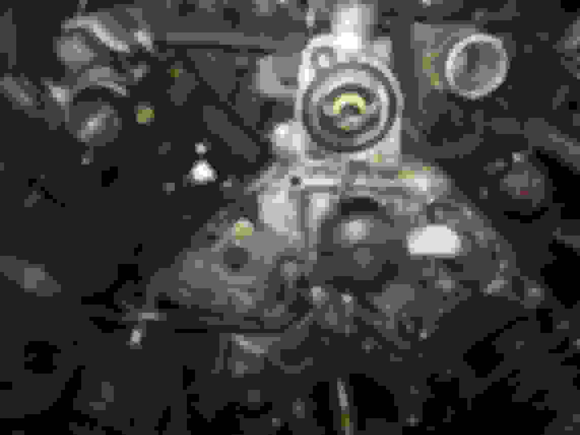
This is where you're at now, if you removed your cam pulley's to inspect and or replace the cam seals. If you want to do that you'll need to also remove the 2 bolts on each side and remove the timing belt rear plates to access the seals.
Remove the 2 bolts and slide the front spring clamp back the middle of the hose. This thing is usually in there pretty good so you aren't just pulling it out. Again with the dead blow hammer. Hit the back of the 17mm bolt head with the dead blow while pulling up on the inlet housing. It will slowly tap out of there. The dead blow is so great for this because it doesn't damage anything with it's urethane head face.
Clean up the inside of the coolant crossover where the large o-ring from the inlet housing rides
Sometimes there is a leak here and flakey coolant goo can get built up there. You can lightly run a scotch-brite pad inside where the o-ring rides to make sure it's smooth or pick anything in there off with your finger nail. Don't worry about cleaning any gasket off the water pump as it's getting replaced.
Remove water pump
Place your drain pan under the front of the engine. Remove the 5 bolts, 2 studded bolts, and 1 nut. Hopefully you have the nuts from previous parts back on the studs for organization purposes... You'll need to remove those temporarily to remove the water pump.
Clean water pump sealing surface
You can carefully use a razor blade her to clean off the water pump sealing surface. This is aluminum and scratches very easy so take your time here and be very careful.
Replace bypass pipe o-ring
Replace the bypass pipe o-ring with the one supplied in your kit. You will lubricate it with soapy water when reinstalling. If you do no not lubricate the o-ring you could potentially pinch the o-ring and this NOT a place that you want a coolant leak when you're all done...
This is why you lubricate the o-ring and reinstall the new water pump carefully. This is the definition of a pinched o-ring. How this wasn't leaking I have no idea... New o-ring sitting pretty.
This ends the disassembly process. You've turned the corner and will begin reassembling now.
Place the supplied gasket in the Aisin kit on the front of the engine. It only goes one way. I really like this style of gasket rather than FIPG'ing the water pump on like the old days. Then set the water pump on and install the 5 bolts, 2 studded bolts, and 1 nut on just slightly snug. I like to slowly tighten each fastener a little more in several passes until they are all fairly snug, then applying the correct torque.
Torque the 8 water pump fasteners to 13 ft-lb.
New gasket waiting for the new water pump
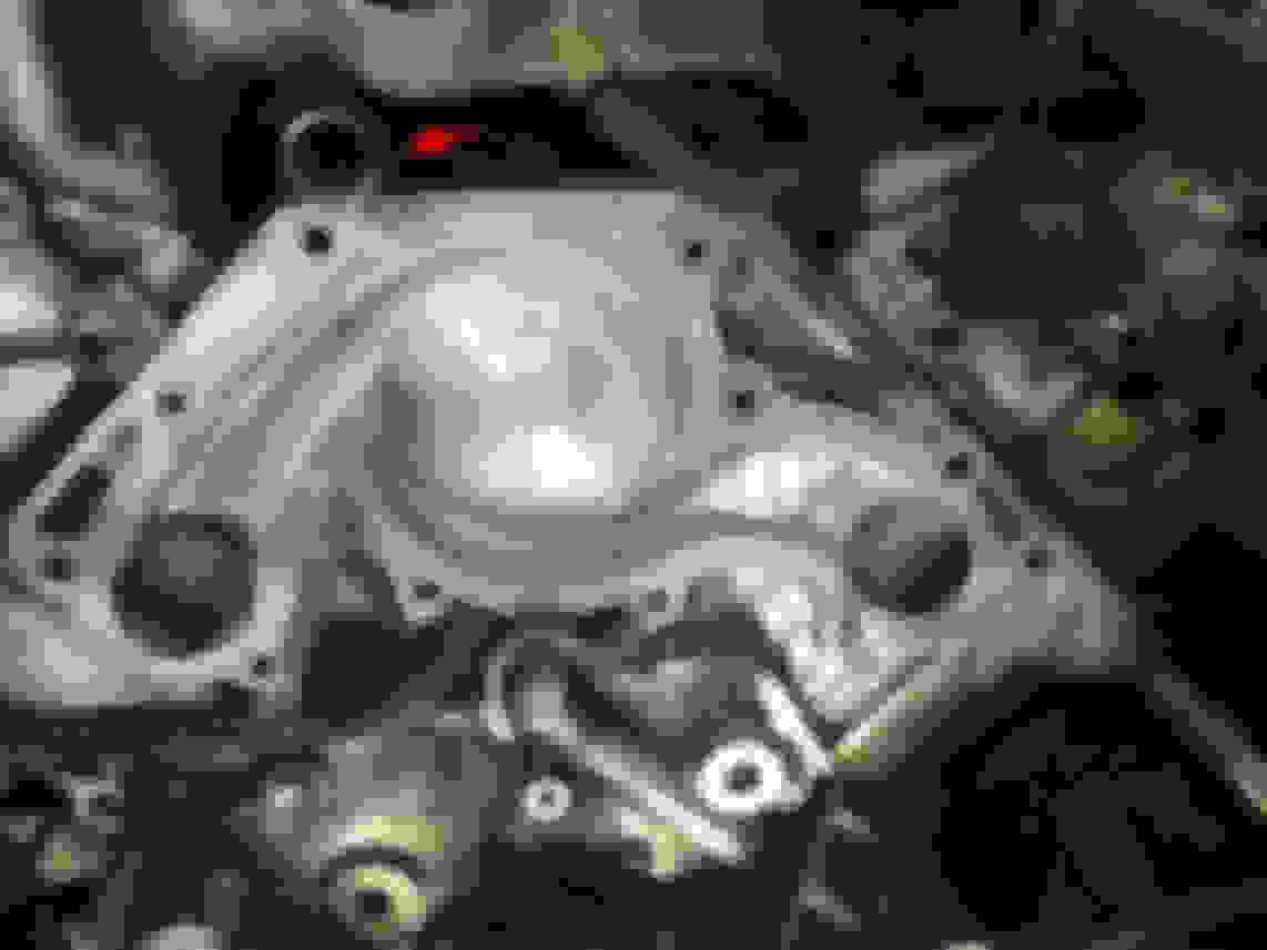
Install coolant inlet housing
Clean the groove in the inlet housing sealing surface with a pick or something until it is totally clear. Then you will need to apply a 2-3mm bead of FIPG in the groove with the nozzle attached to the tube of FIPG. I always clean the nozzle back out with a little pick or something and remove as much FIPG as possible so I can reuse the nozzle multiple times. You want to lay a thin bead of FIPG inside the groove that barely protrudes above the surface. If you go crazy with the sealant it will squish out everywhere and will be a huge mess. These sealing surfaces are highly machined and a little FIPG goes a long way. Try to copy what I'm showing in the photo. You'll see the proper amount of 'squish' when it's torqued down.
Be sure to replace the large o-ring with one supplied with your new water pump. Lubricate the o-ring with a very soapy water solution.
When installing you'll need to make sure you put the nipple back in the small coolant hose. Set the neck in the coolant cross over hole, install the 2 bolts with your fingers and run them down until they're snug. You will need to tap the front of the inlet housing while you are alternately tightening the 2 bolts down. Eventually you will bottom out and you can torque the bolts. Be careful not to disturb the FIPG bead while installing, One part of the sealing surface may touch before the other but try to get them to touch as squarely as possible.
Torque the 2 inlet housing bolts to 13 ft-lb's
Go ahead and slide the spring clamp back into it's final resting position on the small coolant hose connecting to the inlet housing. Try to get as nice of an even bead as you can, Don't make it too thick or it will just squish out everywhere.
Tap here while alternately tightening the 2 bolts to drive the housing into the crossover.
The perfect squish of FIPG after the final torque is complete.
Apply blue loctite to 2-3 threads of the 10mm allen bolt. Install the bolt, tensioner pulley assembly, and spacer washer on to the engine.
Torque the 10mm allen bolt to 25 ft-lb
Ensure the assembly pivots at the bolt smoothly and that the pulley rotates smoothly.
The way you install the timing belt is a personal preference. I usually install the tensioner pulley assembly first, route the belt, line up the marks, then install the timing belt idler pulley.
Familiarize yourself with the timing belt markings on the belt and pulleys
The belt will have printed markings on it to line up with the pulleys for installation. Keep in mine that once the engine is turned over even once after assembly the the printed markings are gone and won't line back up for a very large number of revolutions that I don't even feel like calculating right now. After rotating the engine you will only be looking at the crankshaft pulley mark to the timing cover mark and the cam notches to the timing belt rear plate marks. You will notice in my photos that I installed the belt 'backwards.' I've got it so the L CAM marks on the belt line up with the passenger side cam and the R CAM mark with the drivers side. This is technically incorrect. But it doesn't matter which way you install the belt as the marks are symmetrical from the crank mark. I guess my brain likes seeing the arrows pointing towards the cam timing marks. I'm surprised this happens sometimes with how particular I am when wrenching but it's all just temporary marks for ease of assembly anyway. If that's the biggest mistake I make during a timing belt job I'll take it. Crankshaft timing mark.
Right cam mark lined up with the notch in the right cam pulley. *They do not line up with the timing belt rear plate mark because the crankshaft is set 50 degrees ATDC.
You can see how the cam pulley notch here on the left cam pulley lines up with the printed belt mark. *They do not touch because the crankshaft is 50 degrees ATDC
Crankshaft mark lined up with notch in the pulley.
The notices on the cam pulleys are pretty easy to see but the one on the crankshaft belt pulley isn't so easy to see. They are usually filled with crud and need to be cleaned out to see easily. Do not confuse the larger notch that lines up with the crankshaft key. That's not it.
Just slip the pulley on the crankshaft, after replacing the seal if need be or course. DO NOT turn the crankshaft at all for any reason until the marks are all lined up and the tensioner is installed and putting tension on the belt.
Install timing belt
Start by lining up the crankshaft timing mark on the belt with the notch on the pulley. Then route the belt over the tensioner pulley assembly and around the RH cam pulley. Use a 17mm socket with a breaker bar or ratchet if you don't have one and turn the cam to line up the marks. Here the marks will not touch each other because we have the crankshaft set at 50 degrees ATDC to prevent any possible piston to valve contact. You count the teeth or use the slack in the belt to actually touch the mark with the notch then move on. Now route the belt under the water pump pulley and around he LH cam pulley. The mark on this side lines up nicely with the crankshaft in this position. Somewhere in here you may here a pop which is the belt skipping a tooth. Check the RH cam for a skipped tooth and possible misalignment.
install new timing belt idler pulley
While holding tension on the belt with the marks all lined up, hold the tension of the belt with your thumb where the timing belt idler pulley goes and install the idler pulley. You need blue loctite on 2-3 threads of this bolt as well.
Torque timing belt idler pulley bolt to 25 ft-lb's
At this point the belt is on there tight enough to where it should skip any teeth easily but don't do cranking not he cam pulleys or anything like that.
Look over your timing marks one more time, especially the RH cam marks since they do not touch.
Install hydraulic tensioner
With the pin still installed in the hydraulic tensioner, install it on the engine. It will sit in far enough to get the 2 bolts started. Alternately tighten them in several passes slowly drawing the tensioner up until it bottoms out. You'll see the tension on the belt tighten up.
Torque the 2 hydraulic tensioner bolts to 19 ft-lb's
Install timing belt cover spacer
Install the plastic wedge shape spacer that you took out on disassembly.
Install timing belt guide on the crankshaft
Make sure you install the timing belt guide in the correct orientation
Install lower timing belt cover
With the 4 10mm bolts, install the lower timing belt cover to the engine around the crankshaft.
Install crankshaft pulley
The pulley should just slip right on after lining up the crankshaft key with the key notch in the pulley.
Install the crankshaft pulley bolt and snug it down but don't worry about final torque just yet.
Check timing marks one final time.
Turn crankshaft over CW just under 2 revolutions until the white line on the pulley lines up with the zero on the timing cover. With the crankshaft back at TDC check your camshaft pulley markings compared to the timing belt rear plate bumps. Remember, the printed marks on the belt are now meaningless. Crankshaft mark on zero
RH cam pulley notch lined up with the rear plate bump.
LH cam pulley notch lined up with rear plate bump.
Torque crankshaft pulley bolt
Now torque that monster down. This is where the awesome crank holding tool comes back into play. Hold the crankshaft via the method of your choice and torque her down.
Using the 2 nuts and 2 bolts, install the fan bracket.
The 12mm head fasteners torque to 12 ft-lbswhile the 14mm head fasteners torque to 24 ft-lbs
Install the LH ignition coil
Install the ignition coil to the LH cylinder head and fan bracket. I say do this now because it's much easier with the compressor still setting out of the way. Connect the coil to the harness via the black connector under the coil and connect the high tension cord when it won't be in the way.
Install drive belt tensioner
With the 1 bolt and 2 nuts, install the drive belt tensioner.
Torque the 3 drive bent tensioner fasteners to 12 ft-lbs
Install the alternator
Slide the alternator over the long stud after the drive belt tensioner goes over that same stud. Install alternator with 1 nut and 1 bolt.
Torque the 1 nut and 1 bolt to 29 ft-lbs
Install AC compressor
Using the 3 bolts install the AC compressor after hanging the compressor by the black hook back on the fan bracket. If I recall correctly there are different length bolts. I think the longest bolt is the top front one. The bottom front bolt first goes through the plate the the ground cable is bolted too. Then the nut also holds that plates to the compressor. Then there is the rear bolt that is accessed with the long extension through where that plastic side cover goes. After the bolts are torqued, don't forget to clip the harness retainer back into the little hole that you released it from earlier.
Torque the 3 bolts to 36 ft-lbsand the 1 nut to 22 ft-lbs Insert this retainer back into the hole after torquing the bolt down.
 10-22-16, 07:07 PM