When you click on links to various merchants on this site and make a purchase, this can result in this site earning a commission. Affiliate programs and affiliations include, but are not limited to, the eBay Partner Network.
Disclaimer: Installation was completed on a 2013 Lexus GS350 F-Sport. This tutorial could be used as a reference against other models. It's always recommended to verify all connections via wire diagram.
Extra Parts Needed
Part# 93567-A5014 (Fog Light Screws) x 4
Part# 82998-12870 (N28 Connector Pins) x 2
Part# 82998-24350 (BA2 Connector Pins) x 2
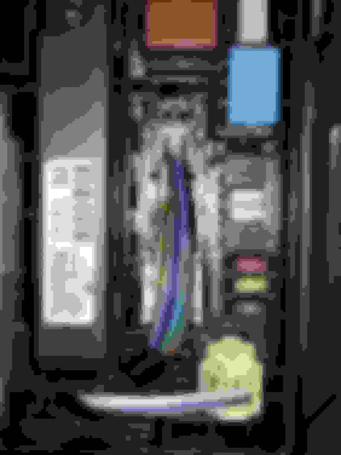
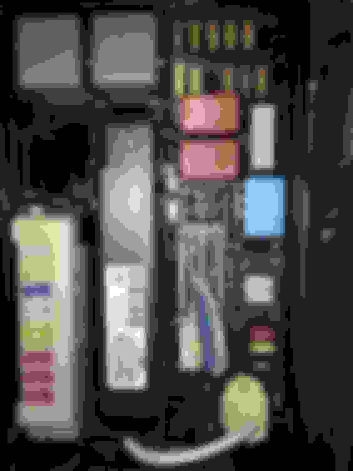
You will notice an integration relay unit and wire harness
This will be the main wiring harness that you will be tapping into
Two white wires have been added to power the fog lights. I combined both wires together and connected it to the positive side of the relay harness.
This will be a similiar relay harness provided in your kit. The red circle indicates the part in which I cut off. You will be left with a postive and negative wire going to the left and right plug.
Running wire from driver side to passenger side (provided by member 4matador)
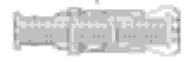
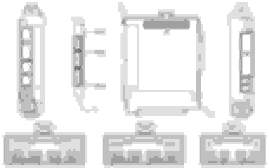
BA2 Connector (Relay/Fuse)
N28 Connector (Fog Light Switch)
Area to access main body ecu (red circle/behind coin tray)
N12 Connector (Main Body ECU or Multiplex Network Body ECU)
I did not bother to purchase a pin for the N12 connector. I ended up pushing in the wire I extended from the foglight switch and zip tieing it down.

 02-04-16, 12:02 AM