When you click on links to various merchants on this site and make a purchase, this can result in this site earning a commission. Affiliate programs and affiliations include, but are not limited to, the eBay Partner Network.
I am starting a build thread for converting my auto 1JZ SC400 to a CD009.
Here is parts list Also, check the bottom of this post for an excel spreadsheet of parts and hardware and costs:
-CD009 from 2006 350Z with 63k miles on it. It has AZQ CD009 label on it, and CD0 #2 cast in the casing, signifying that it is the latest revision of the CD009
-Collins adapter kit which includes: 670ft lb clutch kit with pressure plateReceived with kit, but I will instead be running South Bend clutch kit NSK1000-SS-TZ with silent disc
Adapter plate
pilot bushing adapter
trans mount
aluminum driveshaft
driveshaft yolk adapter for SC400 diff
bolts and hardware
extended clutch release bearing and sleeve
-pedal set
-new master cylinder, hard line, slave line Went with a Wilwood 3/4" master cylinder, a hard line from advanced auto that I bent, and a custom stainless braided slave line from Pegasus Auto
-new throw out bearing, bearing sleeve, slave cylinder, and cast iron clutch fork? (I will check the condition of these components when the cd009 arrives)The Collins kit comes with a throw out bearing mounted on an extended sleeve, so you can not use the stock release bearing apparently. My fork and pivot ball look to be in good condition, so will leave as is. Gott a new OEM Nissan slave cylinder
-240sx shifter with BRZ shifter for reverse lockout functionality
-MO-LITH No.2 grease made by Lubriplate. It is Lithium grease with Molybdenum Disulfate, which 350z clutch manual specifies to use such grease type. Got from partsgeek for about $15 with shipping.
-cd009 bellhousing to Collins adapter mounting bolts: (5) M12X1.75-55mm and (4) M10x1.50-35mm bolts
-98-00 SC400 gated shifter trim bezel
-VQ35 reverse switch connector with pigtails from Wiring Specialties
I will be taking lots of pics and making lots of posts of what I will encounter..
First things first: drop auto trans:
-remove drain plug and drain fluid: Also drain fluid from the trans fluid cooler feed and return lines and cooler(s). I just disconnected the feed and return lines rubber hose at the front near the engine and blew compressed air through to empty out the lines and coolers
-while fluid is draining, begin removing driveshaft. Remove driveshaft mounting bolts from diff, and remove driveshaft isolator mounting bolts:
-remove 2 bolts holding the center carrier bearing support
-Driveshaft will now pull out of the diff
-disconnect gear shift lever linkage
-remove bolts fastening the flywheel to the torque converter. These are removed via the inspection plate located at the front bottom of the trans bellhousing.:
you will need to put a 22mm socket and breaker bar on the crankshaft pulley bolt and spin it CLOCKWISE to access all of the bolts. It will be easiest to have a friend hold the breaker bar on the crank pulley bolt while you break the bolts loose through the inspection plate, but you can also do it by yourself by grabbing the breaker bar with one hand, and breaking loose the bolts with the other
unclip all connectors:
Begin removing all bellhousing bolts fastening transmission to engine. There are 4 along the top that are hard to get to and will require the use of a series of extensions to reach them from the back of the transmission. One of them will be a 14mm bolt (the top starter bolt). The other 3 will be 17mm.
Here is my extra long 1/2" extension set, Titan 12081. They are 30", 24", and 18". $25
Here is a pic of my series of extensions to reach one of the top bolts
After removing all bellhousing bolts, place a transmission jack under the pan and jack it up to provide slight pressure on the trans. Then remove the bolts to remove the crossmember
Also, remove the transmission dipstick and dipstick tube. Since I have a 1JZ and the 1JZ auto trans has cable controlled line pressure, I had to also remove the cable that is fastened to the throttle body. 2JZ GTE auto's do not have this cable to remove because the line pressure is controlled by the ecu via solenoid. You will also need to remove the 2 transmission cooler lines on the passenger side of the transmission. I have no intentions on re-using or selling the trans, so I just cut them because those lines have a reputation for being pretty frozen on
You should now be able to carefully stick a screwdriver in between the block and the trans bellhousing and pry them apart pretty easily. Then I used a pry bar to get the trans out as far as I could. Then I wiggled the trans out. I had a heck of a time, but eventually came out
Here is the auto flex plate
Time to remove the auto flexplate and change the rear main seal. Remove the 8 bolts fastening the flex plate and remove the flexplate and spacer plate behind it. Here is after removing the flexplate and spacer:
It's hard to tell in the pic, but the rear main seal that's in there is just about flush to the retainer plate. I removed it by gently prying it out with a flat head screwdriver, with the tip taped with electrical tape. Next, wipe the inner diameter of the new seal with multi purpose grease. Just a thin coating is all you need, you don't want any getting into your oil. Put it on the crank and gently seat it a little bit, then grab that spacer that was behind flexplate and put the spacer over the seal and tap it in. This will get it flush to the crank. Then, put the old seal over the new one and tap it in further until its seated where you want. I have read that ideally it is supposed to be flush with the chamfer. In my case, the original (not sure may have been changed already???) seal was flush with the retainer plate. I have also read, which makes sense, that when installing a new seal, not to put it in the same position that the last one was in, because over time, the seal can put a slight groove in the crankshaft. So put it in a different position so that oil cant get past that slight groove. So, I chose to tap it in until flush with the chamfer. You can see the chamfer:
Next, I have also read to put a bead of FIPG around the outside diameter to even further prevent leaking around the O.D. of the seal. Do not apply to the inside diameter, since the crankshaft rotates on that surface (obviously)
After installed, put a 22mm socket on the crank pulley bolt and give it a couple clockwise turns to turn that crank on the new seal. This will help even out that tiny coating of grease around the entire seal. I also removed my trans coolers, but nothing special there so didn't bother taking pics. Next, I have to get the Collins kit and test fit the trans in to see how much tunnel banging I will have to do. If I am lucky enough, I will not have to do any. But that's doubtful..
I test fit the adapter plate up to the block and first try the dowel pins on the back of the block don't seem to really want to go into the holes on the plate. I brought the plate in the house to warm up and see if the some expansion will help. The dowel pins on the adapter lined up good with the cd009 and went in. That's one thing that I was glad to see on this adapter were the locating dowel pins. They will make sure everything stays centered while assembling the trans to the motor. While checking the fitment to the cd009, I noticed that the trans will have to mount to the plate using a couple of those holes that are right on the edge of breaking through the plate, so not happy with that at all... I installed studs in the adapter plate for the starter. If I had to do it over again, I would use both nuts and tighten them against eachother to tighten the studs into place, rather than just tightening the nut down to the shoulder to thread the stud in. Now I can't get the nut off without unthreading the stud We'll see when the Loctite cures how the nut comes off:
EDIT: I was not able to fit the plate in with both studs threaded in. I had to remove the top stud, fit the plate, and then thread the stud in from the back
Here is pic of hardware nice and separated and labeled in individual bags, and also the release bearing/sleeve and pilot bushing adapter supplied by Collins. The release bearing almost looks used. The face of the bearing has abrasions on it, like it has been in contact with a pressure plate already, and the bearing looks dirty. So also not happy about that at all...:
I Started getting the cd009 ready. Removed the shifter, Nissan trans mounts, and release bearing/sleeve and fork
Remove 3 bolts and small black bracket on driver side of trans:
Remove 4 bolts holding shifter housing extension
Remove bolt on linkage under shifter inside rubber boot
Remove shifter and thread screws back into their respective holes in case needed later:
Remove the release bearing/sleeve/fork as a whole. Just pull it forward, and it will slip right off of the shaft. The clip will keep the fork attached. When the assembly is removed, the fork can just be rotated off of the clip.
Trans with fork and release bearing/sleeve removed:
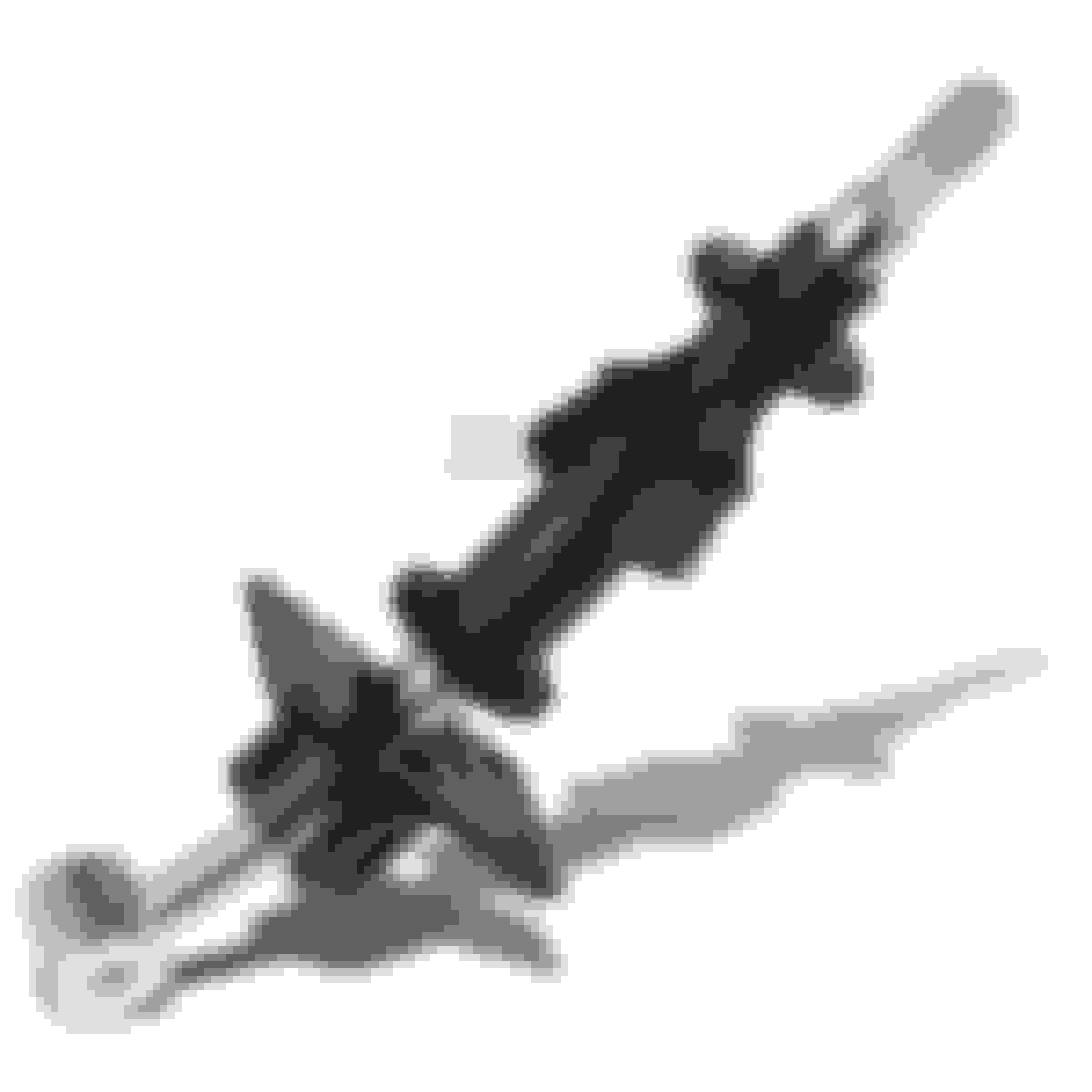
Here is a pic of the Nissan OEM release bearing/sleeve (on the right) next to the Collins supplied release bearing/sleeve. You can see how Collins supplies an extended sleeve/bearing assembly. I'm willing to bet that it is a standard part for another transmission because it doesn't appear to be modified. But I haven't looked that close yet to be honest
Before fitting the adapter plate, remove this screw in the coolant tube mounting bracket so that the coolant tube can be pushed upward when tightening the plate because the plate interferes with the tube in it's current position:
Fit the plate. I had to maneuver the plate around the downpipe to get it above the downpipe. This makes me think that I will have to remove the exhaust, which I was hoping to not have to do. But you can see there's not much room there by the downpipe. I had to put a little bit of grease on the dowel pins, and started hitting the plate with a rubber mallet to bring it in a little. Then, used a hammer to lightly tap around the plate in a star pattern to seat it. Then, install screws that came with Collins kit with Loctite. I used removable Loctite Blue 242. All holes lines up with no issue
Here is a pic of the coolant tube after seating the adapter plate
Getting ready to mount starter. You have to drill out the threads on the starter mounting flange so that you can mount starter on the studs that you installed into the adapter plate. Use 15/32" drill bit
Install starter onto studs and fix starter with nuts. It is a tight fit up against the fuel dampener behind it, but you can get it in there. The studs don't have to be as long as they are.. You may have to unclip a sensor and push some wires and tubes out of the way. The top nut is a PITA to try and get any tool on. I had to buy a set of stubby ratcheting wrenches, and was able to tighten down the nut. Starter mounted:
I determined that I didn't have to actually remove the exhaust, just had to remove the V band clamp on the downpipe, and then removed all of the exhaust hangers, then was able to get it out of the way to make room for test fitting the trans:
Make sure to remove any O2 and/or wideband sensors
Now can move exhaust out of the way
I had to cut the auto shifter lever out:
Now can try to test fit the trans......FAIL. This is going to be a tiiiiiigggggghhhhhttttt fit:
Strip the exterior of this thing down. Take every bracket off that isn't needed, and anything that sticks out beyond the body of the trans, take care of:
Cut this connector back, and remove that little bracket. You cant just remove that sensor because it is an oil passage.
Remove this bracket
Sensor cut back:
Remove the wire harness brackets on bottom of trans:
These are the 9 bolts that will be used: (5) M12X1.75-55mm and (4) M10x1.50-35mm. You will need to purchase these, they are not included in the Collins kit. I have added them to Post 1 parts list
I HATE the fact that 2 of these holes on here that we have to use are just on the edge of breaking through the edge of the plate. Makes no sense that ANYONE would consciously design this. Here is one of them. On the driver side. One of only 2 mounting points on the driver side of the trans. The other mounting point on this side isn't even a full hole. It shares half a hole with another hole, like a number 8.. Horrible design. I understand that he is probably trying to use the adapter in multiple applications, but this is just flat out stupid. I can't understand why he couldn't have given just an extra 1/4" of wall on these holes...
I had to beat in a little along the top where the top mounting bolts are going to be, and also by the mounting bolts on the driver side. I am really hoping that I don't have to do any more beating. It's a PITA. I should be able to get to the passenger side bolts pretty easily, so didn't have to pound there. Also pulled a little bit of insulation off the firewall.
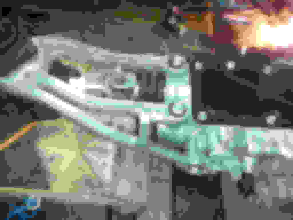
Here is a top view through the bay of the top bolts. I'm going to try my best to get to these bolts through here. Looks like I might just be able to do it. Won't be fun, but I really don't want to touch the motor at all. I will have to tape the bolts in place when I shove the trans in, then I should be able to reach in there and thread them in
You will also need to drill out the threads on the cd009 bellhousing of the lower 2 bolts. The Collins adapter is threaded, so you should drill the threads out on the trans. Used a 25/64" drill bit:
I decided to do some work inside the car today. I removed all the guts from under the shifter trim bezel. First remove the trim if not already removed:
Remove 4 bolts that are holding down the plate:
You will also need to unclip any connectors and anything else that will prevent you from pulling the plate out. Here is the plate out. I will cut a piece of this off to retain a couple mounting points for the trim
Here is a pic of under bezel trim with everything removed:
Mounting the clutch: The pilot bushing did not fit into the flywheel, so I went around the outer diameter with some 400 grit sandpaper by hand: (Thanks for the tip NOLAGG)
Seat the bushing in the crank and tap it in with a hammer and piece of wood. I tapped it in until there is about a 1/4" gap between crank and inner face of bushing flange. This will get the outer face of the bushing just about flush with the Collins adapter face. The input shaft of the trans sticks out further than the face of the bellhousing, so I will have that much engagement with the adapter, which is probably 1/4" or so. If I could do it again, I wouldn't tap the bushing in as much. Maybe about 1/8" or 1/4" less, but will be fine as is:
After tapping it in, there may be some chips where the bushing presses into the crank that you will want to scrape away with a tiny tip screwdriver:
Here is pilot bushing installed:
Time to mount flywheel: Put socket and breaker bar on crank pulley bolt and put up against passenger side frame so that you can torque down on the flywheel and pressure plate bolts without turning the crank:
Place flywheel up on pilot bushing. LOCTITE on flywheel bolts. The bolts will only engage the first probably 7-8 threads, so put the Loctite on like threads 2-4. It is important to put a generous amount on, and wrap all the way around the bolt because the Loctite will serve two purposes on these bolts. It will keep them from backing out, and will also act as a sealant to seal the threads because the flywheel bolt holes are open to engine oil and can leak oil from these bolts if not sealed. This is also why I used blue Loctite 242 on these bolts, rather than red, because I knew that I was going to be using a lot on them, and that much red Loctite will be tough to break these bolts loose in the event that they need to be taken out
Fasten all flywheel bolts: The Collins kit comes with ARP flywheel bolts. Collins install instructions says to tighten to 56ft lbs. Driftmotion sells ARP flywheel bolts and suggests 75ft lbs. So, I installed to 70ft lbs in a star pattern in 10-25-40-55-70 torque increments. Once mounted, I wiped off the friction surface of the flywheel with a paper towel sprayed with brake cleaner
Here is clutch disc. There is print on it indicating the transmission side:
Put the disc up on the flywheel. Make sure not to touch the disc surface. When grabbing it, grab by the center hub. Place the alignment tool through the disc. The alignment tool will then go into the pilot bushing, keeping the disc centered and in position
Mount pressure plate over disc: First wipe down the pressure plate/clutch disc mating surface with a paper towel sprayed with brake cleaner. Repeat until all grime is removed. Put pressure plate up on the flywheel dowel pins. Put a dab of Loctite on each of the pressure plate bolts and tighten in a star pattern. The 350z service manual says to tighten to 29 ft lbs in 2 steps, with first tightening to 11ft lbs. So that's what I did, 11 then 29ft lbs
With the adapter and clutch components mounted to the engine, time to start working out a shifter solution. Ended up going with a 240SX short shifter and housing chopped with a BRZ shifter welded on to utilize the reverse lockout feature of the BRZ shifter. Also, using the 98-00 SC gated shifter bezel trim, the shifter is more centered. Thanks to Ali_SC3 for figuring much of this out prior.
Here is 240sx shifter:
Here is BRZ shifter:
Here is gated shifter trim next to 5 spd trim. You can see how the centerpoint of trim is moved down by 1.5-2":
Scribe crosshairs for centerpoint of mounting holes and drill. Scribe a line at 13/64" from the edge. The other line at about 4-5/16" from the edge where the shifter is, and that will give you your cross hairs center point. Also, I cut the shifter housing back at about 4-11/16" from that edge. I could've left about another 1/8" on, so 4-13/16" should be good:
Modify linkage so that you can use the bottom hole of the component mounted on the shift rod for the 240sx shifter "cup" to sit and swivel in to change gears. I wanted to remount the linkage as far up the rod as possible, so using a dremel, shaved back the welds on the linkage part and drill holes in the same exact location, except as close as possible to the linkage so that the linkage can be placed furthest up the shift rod as possible
Using step drill bit, drill hole just large enough that the cup sits in:
Shifter test mounted. I used 10 washers as spacers and taped them together to keep them together. Also notice that I had to shave off some of the top of that circle above the brass piece to flatten it out so that the shifter mount plate can sit better:
Have shifter bushing sitting in the linkage hole surrounded by JB weld on both the top and bottom. I centered the bushing so that there was about the same amount sticking out from the top and bottom. Have to let it cure for 24 hours. Put an electric heater pointed right at it so hot dry air helps it cure as best as possible.
I scraped up the bushing surface and linkage surface with 80 grit sandpaper, then washed with soap and water, dried it off, then wiped down with Acetone to have a nice clean and grease free surface for the JB weld to bond to. Came out strong. We don't want that bushing to move around at all, just the shifter tip ball to move around inside of it.
I figured out that the stock remote shifter frame can be chopped up and used as support for the 240sx shifter housing:
Everything mounted:
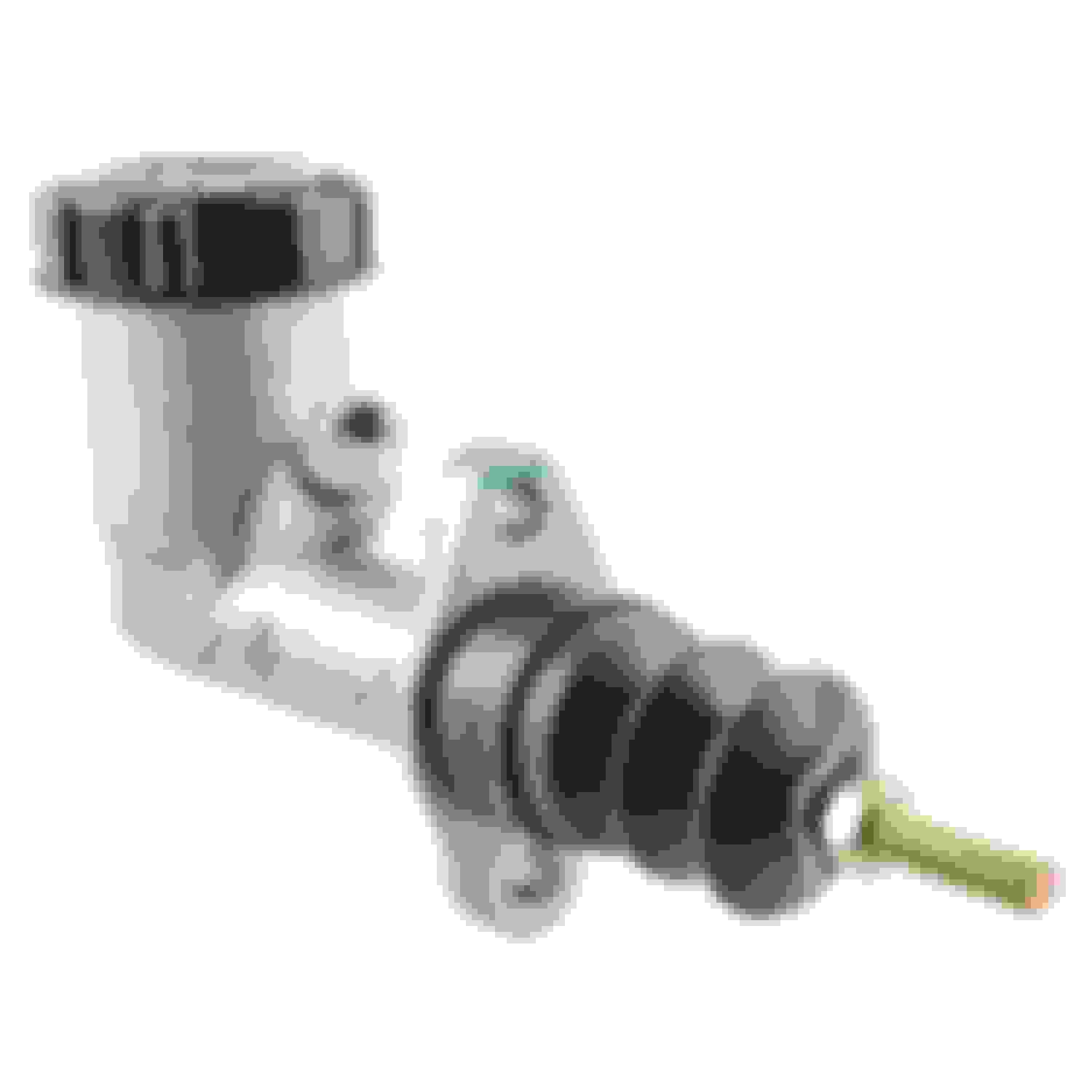
I will be using a Wilwood 3/4" clutch master cylinder like this:
Here is a pic of where the clutch pedal will be mounted. I have read that there will be a little diamond imprinted in the foam where the clutch pedal mounts. I drilled those holes for the wires a few years ago, so can't remember if that is the case or not. Not much room in there, gonna be fun.. I will have to remove that bracket that's in the way there to get more room.
Drill/punch out the mounting holes for the clutch pedal / master cylinder:
You can see that the clutch pedal assembly holes are pre-marked on the firewall. You can see the outline for the large hole, and you can see the outline for the bolts.
These two holes here were already drilled from before because I was running some wires through to the bay. Luckily the smaller hole was drilled perfectly through the marking for the clutch pedal bolt. You can see the marking for the other clutch pedal bolt just up and to the left of the big hole.
You have to unclip the wire harnesses from the tilt and telescoping wheel control unit, and remove the bracket that its mounted to in order to make room for a drill to drill out the holes. I used a drill for the other bolt hole that needed to be drilled, and I used a knockout punch for the large hole.
I had to take flush cut snips and snip down the bushing flush to the clutch pedal because the clevis fork rod end that I am using with the Wilwood master cylinder is narrower than the stock one. There will be more to come with this master cylinder prep / install when I get all the parts in:
Here is pic of me mounting my cardboard template so that I can center punch the holes for the Wilwood:
Then had to open up the hole on the clutch pedal and drill the holes to mount the Wilwood:
Then had to notch out a piece of the clutch pedal so that the head of bolt can sit flush on the inside. Here is pic before dremeling it out:
Next 2 pics are after cutting out the notch:
Here is pic of the OEM MC and the Wilwood side by side. Both have the clevis ends threaded to the very last thread. They have the same exact throw and adjustability using the clevis fork rod end that I got from Mcmaster Carr part #1583K13
Here is a pic of the hardware on the clutch pedal assembly in order to mount the Wilwood master cylinder:
This was the hardware used:
Mounting pedal assembly to Firewall (the hardware that is kiddie corner to eachother and going through the black extruded standoffs on the pedal assembly):
-M8x40mm bolt, 2 flat washers, 2 nuts, 1 lockwasher
-M8x55mm bolt, 1 flat washer, 1 lockwasher, 2 nuts (this was the bottom. Probably could've just used the same bolt as the top though)
Here is the MC mounted. What a pain. Tight spot, but looks good in there
Cut out the tunnel for the shifter. I cut it larger than required because I want to be able to remove the shifter easily if needed. This way, I can just remove a few bolts and pull it up through rather than having to drop the transmission. I will then get a sheet of metal and weatherstripping and make a cover for the hole and shifter.
Now, time to try to get the trans in. Started off with brake cleaner and removing all residue of old grease. Then greased all the grease points with Lubriplate MO-LITH No.2 grease. It is Lithium based grease with molybdenum disulphide, which is what the 350z manual calls out. All moving parts get just a slight coating, non moving points get a more generous amount. Don't want the grease flinging off of the moving parts..
Install the holder spring onto the Collins extended throwout bearing, and install the shift fork to it:
All cleaned up and lubed and ready to go:
Tried everything in my power to get this trans mounted with motor in bay. Tried tilting motor all the way back. Even removed motor mounts to try and get more tilt. Just not enough room. The tunnel needs to be spread:
Still, no go. The clutch components stick out way too far and can't get the fat part of the trans where it needs to be (the deep part of the firewall) because of how far out the clutch is
Had to pull motor. No other way to do it. While out, I beat the firewall and tunnel in with sledge. Just be careful because the heater core is up there somewhere too...
While motor is out, I also deleted the AC, did some wire tucking, painted bay, and some other things irrelevant to the cd009 swap so will not mention here on page 1, but read through the thread if interested.
This is the shift lever position switch connector that fastens on the passenger side of the auto trans. The neutral safety switch wires are the black and black/white wires on the top/middle of the connector (that yellow part of the connector). The reverse wires are the black/red and yellow wires:
NSS wires snipped:
Soldered and heat shrunk:
The red/black and yellow wires for reverse:
Trans mounted to adapter/block:
Motor goes back in at this point and with trans still supported by jack, mount the crossmember. First mount the insulator: I torqued to 40ftlbs:
Then put the crossmember up and tighten less than hand tight:
Tighten the crossmember to the insulator, then go back and torque down the crossmember mounting bolts TSRM says to mount trans crossmember to body at 19ft lbs:
Here is a pic of where the fill hole plug is. I was worried with how tight and beefy the trans was, that it would be difficult to add the trans oil, but is easy enough to get to with a quart bottle pump:
Diff adapter mounted. TSRM says to mount propeller (driveshaft lol, but they call it the propeller) to diff at 58 ft-lbs. This diff adapter seems to be a very good design. There was basically no tolerance when slipping it onto the diff carrier. Fit perfect
Driveshaft slip yolk went right into the output shaft of the trans perfectly and here is driveshaft mounted to diff adapter. The bolt heads were a tight fit against the u joint linkage, but still able to get them on. You can not get a socket in there, so I just doubled up on wrenches to get some leverage on the bolts
Driveshaft installed:
New OEM slave cylinder and braided clutch line to hard to line:
And this is how much more room I have on the firewall for in case I ever have to take this trans out again. I don't think I will have enough room to be able to come up straight and in because of how far out that flywheel/clutch sticks out, but I should have no problem tilting the motor back and servicing it.
Here is reference pick before beating the firewall. Kind of hard to tell because I still had the fiberglass insulation on, but there is much more room now:
I got the car all buttoned up. Just a few things I need to to grab tomorrow at the dealer. Need a couple hood hinge bolts because a couple of mine disappeared. Also need to grab some factory red coolant because the jug that I thought I had only had water in it. Don't remember doing that but oh well.
Here is draining/filling the trans with OEM trans fluid. The trans came drained but took a pic anyway while I took the plug out to put a new sealing washer on. Both plugs, the drain and fill plugs take 18mm crush washers. Nissan manual says tighten to 28 ft lbs, but I did 40 ft lbs because I didn't feel like I was getting a good enough crush on the washer:
Draining:
Filling with quart bottle fluid pump. Took a lot of pumps, but worked perfectly. The trans took a tad over 3.5 quarts:
Then I changed the oil, added DOT4 brake fluid to clutch master cylinder and pulled it through with a vacuum bleeder (still need to properly bleed with a buddy) and finished up all of the in bay work to complete re-install. Then, got back into the interior to put that all back together.
I took that plate from underneath the shifter bezel and cut it as shown so that I can retain the center console base mounting points. Without those 2 mounting tabs, the center console would be all over the place:
Installed:
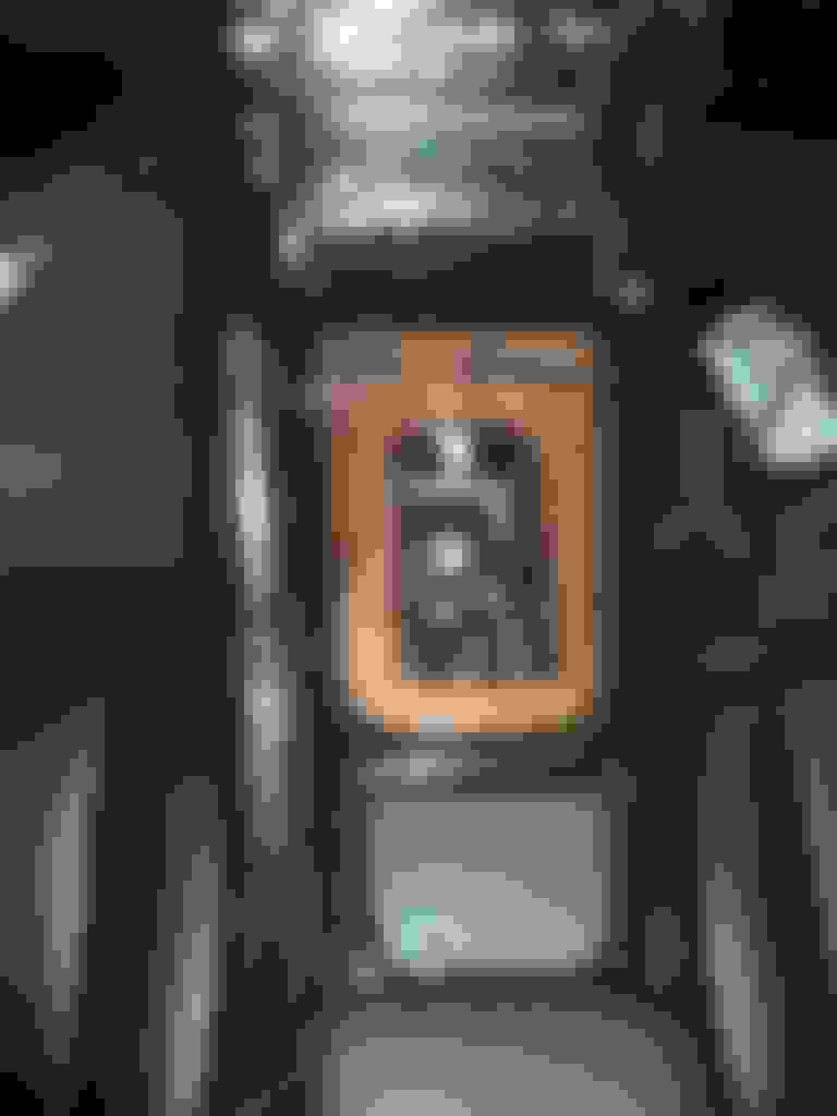
Interior all back together, and this is how the shifter sits. Low and left. I was hoping it would be a bit more centered. I figured it might be a little low, but off center caught me off guard
First gear:
But that about gets it all together. I will just have to at some point pull that shifter out and have the BRZ shifter welded on, and get a piece of angle iron to put on the shifter housing to act as the stop for the reverse lockout. I would also like to think up of something to actually retain the shifter end pivot ball in the little plastic bushing that I JB welded to the linkage part. If I can come up with something to do that, then I can remove the springs that are up in the shifter. I cut about 1 coil off of the springs that are inside the shifter to relieve some tension, but it's still not as smooth and pleasant to shift as I would like. Then, would like to get the Dakota digital box wired into ABS sensor for my speedo.
EDIT: The reason for the shifter being off center to the left is because of the adapter that I got from Collins. I was sent an adapter that had the cd009 mounting holes rotated a bit with respect to the JZ mounting holes. Almost as if it was off in the manufacturing process. This is the reason why those holes were close to breaking through in the above posts. I talked to Brett Collins about it, and he offered an exchange which I declined at the moment because I'm not pulling this thing out again. He offered a discounted rate on a new adapter to stash away for the next time I service this trans, which is hopefully never, or for the time when I finally get sick of looking at the off center shifter. I have to think about it though, considering the wasted cost that I will incur.
Picked up my trans from the freight carrier last night:
It is the CD009 from a 2006 350z with 62k miles on it. It is the kind with the shift fork and external slave, not the kind with the internal concentric slave. The shift fork in the 05-06 trans have the upgraded cast shift fork. It has the CD0 #2 cast in the casing and AZQ CD009 label on it. These signify the latest revision of the cd009. It shifts like butter through all gears:
Also, got my pedal set and rear main seal, which I will be doing while I am in there:
Thank you for taking the time to document this as you go, much appreciated. I know I am considering this swap to get rid of my auto tranny on my 1.5J single swap.
This will be a KILLER guide when it's done. I have an auto 1JZ going into my SC400 as well and will tackle this later, SUB'd..
Originally Posted by BiGEZ
Thank you for taking the time to document this as you go, much appreciated. I know I am considering this swap to get rid of my auto tranny on my 1.5J single swap.
No problem guys, and thanks. I have to give much credit to estomax and Halon, as they are one of the first, if not the first, couple people to do the swap here on CL and have sort of blazed the trail for others including myself to have a reference and the confidence to do the swap
Here is a link to a document created by estomax highlighting details from his install (Marko, hopefully you don't mind me linking this )
We will not need to be doing any bellhousing milling, since the newer kits have added the extra meat onto the flywheel.. Also, as far as I know (and will confirm when my Collins kit gets ordered and arrives), the Collins kit no longer requires a nut to be welded in a through hole for the starter bolts. Instead, the holes are threaded and studs are supplied to be loctite'd in place and starter fastened with nuts. Again, I will confirm this. I'm just saying it already now because Brett Collins told me that in my email communications with him.
Last edited by LoveSCs; 02-07-16 at 01:12 PM.
Reason: fixed link
I just ordered my kit from Collins. Hopefully will get it soon. I imagine most things should be in stock, except maybe the driveshaft
I did end up going with the kit listed in post 1 which includes an ACT 6 puck clutch kit good for 670 ft lb (crank I think...), trans mount, aluminum driveshaft, and of course adapter plate and flywheel with all hardware necessary to mount
Just bought an LS430 rear diff, which apparently bolts right up into the SC. It has the 3.266 gear ratio, which is more friendly for the 6 speed gearing. Otherwise, gearing would be way too short.
According to crawlpedia RPM calculator, cruising at 60mph in 6th gear (.794 ratio) on the 3.266 diff, the engine RPM should be about 1936, as opposed to 2324 on the 3.92 diff. This would help on MPG. I was considering just keeping the 3.92 diff in, since it will help the 1JZ feel a bit more torquey. I will see how it feels and if I get sick of changing gears all the time. I got a good deal on the LS diff, so figured might as well.
For those that are wondering, the gear ratios of the cd009 are as follows:
So, I have just come across something pretty disheartening, and something very relevant to this swap if you are using a high power single clutch kit. I don't know why I hadn't come across it while I was doing my research. Apparently, when upgrading to a stronger pressure plate, and predominantly with single disc kits, you are subjecting your JZ to what is called crankwalk.
For those of you that do not know what crankwalk is, it is when your crankshaft begins to develop play and movement in the front and rear directions. Mostly caused by the extra pressure exerted on the flywheel (and hence crankshaft) of the heavy duty pressure plates used in high power single disc clutch kits. ACT seems to have the worst reputation for causing crankwalk. And that's what Collins supplies with his kits....
Overtime, crankwalk can develop if the crank thrust washers begin to wear down. They wear down, again, from the extra pressure exerted on them from the pressure plate. This pressure is present when the clutch pedal is pressed. The harshest event on the thrust washers is a cold start with the pedal depressed. At this point, all oil has fallen off of the crank, and when the clutch is pressed, it forces the crank against the thrust washer (metal on metal), and then when the crank is forced to rotate while starting, it wears the thrust washer away little by little. Also, it's not good to keep the clutch pedal down at red lights. So, basically avoid using the clutch unless absolutely necessary, and jumper the clutch start switch so that the clutch does not need to be depressed while starting. You can also raise the idle a little bit to make sure that the thrust washers are getting adequate oil when you depress the clutch at stop lights to take off.
Over time, as crankwalk gets more severe, the thrust washers will eventually just drop from their installed location and into the oil pan, and will most likely go for a little ride around your block The crank will then have much more movement, and the connecting rods will not be firing straight, and will bind. Basically, you need a new short block... If you're lucky, the thrust washers stay in one piece without shredding and allowing little pieces to make their way up to the head...
Multi disc clutches do not contribute much to crankwalk because the pressure plates used are not of such a high clamping capacity. Multi disc clutches add more friction to the setup by using multiple discs against each other. This way, the pressure plate does not to be as strong. Only problem is, the only known multi disc kit for this swap is the SPEC kit, and used with Maverick adapter. SPEC is not the best brand of clutches...
I'm pretty upset because had I known this, I would've just stayed auto and got it built... Now I am too vested in this CD009 swap so there is no turning back for me. I am just going to have to keep an eye on the crank and make sure it is not walking. You can do this with a friend and a dial indicator. Setup the dial indicator on the crank pulley (not running lol) and have a friend depress the clutch and measure the movement.
If I start to notice any extra movement, I will start my 1.5JZ build. Hopefully that build doesn't happen until I want it to... By then, hopefully there are more multi disc kits to choose from..
If I had to start this from scratch again, I would probably go with the Maverick adapter and the SPEC twin disc kit...
 01-30-16, 07:46 PM


 )
)
 We'll see when the Loctite cures how the nut comes off: