Low Budget DIY Solution for Burnt Out Needles
 05-18-06, 07:54 AM
#1
Lexucanafer
Thread Starter
Below is an inexpensive and easy to perform ten step method for replacing the burnt out LEDs that illuminate(d) the gauge needles in the second generation (92-96) Lexus ES300. This is an all too common problem with these cars. When I bought my ES, two of the four gauge needles had already burnt out and the remaining two soon started to "flicker" which indicated that they too would inevitably die. I thought maybe I could purchase new needles from Lexus, but learned that this would not be possible. Buying a whole new cluster was possible, but at a very high price. So, there were five main factors influencing my decision to try to come up with a more practical solution to this problem:
1) Price:
It cost me a few dollars for the parts to do this repair, as opposed to paying a specialty repair shop a lot of money to fix the needles for me.
2) Time:
This repair can easily be completed in a matter of hours, as opposed to being without the cluster for 2 weeks (or longer) while it is sent off to be repaired.
3) Risks:
During the time it takes to do this DIY repair, the cluster does not go anywhere. This eliminates the possibility of serious damage being done to it were it in the hands of others - i.e. being dropped and damaged beyond repair or perhaps lost while in transit.
4) Ease of Repair:
This DIY project can be completed with a minimal amount of parts, tools, skills, money, and time.
This is not a very complicated project. It requires some concentration and common sense more than it does serious technical know-how.
5) Overall Benefits:
I've researched a number of alternative methods for dealing with the 2nd generation ES's notorious burnt out gauge needle problem, but no other method of which I am aware comes close to matching this fix when all the factors are considered - i.e. the minimal costs involved; the short length of time it takes to complete the project; the ease with which the repair can be implimented, and how visually pleasing and functionally effective the results are.
DISCLAIMER: Having stated that, I will not accept any responsibility for damages occurring as a result of this write-up. I have endeavoured to state the information below as clearly as possible, and I believe that if the process is followed correctly, good results can be achieved. However, should you decide to undertake this project yourself, you must assume full responsibility for any mishaps that might occur. I am sure you understand...
First Generation SC and GS owners:
This DIY write-up will work for your dead needles as well, but GS owners please note: the polarity of the needles (positive and negative contacts) is reversed in the 1Gen GS. (Thanks to Ghosryder5 for providing this information).
Tools and equipment:
Smallest size flathead “precision” screwdriver
Fine pointed tweezers
Scotch tape or masking tape
Soldering iron with fine pointed tip
Fine gauge solder wire
9 volt battery (for testing your LED circuit)
1K ohm 1/4 watt thru-hole resistor (for testing LED polarity)
A large piece of cardboard for work surface (you don't want to burn a hole in your kitchen table!)
A fast curing adhesive such as Super-Glue or 5 minute epoxy
Wire cutters
Wire strippers
Needle nose pliers
Black permanent ink felt marker
Magnifier (optional) - depending on how good your eyesight is, you might want to have some means of magnification at hand - i.e. a simple magnifying glass, a magnified workbench lamp, a microscope, a jeweller's loupe, etc. The LEDs are tiny and unless your eyesight is excellent, magnification of some sort is recommended for checking your work.
IMPORTANT SOLDERING INFO: If you want to attempt this project but have never soldered before, watch this:
video about hand soldering
The most important soldering tutorial elements to remember:
1) Keep tip of soldering iron clean. Have a small wet sponge handy.
2) Heat up solder joint first for a second or two, then touch the solder wire to both the solder tip and the joint being soldered.
3) Use enough heat so the solder melts quickly but doesn't overheat the joint.
4) Less is more - use enough solder to make a solid connection but don't overdo it.
5) A smooth shiny solder joint is a good solder joint. A dull grey solder joint is bad !
All it takes is a bit of soldering practice to be able to do it well.
Project Parts:
Wire wrapping wire (fine gauge [26 to 30 AWG] – about 2” length or less per needle)
330 ohm 1/4 watt thru-hole resistor (two per needle)
Red surface mount (SMD) LED - 1206 or 0805 package (one per needle)
These can be obtained at an electronic components supplier such as www.digikey.com, www.mouser.com, or on e-bay, or elsewhere.
Total cost for parts = $2 to $3 to repair four needles.
IMPORTANT TIP: Before removing the cluster, note how much fuel the fuel gauge is reading so you can reset the needle to exactly the same spot when it goes back onto the gauge.
Check out my other DIY write-up for removing the cluster from the car and also replacing the backlighting bulbs.
Step 1: Removing needles from cluster (after the cluster is out of the car and the tinted plastic front window has been removed)
IMPORTANT TIP: Note which needle came from which gauge as you remove them, they are not identical to each other. Example - the fuel gauge needle has a small metal counter-weight on the underside which the temperature gauge needle does not have.
I removed the needles from the cluster by very gently but firmly pulling them off with my fingers - I found some were easier to remove than others for unknown reasons.
I grasped the needle between thumb and forefinger, just where the lighter colored center strip ends at the base (wide area). That is the point at which the needle plugs into the gauge.
Step 2: Removing old needle LED strip
I removed the burnt out strip of LEDs in each needle using the small precision flathead screwdriver to carefully pry the strip up and out along the narrow length of the needle. It is held in place by tiny little ridges along the inside edge of the needle. When lifting the old LED strip, be careful not to damage the area where it attaches to the base of the needle. The base must remain intact and undamaged as it is how the needle attaches to the gauge. The whole needle, with the exception of the two metal contacts on either side of the center post is made of plastic, so be careful when working with it. It can be easily cracked, broken, or melted with the soldering iron. Cut the old LED strip from the base with the wire cutters. Most likely there will be a bit of the old strip left in the needle that you can't remove without potentially damaging the base, but that's ok. Just remove as much as you can and tidy it up by snipping off any bits of the wire that connected the old LED strip to the metal contact clips. Once you've done this with all the needles, you are ready to prepare the new little LED circuit that will go inside each needle.
Step 3: Identifying LED polarity and soldering wire to LED
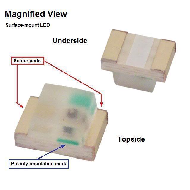
There are two large and two small needles so you will need different lengths of wire wrapping wire for each size needle. Just measure what you will need for the needle you are about to work on. You just need one piece of wire for each needle. It will connect from the negative (-) or "cathode" terminal of the new LED to the negative metal contact at the base of the needle. See image of needle indicating which contact is positive and which is negative. The LED should have a mark on it to identify which is the "anode" or positive (+) terminal or the "cathode" or negative (-) teminal. Where the mark is depends on the manufacturer. The four red LEDs I used are made by Lite-On Inc. - P/N: LTST-C170CKT (see photo below). I purchased them from www.digikey.com - Digikey part number: 160-1176-1-ND. This type has a tiny green mark on one end which indicates the "anode" (+) terminal. If you cannot determine the correct polarity of the LED, solder one end of a 1K ohm resistor to the positive post of a 9 volt battery and a piece of wire to the negative post. Then lay the battery on its side and touch the free end of the resistor to one end of the LED and the free end of the wire to the other end of the LED. If the LED lights up, the end that is making contact with the resistor is the "anode" (+) terminal. If it doesn't light up, turn the LED around and try again. Once you have determined the polarity of the LED, and have measured, cut and stripped the insolation off both ends of a piece of wire wrapping wire, you need to solder one end of the wire to the cathode (-) end of the LED. To do this, I stabilized the LED so it couldn't move while I soldered the wire to it. I grasped the LED at the anode (+) end with the tweezers and wrapped a small piece of scotch tape around the tweezers so it firmly held the LED and I could then let go of the tweezers. Then I "tinned" the cathode end of the LED with a tiny bit of solder, and also tinned one end of the wire. Now I touched the tinned end of the wire to the tinned end of the LED and touched the hot solder iron tip to the connection (for just a second) to solder the wire to the LED. Now the LED can be freed from the tweezer's grip as it is solidly attached to the wire. The next step is to attach two 330 ohm resistors in series to the other end of the LED - the "anode" (+) terminal.
Surface-mount LED:
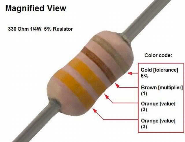
330 Ohm Resistor:
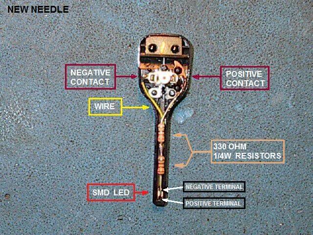
The "New" Temperature Gauge Needle (showing how the new little LED circuit fits inside it)
Step 4: Preparing the resistors
Take two 330 ohm resistors (purchased at www.digikey.com - Part Number: P330BACT-ND) and cut one of the leads off each of them leaving about 1/8th of an inch of lead on one side of each resistor. Leave the other leads full length. It doesn't matter which end of the resistor is cut. You want to solder the two short leads together so you have the two resistors connected to each other in series. Tin both short leads with solder and then position them so they are touching and heat the joint with the solder iron tip. Make sure the solder joint is solid. A good solder joint will look shiny not dull. Add a little more solder to the joint if necessary.
Step 5: Soldering resistors to LED
You will need to stabilize the LED (and wire) so you can solder to it without it moving on you so use a piece of tape to secure the wire with the LED to your work surface. The underside of the LED should face up. This is the side with the solder pads. Now you will need to measure the proper length of the resistor lead that you will solder to the LED. To do this use your needle as a measuring guide. The two joined resistors will be attached from one of the horizontal metal tabs at the base of the needle to the tip of the needle. The "bodies" of the two resistors should be at about the center point between needle base and tip. Trim off any extra length of resistor lead that will be attached to the LED. At this point don't trim any length from the resistor lead that will attach to the needle base...that's for later. Now you need to make a 90 degree bend at the very end of the resistor lead. the bend should be no more than about one millimeter in length. It is this bent tip of the resistor lead that you will solder to the anode (+) solder pad of the LED. You want to solder the two joined resistors to the LED so that they are parallel to the wire that is also soldered to the LED. This means that you will have (when finished) the LED at the tip of the needle with the wire and joined resistors running parallel up to the base of the needle. With the wire with LED attached taped to the work surface, tin the LED solder pad to which you will attach the resistor lead. Also tin the little bent end of the resistor lead. Now carefully position the resistor lead so the 1 millimeter bent tip touches the LED's (+) pad and the resistors run parallel with the wire. Touch the hot solder iron to the joint (for no more than a second) so that the resistor lead is soldered securely to the LED. Now you can check to see that when the wire, resistors, and LED are put inside the needle, everything fits well and does not extend above the open back of the needle, and that the LED is laying flat inside the needle tip with the face of the LED towards the face of the needle. Also, it is important that the resistor lead only touches the LED at the point at which it is soldered to it. It must NOT touch the LED anywhere else. This is the reason for the tiny bend in the resistor lead so that the rest of the lead is above the LED surface and not laying right against it when the lead and the LED are attached to each other. Some adjustments may be needed to get a good fit.
Step 6: Soldering resistor lead and wire to positive and negative contacts
It's a good idea to test your little circuit before attaching it to the needle so, using your 9v battery again (without the 1k resistor attached) touch the end of the wire to the negative (-) battery post and the end of the 330 ohm resistor lead to the positive (+) battery post and see that the LED lights up.
Now that you have everything working and ready to fit inside the needle, it is time to solder your little LED circuit into place. But first, you should trim off any excess resistor lead and wire. Position everything into the needle as it should look when done and run the wire up along the inside edge of one side of the needle to the horizontal metal (-) tab and do the same with the resistor lead up to the other horizontal metal (+) tab. You should have extra lengths of both wire and resistor lead so make sure everything is in the proper position and then trim off the extra lengths. But be careful not to trim too much. You can always trim more but once it's cut , it's CUT!
Now you can solder everything into place inside the needle. So, tin the horizontal metal tabs at the base of the needle and tin both the trimmed resistor lead and the stripped wire. Now, hold the wire to the negative (-) metal tab and *carefully* touch the hot solder tip to it. Don't melt anything! Now do the same with the resistor lead on the positive (+) metal needle tab. Now just to be sure, solder a 3" piece of wire to each of the 9 volt battery terminals and touch the positive wire to the positive contact on the needle and the negative wire to the negative contact on the needle and watch the LED at the tip of the needle light up.
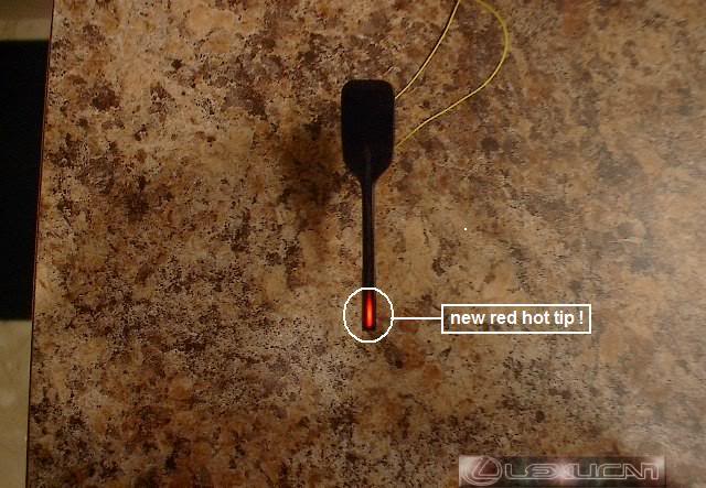
The "New" <RED TIPPED Speedometer Needle (hooked up to a 9V battery to test it)
Step 7: Securing your LED circuit inside the needle
So, now you are ready to glue everything inside the needle. I used a tiny drop of Super glue to secure the body of one of the resistors to the inside of the needle. You could also use some fast drying epoxy. Don't use too much of whatever type of adhesive you use. It only takes a tiny bit to secure everything well, if it is laying properly inside the needle. Remember that you don't want wires or anything poking up above the open surface of the needle or it could restrict the free movement of the needle when re-attached to the gauge. Neatness counts!
Step 8: Repeating the process for the rest of the needles
Once you have one done, the next three will go quicker, because now you are an expert !
Step 9: Blackening out the front face of the needles
Since only the tips of the needles are illuminated now, I used a black felt permanent ink marker to blacken out all but about a 1/4" to 1/2" section of the opaque lighter colored plastic strip running up the center of each needle. Don't blacken right to the tip as the light from the new LED has to be able to glow through. **This step does not make any difference to the function of your new needles, but esthetically speaking, the needles will look less "altered" after the center strips are blacked out and are no longer noticeable through the smoked plastic cluster window.**
Step 10: Re-attaching the new needles to gauges
For this part of the process, I had the instrument cluster back in the car and reconnected. To re-attach each needle, carefully and gently push it onto the face of the gauge, making sure the two metal contacts on the needle line up properly on the tiny posts on the gauge face. Once the needles are back on, start the car and check that they all light up and are reading correctly. Then you can re-attach the tinted plastic front window and complete the rest of the cluster reinstall.
***************************
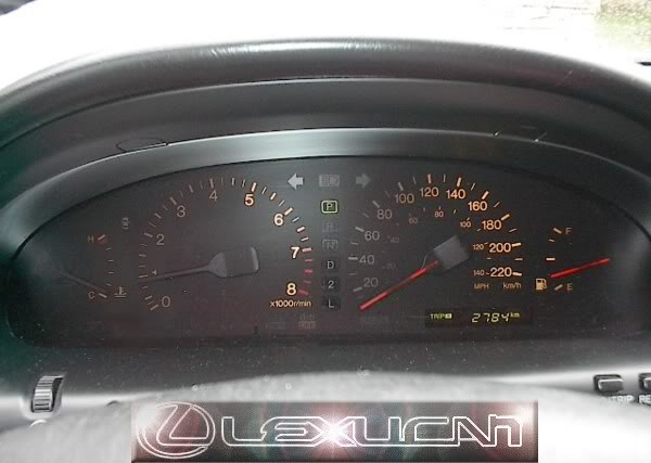
So, now it's time to compare. The first photo below is of the cluster before the project work began. Notice that the temperature gauge and tachometer gauge needles are completely burnt out and the speedometer and fuel gauge needles are on their way out (flickering). Also note that the cluster backlighting is dim in many areas due to burnt out incandescent bulbs behind the gauges.
THE "OLD" CLUSTER (which clearly has seen better days!)
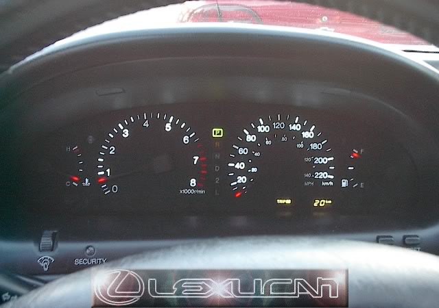
AND NOW FOR THE "RESULTS" PHOTOS:
DAYLIGHT (the gauges are clearly readable in the daytime even though you can barely see the non-illuminated part of the needles)
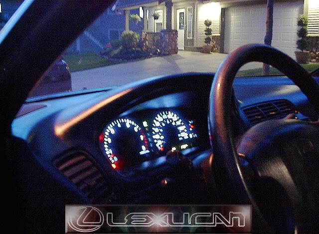
AT NIGHT (the needles are totally invisible except for the brightly lit <RED TIPS!)

COOL NEW BACKLIGHTING! (the new utrabright white LEDs behind the gauges make the cluster really POP at night!)
1) Price:
It cost me a few dollars for the parts to do this repair, as opposed to paying a specialty repair shop a lot of money to fix the needles for me.
2) Time:
This repair can easily be completed in a matter of hours, as opposed to being without the cluster for 2 weeks (or longer) while it is sent off to be repaired.
3) Risks:
During the time it takes to do this DIY repair, the cluster does not go anywhere. This eliminates the possibility of serious damage being done to it were it in the hands of others - i.e. being dropped and damaged beyond repair or perhaps lost while in transit.
4) Ease of Repair:
This DIY project can be completed with a minimal amount of parts, tools, skills, money, and time.
This is not a very complicated project. It requires some concentration and common sense more than it does serious technical know-how.
5) Overall Benefits:
I've researched a number of alternative methods for dealing with the 2nd generation ES's notorious burnt out gauge needle problem, but no other method of which I am aware comes close to matching this fix when all the factors are considered - i.e. the minimal costs involved; the short length of time it takes to complete the project; the ease with which the repair can be implimented, and how visually pleasing and functionally effective the results are.
DISCLAIMER: Having stated that, I will not accept any responsibility for damages occurring as a result of this write-up. I have endeavoured to state the information below as clearly as possible, and I believe that if the process is followed correctly, good results can be achieved. However, should you decide to undertake this project yourself, you must assume full responsibility for any mishaps that might occur. I am sure you understand...
First Generation SC and GS owners:
This DIY write-up will work for your dead needles as well, but GS owners please note: the polarity of the needles (positive and negative contacts) is reversed in the 1Gen GS. (Thanks to Ghosryder5 for providing this information).
Tools and equipment:
Smallest size flathead “precision” screwdriver
Fine pointed tweezers
Scotch tape or masking tape
Soldering iron with fine pointed tip
Fine gauge solder wire
9 volt battery (for testing your LED circuit)
1K ohm 1/4 watt thru-hole resistor (for testing LED polarity)
A large piece of cardboard for work surface (you don't want to burn a hole in your kitchen table!)
A fast curing adhesive such as Super-Glue or 5 minute epoxy
Wire cutters
Wire strippers
Needle nose pliers
Black permanent ink felt marker
Magnifier (optional) - depending on how good your eyesight is, you might want to have some means of magnification at hand - i.e. a simple magnifying glass, a magnified workbench lamp, a microscope, a jeweller's loupe, etc. The LEDs are tiny and unless your eyesight is excellent, magnification of some sort is recommended for checking your work.
IMPORTANT SOLDERING INFO: If you want to attempt this project but have never soldered before, watch this:
The most important soldering tutorial elements to remember:
1) Keep tip of soldering iron clean. Have a small wet sponge handy.
2) Heat up solder joint first for a second or two, then touch the solder wire to both the solder tip and the joint being soldered.
3) Use enough heat so the solder melts quickly but doesn't overheat the joint.
4) Less is more - use enough solder to make a solid connection but don't overdo it.
5) A smooth shiny solder joint is a good solder joint. A dull grey solder joint is bad !
All it takes is a bit of soldering practice to be able to do it well.
Project Parts:
Wire wrapping wire (fine gauge [26 to 30 AWG] – about 2” length or less per needle)
330 ohm 1/4 watt thru-hole resistor (two per needle)
Red surface mount (SMD) LED - 1206 or 0805 package (one per needle)
These can be obtained at an electronic components supplier such as www.digikey.com, www.mouser.com, or on e-bay, or elsewhere.
Total cost for parts = $2 to $3 to repair four needles.
IMPORTANT TIP: Before removing the cluster, note how much fuel the fuel gauge is reading so you can reset the needle to exactly the same spot when it goes back onto the gauge.
Check out my other DIY write-up for removing the cluster from the car and also replacing the backlighting bulbs.
Step 1: Removing needles from cluster (after the cluster is out of the car and the tinted plastic front window has been removed)
IMPORTANT TIP: Note which needle came from which gauge as you remove them, they are not identical to each other. Example - the fuel gauge needle has a small metal counter-weight on the underside which the temperature gauge needle does not have.
I removed the needles from the cluster by very gently but firmly pulling them off with my fingers - I found some were easier to remove than others for unknown reasons.
I grasped the needle between thumb and forefinger, just where the lighter colored center strip ends at the base (wide area). That is the point at which the needle plugs into the gauge.
Step 2: Removing old needle LED strip
I removed the burnt out strip of LEDs in each needle using the small precision flathead screwdriver to carefully pry the strip up and out along the narrow length of the needle. It is held in place by tiny little ridges along the inside edge of the needle. When lifting the old LED strip, be careful not to damage the area where it attaches to the base of the needle. The base must remain intact and undamaged as it is how the needle attaches to the gauge. The whole needle, with the exception of the two metal contacts on either side of the center post is made of plastic, so be careful when working with it. It can be easily cracked, broken, or melted with the soldering iron. Cut the old LED strip from the base with the wire cutters. Most likely there will be a bit of the old strip left in the needle that you can't remove without potentially damaging the base, but that's ok. Just remove as much as you can and tidy it up by snipping off any bits of the wire that connected the old LED strip to the metal contact clips. Once you've done this with all the needles, you are ready to prepare the new little LED circuit that will go inside each needle.
Step 3: Identifying LED polarity and soldering wire to LED
There are two large and two small needles so you will need different lengths of wire wrapping wire for each size needle. Just measure what you will need for the needle you are about to work on. You just need one piece of wire for each needle. It will connect from the negative (-) or "cathode" terminal of the new LED to the negative metal contact at the base of the needle. See image of needle indicating which contact is positive and which is negative. The LED should have a mark on it to identify which is the "anode" or positive (+) terminal or the "cathode" or negative (-) teminal. Where the mark is depends on the manufacturer. The four red LEDs I used are made by Lite-On Inc. - P/N: LTST-C170CKT (see photo below). I purchased them from www.digikey.com - Digikey part number: 160-1176-1-ND. This type has a tiny green mark on one end which indicates the "anode" (+) terminal. If you cannot determine the correct polarity of the LED, solder one end of a 1K ohm resistor to the positive post of a 9 volt battery and a piece of wire to the negative post. Then lay the battery on its side and touch the free end of the resistor to one end of the LED and the free end of the wire to the other end of the LED. If the LED lights up, the end that is making contact with the resistor is the "anode" (+) terminal. If it doesn't light up, turn the LED around and try again. Once you have determined the polarity of the LED, and have measured, cut and stripped the insolation off both ends of a piece of wire wrapping wire, you need to solder one end of the wire to the cathode (-) end of the LED. To do this, I stabilized the LED so it couldn't move while I soldered the wire to it. I grasped the LED at the anode (+) end with the tweezers and wrapped a small piece of scotch tape around the tweezers so it firmly held the LED and I could then let go of the tweezers. Then I "tinned" the cathode end of the LED with a tiny bit of solder, and also tinned one end of the wire. Now I touched the tinned end of the wire to the tinned end of the LED and touched the hot solder iron tip to the connection (for just a second) to solder the wire to the LED. Now the LED can be freed from the tweezer's grip as it is solidly attached to the wire. The next step is to attach two 330 ohm resistors in series to the other end of the LED - the "anode" (+) terminal.
Surface-mount LED:
330 Ohm Resistor:
The "New" Temperature Gauge Needle (showing how the new little LED circuit fits inside it)
Step 4: Preparing the resistors
Take two 330 ohm resistors (purchased at www.digikey.com - Part Number: P330BACT-ND) and cut one of the leads off each of them leaving about 1/8th of an inch of lead on one side of each resistor. Leave the other leads full length. It doesn't matter which end of the resistor is cut. You want to solder the two short leads together so you have the two resistors connected to each other in series. Tin both short leads with solder and then position them so they are touching and heat the joint with the solder iron tip. Make sure the solder joint is solid. A good solder joint will look shiny not dull. Add a little more solder to the joint if necessary.
Step 5: Soldering resistors to LED
You will need to stabilize the LED (and wire) so you can solder to it without it moving on you so use a piece of tape to secure the wire with the LED to your work surface. The underside of the LED should face up. This is the side with the solder pads. Now you will need to measure the proper length of the resistor lead that you will solder to the LED. To do this use your needle as a measuring guide. The two joined resistors will be attached from one of the horizontal metal tabs at the base of the needle to the tip of the needle. The "bodies" of the two resistors should be at about the center point between needle base and tip. Trim off any extra length of resistor lead that will be attached to the LED. At this point don't trim any length from the resistor lead that will attach to the needle base...that's for later. Now you need to make a 90 degree bend at the very end of the resistor lead. the bend should be no more than about one millimeter in length. It is this bent tip of the resistor lead that you will solder to the anode (+) solder pad of the LED. You want to solder the two joined resistors to the LED so that they are parallel to the wire that is also soldered to the LED. This means that you will have (when finished) the LED at the tip of the needle with the wire and joined resistors running parallel up to the base of the needle. With the wire with LED attached taped to the work surface, tin the LED solder pad to which you will attach the resistor lead. Also tin the little bent end of the resistor lead. Now carefully position the resistor lead so the 1 millimeter bent tip touches the LED's (+) pad and the resistors run parallel with the wire. Touch the hot solder iron to the joint (for no more than a second) so that the resistor lead is soldered securely to the LED. Now you can check to see that when the wire, resistors, and LED are put inside the needle, everything fits well and does not extend above the open back of the needle, and that the LED is laying flat inside the needle tip with the face of the LED towards the face of the needle. Also, it is important that the resistor lead only touches the LED at the point at which it is soldered to it. It must NOT touch the LED anywhere else. This is the reason for the tiny bend in the resistor lead so that the rest of the lead is above the LED surface and not laying right against it when the lead and the LED are attached to each other. Some adjustments may be needed to get a good fit.
Step 6: Soldering resistor lead and wire to positive and negative contacts
It's a good idea to test your little circuit before attaching it to the needle so, using your 9v battery again (without the 1k resistor attached) touch the end of the wire to the negative (-) battery post and the end of the 330 ohm resistor lead to the positive (+) battery post and see that the LED lights up.
Now that you have everything working and ready to fit inside the needle, it is time to solder your little LED circuit into place. But first, you should trim off any excess resistor lead and wire. Position everything into the needle as it should look when done and run the wire up along the inside edge of one side of the needle to the horizontal metal (-) tab and do the same with the resistor lead up to the other horizontal metal (+) tab. You should have extra lengths of both wire and resistor lead so make sure everything is in the proper position and then trim off the extra lengths. But be careful not to trim too much. You can always trim more but once it's cut , it's CUT!
Now you can solder everything into place inside the needle. So, tin the horizontal metal tabs at the base of the needle and tin both the trimmed resistor lead and the stripped wire. Now, hold the wire to the negative (-) metal tab and *carefully* touch the hot solder tip to it. Don't melt anything! Now do the same with the resistor lead on the positive (+) metal needle tab. Now just to be sure, solder a 3" piece of wire to each of the 9 volt battery terminals and touch the positive wire to the positive contact on the needle and the negative wire to the negative contact on the needle and watch the LED at the tip of the needle light up.
The "New" <RED TIPPED Speedometer Needle (hooked up to a 9V battery to test it)
Step 7: Securing your LED circuit inside the needle
So, now you are ready to glue everything inside the needle. I used a tiny drop of Super glue to secure the body of one of the resistors to the inside of the needle. You could also use some fast drying epoxy. Don't use too much of whatever type of adhesive you use. It only takes a tiny bit to secure everything well, if it is laying properly inside the needle. Remember that you don't want wires or anything poking up above the open surface of the needle or it could restrict the free movement of the needle when re-attached to the gauge. Neatness counts!
Step 8: Repeating the process for the rest of the needles
Once you have one done, the next three will go quicker, because now you are an expert !
Step 9: Blackening out the front face of the needles
Since only the tips of the needles are illuminated now, I used a black felt permanent ink marker to blacken out all but about a 1/4" to 1/2" section of the opaque lighter colored plastic strip running up the center of each needle. Don't blacken right to the tip as the light from the new LED has to be able to glow through. **This step does not make any difference to the function of your new needles, but esthetically speaking, the needles will look less "altered" after the center strips are blacked out and are no longer noticeable through the smoked plastic cluster window.**
Step 10: Re-attaching the new needles to gauges
For this part of the process, I had the instrument cluster back in the car and reconnected. To re-attach each needle, carefully and gently push it onto the face of the gauge, making sure the two metal contacts on the needle line up properly on the tiny posts on the gauge face. Once the needles are back on, start the car and check that they all light up and are reading correctly. Then you can re-attach the tinted plastic front window and complete the rest of the cluster reinstall.
***************************
So, now it's time to compare. The first photo below is of the cluster before the project work began. Notice that the temperature gauge and tachometer gauge needles are completely burnt out and the speedometer and fuel gauge needles are on their way out (flickering). Also note that the cluster backlighting is dim in many areas due to burnt out incandescent bulbs behind the gauges.
THE "OLD" CLUSTER (which clearly has seen better days!)
AND NOW FOR THE "RESULTS" PHOTOS:
DAYLIGHT (the gauges are clearly readable in the daytime even though you can barely see the non-illuminated part of the needles)
AT NIGHT (the needles are totally invisible except for the brightly lit <RED TIPS!)
COOL NEW BACKLIGHTING! (the new utrabright white LEDs behind the gauges make the cluster really POP at night!)
Last edited by Lexucan; 05-31-12 at 08:14 AM. Reason: Added additional information
 05-18-06, 04:22 PM
#3
Driver School Candidate

Join Date: May 2006
Location: Oregon
Posts: 7
Likes: 0
Received 0 Likes
on
0 Posts
First of all, Great job!!
I am all thumbs when it comes down to electrical stuff like that.
I am all thumbs when it comes down to electrical stuff like that.
05-18-06, 05:27 PM
#4
Lexucanafer
Thread Starter
Thanks for the comments.
It sounds more difficult than it is.
It took a weekend afternoon and cost me next to nothing....not counting the refreshments!
It sounds more difficult than it is.
It took a weekend afternoon and cost me next to nothing....not counting the refreshments!
Last edited by Lexucan; 05-18-06 at 05:57 PM.
The following users liked this post:
DoubleLex (12-31-23)
05-18-06, 06:16 PM
#5
Rookie

Join Date: Mar 2006
Location: Florida
Posts: 79
Likes: 0
Received 0 Likes
on
0 Posts
Originally Posted by Lexucan
Thanks for the comments.
It sounds more difficult than it is.
It took a weekend afternoon and cost me next to nothing....not counting the refreshments!
It sounds more difficult than it is.
It took a weekend afternoon and cost me next to nothing....not counting the refreshments!
05-19-06, 07:28 AM
#6
Rookie
Join Date: Mar 2006
Location: Florida
Posts: 79
Likes: 0
Received 0 Likes
on
0 Posts
Originally Posted by Lexucan
Thanks for the comment.
But dude.....you mean to tell me that after I spent hours painstakingly putting together, perfecting, and posting detailed, step by step instructions so you could easily do it yourself, you'd rather I do it for you? Quite honestly, I don't think I want to be in the needle repair business. I did it to my own set to save some money and because I was curious about whether or not it was possible or feasable to do it myself. I'm very happy with the results so it was a worthwhile project, however, I think it is more of a DIY project than a "send me your needles" project.....sorry. But thanks for the vote of confidence.
I bet OLT is sighing with relief......LOL (j/k)
But dude.....you mean to tell me that after I spent hours painstakingly putting together, perfecting, and posting detailed, step by step instructions so you could easily do it yourself, you'd rather I do it for you?
Quite honestly, I don't think I want to be in the needle repair business. I did it to my own set to save some money and because I was curious about whether or not it was possible or feasable to do it myself. I'm very happy with the results so it was a worthwhile project, however, I think it is more of a DIY project than a "send me your needles" project.....sorry. But thanks for the vote of confidence. I bet OLT is sighing with relief......LOL (j/k)
05-19-06, 10:45 AM
#7
Lexus Fanatic
Nice work with those pesky gauge needles most of us have grown tired of  If you don't mind, I will link this thread with the ES300/330 DIY master thread. Once again, awesome job!
If you don't mind, I will link this thread with the ES300/330 DIY master thread. Once again, awesome job!
Trending Topics
 08-02-06, 12:40 AM
#9
Driver School Candidate

Join Date: Aug 2006
Location: CA
Posts: 1
Likes: 0
Received 0 Likes
on
0 Posts
Hey, I'm about to do this myself. Do remember the voltage drop across each needle? I'm not sure if it's possible, but I wanted to try to get the whole needle lit up by aiming a high output LED towards the tip from the base.
I think the voltage is different when the headlights are on and off, but if you can remember either, that would be awesome.
Thanks!
P.S. I PMed you as well
I think the voltage is different when the headlights are on and off, but if you can remember either, that would be awesome.
Thanks!
P.S. I PMed you as well
Last edited by bleirrot; 08-02-06 at 12:46 AM.
08-02-06, 05:27 PM
#10
Driver


Join Date: Apr 2006
Location: TX
Posts: 128
Likes: 0
Received 0 Likes
on
0 Posts
Hey guys, i would like to do this project but the thing is, the needles on my car are kind of ****ed up due to bad connection points. Do any of ya'll know somewhere or website where I can just purchase the whole LED needles (Engine Temperature, Speed needle, RPM needle, Fuel Gauge needle)? and also, the LED bulbs that make your gauge look oh so cool for your speedometer

 04-21-07, 09:59 PM
#15
Lexus Fanatic
I don't believe this mod can be done on an '02 ES since the cluster needles on that ES is designed under a different electroluminiscent technology than from a '92-'96 ES. In other words, the '02 needles are more updated and less problematic than the '92-'96 needles

