When you click on links to various merchants on this site and make a purchase, this can result in this site earning a commission. Affiliate programs and affiliations include, but are not limited to, the eBay Partner Network.
Unless anyone has any questions about the Nav display, I think I am going to begin tearing it down and converting it to a modern LCD. I can't really think of a good reason to keep the original navigation if I am installing a computer. That means my reverse engineering of it has pretty much ended with what I have already determined. Of course, since I will still have the functioning guts, I will still be able to play around with it if the desire comes up.
Originally, I was thinking that even after I swapped the LCD, I would get it to communicate with the ECU to keep the factory navigation, but the maps are seriously outdated and the DVD is already the latest that can be installed. Not being able to enter data while moving is also another negative for it.
There are some features I do like, for example the maintenance menu. But I can just duplicate that in software. It should have been more incorporated with OBD anyway.
I will be trying to keep the touchscreen part, however. I just need to learn how to interface it with a microcontroller.
On that note can anyone recommend a navigation software that doesn't suck? I haven't nailed down which OS I will be choosing yet. I have been leaning towards Android, but in some ways that is a pain to work with custom hardware and software.
I'll need to look it up also, but I assume you just used a flip-flop to toggle on the second push. It may become unneccesary once I finish this IEBus doohickey since I will be able to sense any button pushes over the AVC-LAN. Then I control something like that with software.
Yup.
I "broke" the switch out of the circuit and used it to toggle a double-pole relay. One side of the relay looped back into the circuit (to perform the original function of the switch). The other side was mine to use as I wished. Then used an off-the-shelf flip-flop board to convert the momentary press into an alt. action circuit.
I "broke" the switch out of the circuit and used it to toggle a double-pole relay. One side of the relay looped back into the circuit (to perform the original function of the switch). The other side was mine to use as I wished. Then used an off-the-shelf flip-flop board to convert the momentary press into an alt. action circuit.
Simple but elegant. My favorite kind of solutions.
This weekend will be dedicated to finishing up some of the interior mods I had started.
First up, I received the center console with the cup-holder to replace my broken one. It was filthy as all heck, so cleaned it all up and hit the black plastic with WD-40 (has an effect like amor-all, but shinier.) The ashtray portion was in worst shape than mine, so I borrowed a few parts from it and kept the bulk of my original. Just the cupholder alone was worth the $50, since I couldn't find a cupholder by itself for less than $99. Still to do: Redo the ashtray light and charger mod.
Speaking of the charger mod, I had a USB/Aux deal on order for a while and finally received it yesterday. It was huge and totally would not fit. So, please, don't order the Jenaux for this purpose. Almost twice the size of the cigarette lighter port. After some searching I found that the Nissan Juke has what I am actually looking for. So, I have it on order. For now, the center console is back in place waiting.
The next mod was to dig into the stereo. First, the display lens in my original head unit was all cloudy and you could barely see through it anymore from years of UV exposure. So, I picked up some UV resistant and anti-glare plexiglass and made a new window.
I then swapped out the 14 green lamps with blue LEDs. There are two illumination circuits in the stereo each at 8V and 80ma max. On one string is 8 lamps and the other has 6.
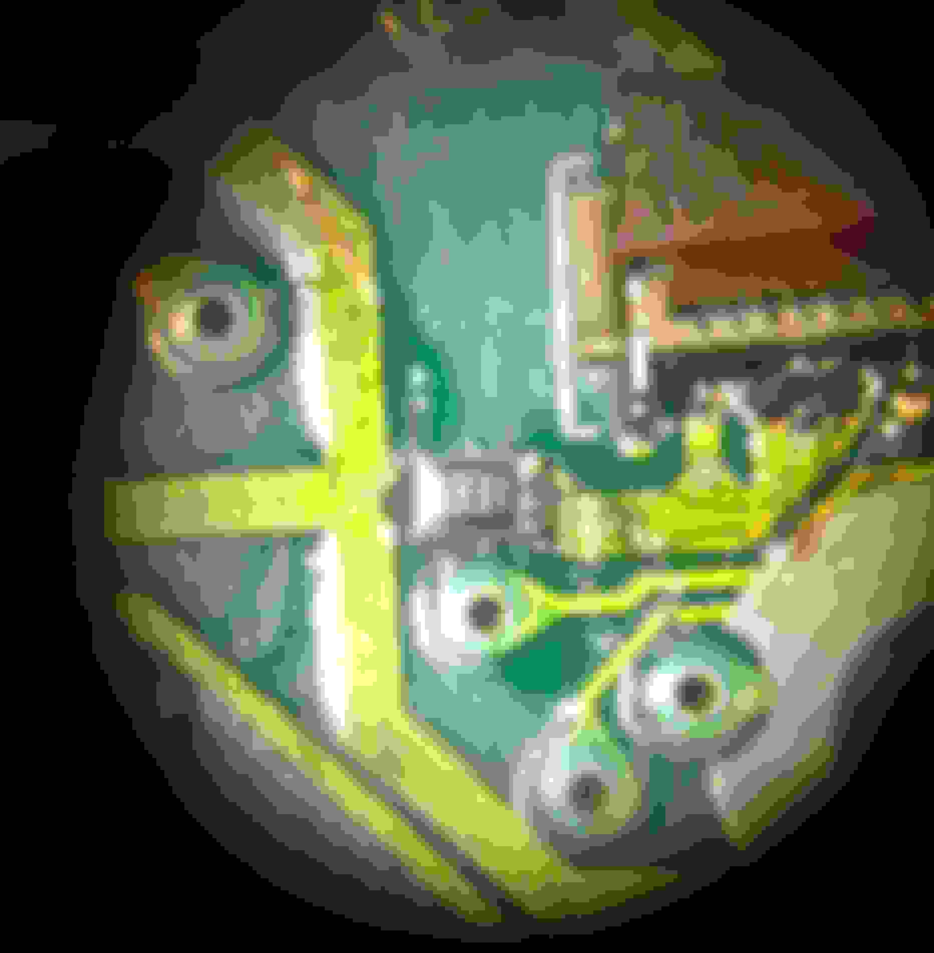
Unlike incandescent lamps, LEDs require a resistor or they will just keep drawing current until they burn up. The supply appears to have current limiting in it, but to be on the safe side, I cut the ground trace common to both strings and installed two 330ohm resistors in parallel (160 ohms.) On my bench supply, this ended up running about 30mA at 9V which the blue LEDs can handle, but it is pushing it near the limits. I would recommend using two 470 ohm resistors instead. The reason you need two is because the resistor are only quarter watt. You double whatever resistance you are looking for and put two in parallel and you end up with a half/watt. You could buy a 1/2 or full watt surface mount resistor and only use one if you like. I just used what I had on hand.
Two 330 Ohm resistors stacked. Cut and removed a piece of the trace and soldered this resistors across the cut.
My advice if you do this:
Do one LED at a time. Trust me on this. You will wire up at least one wrong if you try to hurry. For each LED, hold the plastic part in a pair of pliers and bend the leads as close to the plastic body as possible without stressing the part too much. The flat side of the LED goes away from the thick traces. Use 3mm LEDs. Trim the leads down to the little knee. Form the LEDs and drop them in place, soldering one at a time. Try your best to get them facing straight because you do not want to twist them around much once they are soldered or you might rip up a pad or break the lead.
Use 470 ohm resistors instead of the 330 I used. You can use a full size resistor, just scratch the green mask over the wires further apart than I did. And again, when aligning them after you are done, be careful not to move them much. If you need to move them a lot, unsolder that one and start over.
I do plan to go in there and replace the LCD backlight but didn't have the surface mount LEDs on hand.
For the next mod, I am not 100% certain will work with this LCD. I took polarizing film and rotated it until it blacked out the screen and then cut a piece the size of the window. What this should do is reverse the the LCD. Now the digits will be white instead of black and the background should be dark.
You won't be able to see the effect much until I reinstall it and light it up. I'll do that tomorrow.
I'm probably going to need to cut another window because it looks like that section of plexi had a scratch on it.
You will notice that you cannot see the black line that goes across the bottom anymore and the screen now looks paper white.
Excuse the scratched up TAPE button. That is an upcoming mod I don't want to disclose until I have it working. My first attempt was not all that successful. Hint: Bye-Bye tape deck.
I also swapped out the LEDs in the seat heater assembly, but didn't take a picture of it. That was pretty standard fare, though. Just remove existing 3mm LEDs and replace them.
Oh, and I found a map light assembly that has the microphone in it already for $60. Got that on its way.
More pics of the stereo running tomorrow (crossing fingers.)
So, trying to use the common ground point didn't work out so well. The 8 lamp circuit was nice and bright, but the 6 lamp circuit didn't even have enough power to light up.
So back to the schematics. It appears the 8 lamp circuit is always on when the dash illumination is on, but the 6 lamp circuit only comes on when the radio is turned on. So the six lamp circuit is controlled by a resistor which is limiting the current further.
So, no way around treating them as separate circuits, which means going after the positive side feeds.
So, I removed the 330 ohm stack and jumpered that trace again.
I then traced out the ILL1 and ILL2 lines to find their single point of sources (if you cut the wrong trace, you risk feeding full power into one of the LEDs.) You have to cut the trace before it goes to any of the LEDs.
Recalculating things... on the 8 lamp circuit, I want to draw about 10ma each. So I need to supply 80ma. A 100 ohm resistor works for that.
Using a 100 ohm for the 6 lamp circuit should give about 13ma per LED.
And this worked. But... the 6 lamp LEDs are still too dim for my tastes. I am going to have to wait until it is darker out to truly judge it, but I am probably going to need to use a smaller resistor for that circuit. It appears the transistor used to switch on that circuit is already limiting the current.
And because it is already bright out, it is hard for me to take a pic of it in action. So, I will post pics up later tonight.
The reversing of the LCD did not work out at all. It completely blanked out the LCD and you couldn't see anything. So I removed the polarizer for now until I can figure out how to do it.
EDIT: Well duh, you need to remove the original polarizing film first. http://www.600rr.net/vb/103-03-06-rr...rse-lcd-2.html
That is the effect I am looking for. I'll save this project for when I have the LEDs to redo the LCD backlight. I don't want to risk taking it out more than once.
Putting a computer in the car is not as simple as it might sound. You need to deal with a lot of special requirements for being in a car.
First, you need to think about power. How will you power it, how will it start up and shutdown with the ignition?
Regarding the screen. Will it operate in the cold or extreme heat? Can it be read when the sun is bright? Can the driver see it from his position?
Can the touchscreen be operated even with gloves?
What OS is right? It needs to be touch-friendly and it needs minimum interaction to boot and operate.
What features must it have? How about connectivity? If you will have wifi, how will you provide it? How will you protect the storage from vibration?
This was a WHOLE lot tougher years ago before android, decent tablets, cheap SolidState hard drives, etc...
So, I have on order a 7" 1280x800 IPS LCD. It is only 400 nit brightness, but without spending a fortune on a screen, that's about all there is. The brightness will need to be boosted. I plan to connect to the screen using HDMI with connections for a couple composite devices as well. It also has VGA in case I really want to connect it up to the stock navigation ECU. The VGA input supports composite sync as well. Finally, it has a reverse input if I want to add a rearview camera.
For the computer, I am really split between linux, android, and windows 8.1. Android is probably the best touchscreen OS, but it is also a pain to connect up to hardware and you will probably need to write most of your own apps since not much exists for for in-car use.
Thankfully, all of those OSes can run on an intel processor. So, I am going with an atom processor based computer which is fanless and low power. I am currently looking at the Ainol or Vensmile W10 mini PCs which are essentially tablets guts without the LCD. Intended for connecting to your TV. Both of these have internal batteries, which will help with the shut-down and startup and also surviving the cranking. They are also small enough to fit inside the nav display itself.
Having a battery in there is the key. Since the system has the ability to tell if it is plugged into AC power or not, we can use that to begin hibernation when you turn the ignition off. It can also stay running through the turning of the ignition and quick stops for gas. Getting it to power on automatically will still be a bit tricky, though. I may not have it power on automatically and instead re-use the open button. I do plan to have the door close automatically when the computer is shutting off. I am surprised that wasn't a built in feature.
The only connection available on these little PCs is USB, but nearly everything is USB nowadays anyway. Arduinos can provide extra I/O if needed.
I have settled on the necessities. I need decent navigation, bluetooth handsfree capability, the ability to play MP3s and other media, and a dash cam. I want voice control of as much of it as possible. I would like to duplicate (but improve) the maintenance function of the stock unit. I would like for it to remind me of things I need at the store when the GPS senses that I am at the store.
I would like a police scanner and other radio reception (can do this with SDR - software defined radio - using a little dongle.)
I want mobile wifi in the car that can allow me to get traffic and other information. I would like that wifi to be available to a passenger as well.
I would like a wireless display that the passenger can use on their lap to control the system.
I would like the system to be as integrated into the car system as much as possible. That means emulating the navigation system and phone system. I would like some things to be controllable from the steering wheel controls and the head unit controls.
There is definitely a lot to consider, but I tell you... it was much harder the last time I did this. We pretty much needed to install a full desktop in our cars back then.
But even though we have tiny PCs, super high-resolution screens, USB simplifying wiring, etc... Very few things are just perfect as they are.
The carPC is going to be a long project. I'll be breaking it up into smaller projects so I can hopefully document what I am doing and why I made certain decisions.
Most of this stuff is coming from China on a slow boat. So in the meantime, I will be finishing up the rest of the mods.
I pulled out the 100ohm resistor on the ILL2 circuit in the head-unit and replaced it with a 68ohm. It's certainly brighter, but I am just really surprised how much brighter the other circuit is. But 68 ohms is the lowest I am willing to go for safety. As I mentioned before, if one LED gives up the ghost, things will cascade quickly until it breaks the stereo. If you want to do this and be 200% safe, use a resistor for each LED and don't be lazy like me. I have the dash put back together, so I promise pictures tonight.
Probably going to be spending the evening reverse engineering the factory touchscreen. An IR touchscreen is the perfect type for a car. It will operate with gloves on and is not really affected by the temperature. I really would like to use it in my system.
Couldn't agree more on the CarPC strategy - small steps. Get Item #1 working before going on to Item #2. And, once Item #2 is working, go back and check the functionality of Item #1. It's amazing how much interaction there is between systems you didn't think had anything in common (other than GND and +12VDC).
I went with a COTS automotive PC power supply. It would automatically boot up the computer upon car start-up, then shut the system down a minute or two (it's configurable) after the car was turned off. Others were successful getting the system to hibernate (thus making the next boot that much quicker) but, I could never get it to work reliably.
I went with a COTS automotive PC power supply. It would automatically boot up the computer upon car start-up, then shut the system down a minute or two (it's configurable) after the car was turned off. Others were successful getting the system to hibernate (thus making the next boot that much quicker) but, I could never get it to work reliably.
I did the same with a Carnetix on my old car, but that won't work using the type of PC I am looking at this time. I don't have it in my hand yet to check out how it powers up/down and what options I will have, but I suspect that it is like a tablet in that you hold the power button for a certain length of time for power up and shut down. Which means I will need to put together some kind of simple sequencer. For shut-down, I can likely just do that in software on detection of the removal of external power.
I have a few windows 8.1 tablets I will play with and see if I can sort it out. It should be pretty much the same, I think.
BTW, making some progress on reverse engineering the touchscreen. Here's what I know so far:
It is SPI-like as in synchronous serial. appears to clock around 250Khz. Bits are shifted in on the rising edge of the clock.
Each packet begins with a byte, 55h. The second byte is usually 04h which appears to be a size since there are then 4 bytes that change with the position. There is a final byte at the end that looks like a CRC.
The touchscreen is 19 columns and 13 rows giving 247 unique positions.
Bottom left looks like this:
55h 04h 40h 30h 60h 00h 12h
Bottom right:
55h 04h 40h 7Bh 0Eh 00h 10h
Top right:
55h 04h 27h 6Fh 77h 00h 38h
Top left:
55h 04h 3Ch 07h 74h 00h 05h
A frame with no touch is either:
55h 04h 00h 00h 00h 00h 04h
or
55h FFh 00h 00h 00h 00h 00h
There is data coming in from the main processor. I haven't sorted that out yet because it doesn't make as much sense as the output from the touchscreen controller. There may be some sort of handshake required or a command from the main CPU to take a reading.
I am not sure why so many bytes are needed yet since there are so few positions. Perhaps it supports multi-touch. What I think I am going to need to do is put tape over a single sensor since a finger is probably blocking more than one sensor. Once I can be absolutely certain about the 4 extreme positions, it should be pretty simple to sort out how to read X and Y and it would also tell me if it can do multitouch.
Now that I know how a frame is more or less structured at least, I should be able to connect it up to a microcontroller now and possibly get some more information.
Once I have the touchscreen figured out, I will have it hooked up to an Arduino micro (Teensy) which has a direct USB interface. I can use that to emulate a mouse.
This is the pinout that I know so far:
15 pins
1 is the black wire
1 12V
2 ?? 0V
3 ?? 0V
4 ?? 0V
5 ?? 0V
6 12V
7 5V ?? (Looks like a logic signal but always seems to remain high)
8 ?? 0V
9 ?? 0V
10 SDI
11 SDO
12 SCK
13 SS (Chip Select)
14 ?? 0V
15 GND
I suspect one of those would be an interrupt from the touchscreen to tell the micro that it has touch data. But from my logic analyzer captures, it appears that the processor just polls the screen around 2 times per second.
Sounds like you've made more progress than I did. When I first started the CarPC project in the S430, I tried to reverse-engineer the touchscreen. Ended up blowing up a screen in the process. Oops!
I eventually just said "Eff it" and I installed a 3dConnection Space Navigator to control the PC. Actually worked out quite well, because I could navigate around the CarPC menus without looking at the screen...and, because I was still using the stock navigation system for the "Nav" part...I could change inputs/stations/etc. while the video was displaying the other screen.
The "other" way is to use Angrycamel's project if you keep the stock navigation display and ECU. He was able to turn the touchscreen into a mouse using the IEBus. When you installed yours, your maps were probably fairly accurate. My city has changed so much that even my 2010 Garmin GPS is inaccurate now. The maps in the stock unit are almost useless to me since even though it has the latest maps, that was 2007. This is one of the reasons for this project. No point in having a screen in the car and it being useless.
I should say that so far, I haven't blown anything up. Crossing fingers that I won't. I couldn't get the touchscreen to output anything powered up but disconnected from the nav controller. So, I have some more reverse engineering still to figure out how to get it talking by itself. I'll do this by comparing the signals on all those unknown pins to figure out who is supplying what. Glad I bought a logic analyzer years ago!
I forgot that I had promised pictures of the radio LED conversion.
First thing you will notice is that the door button is far too bright. That's because right now, it has had the paint removed from the button so it is just a clear lens. I need to get around to finishing that. I am almost liking it just being solid blue so I might just swap out the resistor and make it dimmer. I was originally going to mask it off with the Lexus logo and paint it again.
Note how dim the LEDs are for the preset buttons and the SEEK buttons. This is the 6 LED circuit that only comes on when the radio is on. It is the one I dropped the resistance from 100 to 68 ohms. When I get back in there again, I am going to remove the resistor entirely I think. It appears the radio circuit is limiting the current enough already.
The TAPE button still looks like crap and you can see the tape deck has been removed. I haven't finished that mod yet but hopefully will soon. For now, please ignore the unpleasantries. They won't stay like that.
TODO:
Brighten the dim button LEDs
Reverse the radio LCD with white letters on dark background
Finish up the door button
Finish the tape mod
I've been thinking about the interior lately, looking up how to restore leather (or dye it) and looking at brushed aluminum vinyl wrap for the black interior trim (shifter, map light, lock/window panel, etc..) Has anyone tried that before? If I am going to redo the leather, would it be worth it to dye it? I'd then have to dye a bunch of the ecru trim pieces and carpet as well.
To unhide the question in there: Has anyone tried the vinyl wrapping of interior before? I'd love to see pictures of what it would look like.
I've wrapped interiors with vinyl before, only pics I can find is in the link to the album below, I've used the 3M diNoc and the 3M 1080 vinyl's, both easy to work with but the diNoc is thicker so tends to wrap around corners better. The interior below was done about 4 years ago and is still holding up. Key is to clean and de-grease thoroughly, use 3m adhesive promoter and wrap the vinyl around the edges. I also take all the pieces off the car to prep and wrap.
In hindsight I would use a prep agent like the SEM 38353 Plastic and leather Prep and a filler like the SEM Leather & Vinyl Repair Compound (38422) for parts of the leather where there are deep scratches or excessive wear and tear.
 09-17-15, 09:45 AM


 So, please, don't order the Jenaux for this purpose. Almost twice the size of the cigarette lighter port. After some searching I found that the Nissan Juke has what I am actually looking for. So, I have it on order. For now, the center console is back in place waiting.