
Roof Problem
 07-23-16, 09:40 AM
#61

Sorry, the formatting got lost in that last reply, for some reason...
--- see post #33 for the expected resistance measurements for your specific error code (Open-Circuit in Right Roof Motor), between S20 pins 2 & 6.
S19
Pin # -Signal Description
1-BRFRBattery Roof Fuse Right (B+)
2- BRFLBattery Roof Fuse Left (B+)
3 -BLGRLuggage Fuse Right (B+)
4- LFR+Luggage Motor Power (Left)
5 -RLM+Roof Lock Motor (Power)
6- BLGLLuggage Fuse Left (B+)
7-BPTBattery Package-Tray Motor Power (B+)
8-CPUB+12V
9-E2Body Ground
10- E3Body Ground
11-E4Body Ground
12-LFR-Luggage Motor Power (Left)
13-RLM-Luggage Door Detection Switch
 07-23-16, 09:46 AM
#62
one last try here with the formatting...
S19
Pin # - [Signal Description]
1-BRFR [Battery Roof Fuse Right (B+)]
2- BRFL [Battery Roof Fuse Left (B+)]
3 -BLGR [Luggage Fuse Right (B+)]
4- LFR+ [Luggage Motor Power (Left)]
5- RLM+ [Roof Lock Motor (Power)]
6- BLGL [Luggage Fuse Left (B+)]
7- BPT [Battery Package-Tray Motor Power (B+)]
8- CPUB [+12V]
9- E2 [Body Ground]
10-E3 [Body Ground]
11-E4 [Body Ground]
12-LFR- [Luggage Motor Power (Left)]
13-RLM- [Luggage Door Detection Switch]
07-26-16, 06:39 AM
#63
one last try here with the formatting...
S19
Pin # - [Signal Description]
1-BRFR [Battery Roof Fuse Right (B+)]
2- BRFL [Battery Roof Fuse Left (B+)]
3 -BLGR [Luggage Fuse Right (B+)]
4- LFR+ [Luggage Motor Power (Left)]
5- RLM+ [Roof Lock Motor (Power)]
6- BLGL [Luggage Fuse Left (B+)]
7- BPT [Battery Package-Tray Motor Power (B+)]
8- CPUB [+12V]
9- E2 [Body Ground]
10-E3 [Body Ground]
11-E4 [Body Ground]
12-LFR- [Luggage Motor Power (Left)]
13-RLM- [Luggage Door Detection Switch]
S19
Pin # - [Signal Description]
1-BRFR [Battery Roof Fuse Right (B+)]
2- BRFL [Battery Roof Fuse Left (B+)]
3 -BLGR [Luggage Fuse Right (B+)]
4- LFR+ [Luggage Motor Power (Left)]
5- RLM+ [Roof Lock Motor (Power)]
6- BLGL [Luggage Fuse Left (B+)]
7- BPT [Battery Package-Tray Motor Power (B+)]
8- CPUB [+12V]
9- E2 [Body Ground]
10-E3 [Body Ground]
11-E4 [Body Ground]
12-LFR- [Luggage Motor Power (Left)]
13-RLM- [Luggage Door Detection Switch]
 , hopefully my driveway is filled in today so i can atleast drive the car in. they have dug it 2 feet deep to fill with stones as some homes were having there driveways sinking in.
 Btw if it is the motor does anyone know the removal procedure? i remember the motor was very visible when i took quarter panel off but wondering if motor can be taken off by removing the 3 screws without getting anything else off.

 07-31-16, 10:05 AM
#65
R=V/I
So for a 12V system with a 12 Amp motor, R=1 ohm.
Right Side measurement appears to be spot-on. Left side could be a higher measurement due to corrosion on terminals, or from a poor connection to those terminals with the meter-leads.
I'd dial the range down on the meter from the 2000-ohm setting to the 200-ohm setting.
Your Error code said you had an open circuit to the right side motor. An open circuit would not read at 1-ohm.
Before you tear anything else apart. Inspect the mating terminals on the roof ECU for that S20 connector to make sure they look clean, and if so--- plug it (and the other one) back in and give your roof a try. You don't have an open circuit from the harness to the motor windings,---so your issue may have been with a poor connection between pins 2 & 6 on the ECU,----and the ones on the harness. Good Luck! I'm hoping for your success.
07-31-16, 03:27 PM
#67
R=V/I
So for a 12V system with a 12 Amp motor, R=1 ohm.
Right Side measurement appears to be spot-on. Left side could be a higher measurement due to corrosion on terminals, or from a poor connection to those terminals with the meter-leads.
I'd dial the range down on the meter from the 2000-ohm setting to the 200-ohm setting.
Your Error code said you had an open circuit to the right side motor. An open circuit would not read at 1-ohm.
Before you tear anything else apart. Inspect the mating terminals on the roof ECU for that S20 connector to make sure they look clean, and if so--- plug it (and the other one) back in and give your roof a try. You don't have an open circuit from the harness to the motor windings,---so your issue may have been with a poor connection between pins 2 & 6 on the ECU,----and the ones on the harness. Good Luck! I'm hoping for your success.
So for a 12V system with a 12 Amp motor, R=1 ohm.
Right Side measurement appears to be spot-on. Left side could be a higher measurement due to corrosion on terminals, or from a poor connection to those terminals with the meter-leads.
I'd dial the range down on the meter from the 2000-ohm setting to the 200-ohm setting.
Your Error code said you had an open circuit to the right side motor. An open circuit would not read at 1-ohm.
Before you tear anything else apart. Inspect the mating terminals on the roof ECU for that S20 connector to make sure they look clean, and if so--- plug it (and the other one) back in and give your roof a try. You don't have an open circuit from the harness to the motor windings,---so your issue may have been with a poor connection between pins 2 & 6 on the ECU,----and the ones on the harness. Good Luck! I'm hoping for your success.
thanks for the reply, few days back i actually moved the roof. from the stuck position i was able to bring it back instantly without any issues and second time i brought it down it would fidget but no more so i had to reset battery to bring it back but the right side does seem to weak sometimes..
i did the multimeter test yesterday and yes i will check the terminals today however im confused about one thing, your mentioning that the left side reading is actually the bad one? 006? my error code was for the right side so im confused

btw as soon as i touch multimeter pins to right side one it shows 002 and instantly 001.. then left side shows 006 .. ill try the 200ohm setting and post back
also do you want me testing at motor end as well?
also i saw this but something seems off here and i dont fully understand this.. there is no R16 socket but just thought i would post it as a reference.
http://www.autozone.com/repairguides...80382b39#close
07-31-16, 08:29 PM
#68
I think the R16 & R17 "sockets" , are actually the modular connectors that are located at the two motors.
Since the two roof motors are identical, the resistance of one motor-winding, should be the same as the resistance of the other motor. I'm suggesting that there may be some corrosion (or a loose connection) at the left motor connector. I'd remove, reseat, re-measure, and then test the roof again.
Since the two roof motors are identical, the resistance of one motor-winding, should be the same as the resistance of the other motor. I'm suggesting that there may be some corrosion (or a loose connection) at the left motor connector. I'd remove, reseat, re-measure, and then test the roof again.
08-02-16, 07:01 AM
#69
I think the R16 & R17 "sockets" , are actually the modular connectors that are located at the two motors.
Since the two roof motors are identical, the resistance of one motor-winding, should be the same as the resistance of the other motor. I'm suggesting that there may be some corrosion (or a loose connection) at the left motor connector. I'd remove, reseat, re-measure, and then test the roof again.
Since the two roof motors are identical, the resistance of one motor-winding, should be the same as the resistance of the other motor. I'm suggesting that there may be some corrosion (or a loose connection) at the left motor connector. I'd remove, reseat, re-measure, and then test the roof again.
so here is a bit of a confusion.. the left motor which i tested a few times that day was showing 006 but now its showing 001 unless i was reading something wrong but i really dont think so :S.
right motor shows 001 and sometimes 002.
i did the test with 200ohm setting and you can say i get different numbers every little while
Left - 1.1 Right 1.4
Left - 1.1 Right 1.5
Left - 1.5 Right 1.9
now yesterday after playing with the roof a little. once it sat in trunk.. i reset battery and eventually roof was able to open on its own. im going to take off panels today and test at motor end.
Thank you so much for the help!
08-02-16, 08:09 AM
#70
Lead Lap

Since those resistance values are low, it doesn't take much for them to vary. Sometimes you can increase or reduce the values just by the amount of pressure you place on the probes (some of that will also depend on how clean the spots are that you are probing). If you are reading 1Ω or 2Ω, the motors do not have an open circuit.
Make sure that the connections are clean and solid. Also make sure that the wires are well seated inside the connectors. (If they are loose, it is possible to have intermittent connections.)
Make sure that the connections are clean and solid. Also make sure that the wires are well seated inside the connectors. (If they are loose, it is possible to have intermittent connections.)
08-02-16, 08:29 AM
#71
Since those resistance values are low, it doesn't take much for them to vary. Sometimes you can increase or reduce the values just by the amount of pressure you place on the probes (some of that will also depend on how clean the spots are that you are probing). If you are reading 1Ω or 2Ω, the motors do not have an open circuit.
Make sure that the connections are clean and solid. Also make sure that the wires are well seated inside the connectors. (If they are loose, it is possible to have intermittent connections.)
Make sure that the connections are clean and solid. Also make sure that the wires are well seated inside the connectors. (If they are loose, it is possible to have intermittent connections.)
i will report back with findings today.
also TarheelNic, i noticed on ecu both motor pins are 2 and 6 according to the excel you sent me.. but for left side in this pic it says 2(+) and 5 (-)? i obviously assumed this one is wrong since its from a part store website..

Last edited by 416tt; 08-02-16 at 08:35 AM.
08-06-16, 10:04 AM
#72
thanks for the reply Harold, sure i will re seat them both ends today and is there anything i can use to clean the probes inside connector? like some sort of spray?
i will report back with findings today.
also TarheelNic, i noticed on ecu both motor pins are 2 and 6 according to the excel you sent me.. but for left side in this pic it says 2(+) and 5 (-)? i obviously assumed this one is wrong since its from a part store website..
Attachment 392649
i will report back with findings today.
also TarheelNic, i noticed on ecu both motor pins are 2 and 6 according to the excel you sent me.. but for left side in this pic it says 2(+) and 5 (-)? i obviously assumed this one is wrong since its from a part store website..
Attachment 392649
https://www.clublexus.com/forums/sc4...u-pinouts.html
Did the AutoZone repair guide say which model year, for which that diagram was applicable? It is possible that the 2002-05 roof ECUs, actually do have different pinouts than the 2007 unit.
...and is your roof working now after reseating the wiring harnesses?
08-07-16, 09:26 PM
#73
That's VERY interesting. The pin-descriptions I used to create that spreadsheet, were derived from the wiring diagram below for a 2007 SC430, --which shows them being pins 2 & 6. I think Retro was going to look and see if his roof ECU pin-out was different on his 2002/03 model ---from the one I posted to his original ECU-Pinout thread and let us know, but I'm not sure if he's had an opportunity to do so yet.
https://www.clublexus.com/forums/sc4...u-pinouts.html
Did the AutoZone repair guide say which model year, for which that diagram was applicable? It is possible that the 2002-05 roof ECUs, actually do have different pinouts than the 2007 unit.
...and is your roof working now after reseating the wiring harnesses?
i think its the same ECU as the part number remains same through out the years and also the first thing I tried was an ecu from an 06 which i had bought and nothing changed. roof functions same, so my ecu is fine.
Now about the pins i dont know
 but maybe wires colors at motor end can confirm? and nope the repair guide from auto zone does not mention years.
i did not get the chance to reseat the harness on motor ends.. but after many tries i was able to get roof to open itself. and it does seem to be moving but with that hesitation sometimes on the right side (like shaking) .. also when it sits in trunk and nothing after, i just lift roof like an inch as its sitting and let go so it clicks that little switch where the roof lock hinges sit and try open close button again.. that way i am able to get movement.. eventually the roof does work.. also closes.. so there is some current issue or just the motor dying. I will take panels off tomorrow and check motor end.. just been super busy past days
will get back to you guys asap
Last edited by 416tt; 08-07-16 at 09:34 PM.
08-08-16, 03:29 PM
#74
Lead Lap
Bimmer, that could be several things (sensor positions, bad spots on the motors, etc.). But it really doesn't sound like a bad connection if you are able to get it to start by giving it a boost, though you can't 100% rule that out either. Good luck with tracking that down.
08-08-16, 10:32 PM
#75
Thanks Harold,
so i did the tested from other end today.
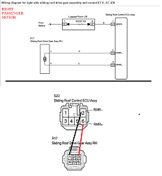
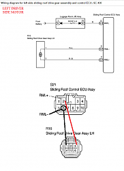
now before i start i want to confirm that autozone diy is only wrong at pin 5 for negative power to left motor. Its 2 and 6 for both motors at ECU end and 1 and 3 for both motors at motor end. so Tarheel your chart was right and ecu is same through out all years.
so here are the diagrams with the pin corrected for left side
1) ok so i first tested the resistance between one end of wire to other.
Right Side
ecu pin 2 to 1 (negative -) resistance - 000
ecu pin 6 to 3 (positive + ) resistance - 000
Left Side
ecu pin 2 to 3 (negative -) resistance = 000
ecu pin 6 to 1 (negative -) resistance = 000
2) Then i decided to test resistance directly at the motors and this is what i got
Right Side Pin 1 and 3 Resistance= 003
Left Side Pin 1 and 3 Resistance = 001
guys does this mean my right motor is bad? and just to remind when my roof sits in the trunk and pauses so I try switch, and i can see the roof try to pull down constantly , there is definitely uneven movement comparing both sides. Shall i go ahead and buy a new motor with gear assembly?
Thank you so much guys
so i did the tested from other end today.
now before i start i want to confirm that autozone diy is only wrong at pin 5 for negative power to left motor. Its 2 and 6 for both motors at ECU end and 1 and 3 for both motors at motor end. so Tarheel your chart was right and ecu is same through out all years.
so here are the diagrams with the pin corrected for left side


1) ok so i first tested the resistance between one end of wire to other.
Right Side
ecu pin 2 to 1 (negative -) resistance - 000
ecu pin 6 to 3 (positive + ) resistance - 000
Left Side
ecu pin 2 to 3 (negative -) resistance = 000
ecu pin 6 to 1 (negative -) resistance = 000
2) Then i decided to test resistance directly at the motors and this is what i got
Right Side Pin 1 and 3 Resistance= 003
Left Side Pin 1 and 3 Resistance = 001
guys does this mean my right motor is bad? and just to remind when my roof sits in the trunk and pauses so I try switch, and i can see the roof try to pull down constantly , there is definitely uneven movement comparing both sides. Shall i go ahead and buy a new motor with gear assembly?
Thank you so much guys