how can i make the flasher not flash?
 04-08-15, 10:01 PM
#1
Lexus Champion
Thread Starter

i'm really stumped here guys, since my lights are custom and have trailing LED turn signals, i need the turn signal flasher to stay always lit, anyone have any idea how i could do this? i'm really stumped and can't get it to work, i somehow managed to get the hazard button turn my blower motor on to full
here's a diagram of the flasher and how my flasher looks right now.
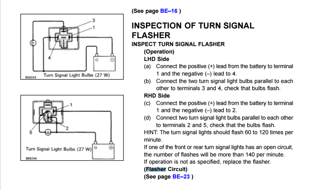
here's a diagram of the flasher and how my flasher looks right now.


 04-09-15, 07:23 AM
#2

I had a relay in my ranger go bad, when it did it just stayed open, (no flash) so that being said, what relays can you replace with the flasher relay that is just a simple constant voltage vs flash. like a headlight relay? im just tossing out Ideas, but wouldnt that just be an on? bypassing the actual flasher relay.
04-09-15, 10:16 AM
#3

need to see the diagram of the flasher circuit. EMS has a good idea, although I am not sure that relay controls the rate of flashing, rather it might just turn that circuit on or off for the left of right side.
I thought the rate of flashing though had to do with the flasher box module in the trunk that you normally change with the tail lights, since you have to swap that out to fix hyperblink or change the capacitor to change the rate of hyperflink. My thoughts that replacing the capacitor with jumper wires would give you close to a constant 12V as the capacitor in combination with the resistor is what they use on electrical circuits to control the rate of ouput from the capacitor.
basically the flashing rate is how fast the circuit can fill up the capacitor with voltage before it jumps across the capacitor and yeilds an output only for that short amount of time.
removing the capacitor completely should give you more of a constant output on that end unless they have a more advanced circuit in there (probably not).
in simple speak, find relay flasher box in trunk, open it, jump capacitor, see what happens. if not working then need to think harder and maybe change its accompanying resistor as they usually work in conjuction but bypassing the capacitor should do the trick theoretically.
here is the thread I was referring too.
https://www.clublexus.com/forums/sc-...aillights.html
here OLT (another electrical engie) is talking about a capacitor feeding the timing chip.
that is not great news because the simple jumping of the capacitor as I said above might not work as ist an input to this chip and not the actual output to the lights.
IF that is the case then the timing chip may not like the capacitor not being there entirely, and will either not work as intended and stay on of off all the time (on all the time would be good for you), or it could ruin the IC chip).
now I am thinking maybe just find the ouput line of the IC chip and wire 12v to it if nothing else works. you can cut the original trace even to disconnect the original output but there is likely a cleaner way like removing one leg of a resistor or cap down stream and tying in there.
basically would need some experimentation unless OLT actually did this at some point.
*edit* now that I thought of it for another minute, on the wire harness plug for the flasher unit there must be an output wire going to the actual turn lights, and an input wire from somewhere telling it to turn on.
might be the best/easiest place to bypass the whole flasher box and put the input wire to the output wire right there at the connector. if the input wire does not give the 12V and is a low level signal, then just a simple relay you can get at any shop would be needed to supply 12V to the output wire when the input wire is on = problem solved.
now you need to find a listing of the pins and wires coming off the flasher box.
Last edited by Ali SC3; 04-09-15 at 10:39 AM.
04-09-15, 03:19 PM
#4
Lexus Champion
Thread Starter
need to see the diagram of the flasher circuit. EMS has a good idea, although I am not sure that relay controls the rate of flashing, rather it might just turn that circuit on or off for the left of right side.
I thought the rate of flashing though had to do with the flasher box module in the trunk that you normally change with the tail lights, since you have to swap that out to fix hyperblink or change the capacitor to change the rate of hyperflink. My thoughts that replacing the capacitor with jumper wires would give you close to a constant 12V as the capacitor in combination with the resistor is what they use on electrical circuits to control the rate of ouput from the capacitor.
basically the flashing rate is how fast the circuit can fill up the capacitor with voltage before it jumps across the capacitor and yeilds an output only for that short amount of time.
removing the capacitor completely should give you more of a constant output on that end unless they have a more advanced circuit in there (probably not).
in simple speak, find relay flasher box in trunk, open it, jump capacitor, see what happens. if not working then need to think harder and maybe change its accompanying resistor as they usually work in conjuction but bypassing the capacitor should do the trick theoretically.
here is the thread I was referring too.
https://www.clublexus.com/forums/sc-...aillights.html
here OLT (another electrical engie) is talking about a capacitor feeding the timing chip.
that is not great news because the simple jumping of the capacitor as I said above might not work as ist an input to this chip and not the actual output to the lights.
IF that is the case then the timing chip may not like the capacitor not being there entirely, and will either not work as intended and stay on of off all the time (on all the time would be good for you), or it could ruin the IC chip).
now I am thinking maybe just find the ouput line of the IC chip and wire 12v to it if nothing else works. you can cut the original trace even to disconnect the original output but there is likely a cleaner way like removing one leg of a resistor or cap down stream and tying in there.
basically would need some experimentation unless OLT actually did this at some point.
*edit* now that I thought of it for another minute, on the wire harness plug for the flasher unit there must be an output wire going to the actual turn lights, and an input wire from somewhere telling it to turn on.
might be the best/easiest place to bypass the whole flasher box and put the input wire to the output wire right there at the connector. if the input wire does not give the 12V and is a low level signal, then just a simple relay you can get at any shop would be needed to supply 12V to the output wire when the input wire is on = problem solved.
now you need to find a listing of the pins and wires coming off the flasher box.
I thought the rate of flashing though had to do with the flasher box module in the trunk that you normally change with the tail lights, since you have to swap that out to fix hyperblink or change the capacitor to change the rate of hyperflink. My thoughts that replacing the capacitor with jumper wires would give you close to a constant 12V as the capacitor in combination with the resistor is what they use on electrical circuits to control the rate of ouput from the capacitor.
basically the flashing rate is how fast the circuit can fill up the capacitor with voltage before it jumps across the capacitor and yeilds an output only for that short amount of time.
removing the capacitor completely should give you more of a constant output on that end unless they have a more advanced circuit in there (probably not).
in simple speak, find relay flasher box in trunk, open it, jump capacitor, see what happens. if not working then need to think harder and maybe change its accompanying resistor as they usually work in conjuction but bypassing the capacitor should do the trick theoretically.
here is the thread I was referring too.
https://www.clublexus.com/forums/sc-...aillights.html
here OLT (another electrical engie) is talking about a capacitor feeding the timing chip.
that is not great news because the simple jumping of the capacitor as I said above might not work as ist an input to this chip and not the actual output to the lights.
IF that is the case then the timing chip may not like the capacitor not being there entirely, and will either not work as intended and stay on of off all the time (on all the time would be good for you), or it could ruin the IC chip).
now I am thinking maybe just find the ouput line of the IC chip and wire 12v to it if nothing else works. you can cut the original trace even to disconnect the original output but there is likely a cleaner way like removing one leg of a resistor or cap down stream and tying in there.
basically would need some experimentation unless OLT actually did this at some point.
*edit* now that I thought of it for another minute, on the wire harness plug for the flasher unit there must be an output wire going to the actual turn lights, and an input wire from somewhere telling it to turn on.
might be the best/easiest place to bypass the whole flasher box and put the input wire to the output wire right there at the connector. if the input wire does not give the 12V and is a low level signal, then just a simple relay you can get at any shop would be needed to supply 12V to the output wire when the input wire is on = problem solved.
now you need to find a listing of the pins and wires coming off the flasher box.
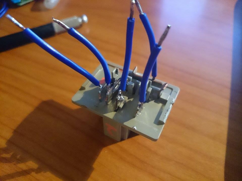
i don't get what box anyone ever talks about, my tail lights have nothing there and the relay controls the flashing of my lights for me. when i had regular LEDs they were hyperblinking obviously and replacing the metal shunt inside the flasher relay with a high wattage 10ohm resistor fixed the hyperblink. the relay definitely controls blinking because it's not just a regular relay on the inside, it has a capacitor, some coils, a few resistors and a whole bunch of other stuff inside it as well. take a look for yourself.
and i obviously took mine apart, gonna try to put it back together and somehow jumper whichever part is the intermitter or whatever you wanna call it.

where you see the messy solder, that's where i had the resistor
 04-09-15, 04:37 PM
#5
Driver School Candidate
iTrader: (1)

Join Date: Aug 2008
Location: CO
Posts: 48
Likes: 0
Received 0 Likes
on
0 Posts
Jumper 1 to 3 and 1 to 5 in the socket? If you don't want it to flash, that should do it. I don't see why you want that though.
What is lhd and rhd in the directions? Left and right hand drive?
What is lhd and rhd in the directions? Left and right hand drive?
04-09-15, 10:36 PM
#6
Lexus Champion
Thread Starter
you would think jumping 1 to 3 and 1 to 5 would work but it doesn't, can only have either one or the other, when you connect both nothing happens for some reason only the hazard works then. i don't want it to flash because this
https://www.clublexus.com/forums/sc-...il-lights.html
https://www.clublexus.com/forums/sc-...il-lights.html

Trending Topics
04-10-15, 09:47 AM
#8
Lexus Champion
Thread Starter
yea i've been soldering quite a bit. so i removed the capacitor that people were replacing to stop hyperflash and just jumped it and only the hazards work now. i'm gonna check if i blew any fuses but otherwise i'm completely lost on what to do lol. also realized that in direct sunlight, my turn signals are invisible lol, gonna have to address that somehow
04-10-15, 10:05 AM
#9
sorry I thought they were 2 seperate things but I guess that is the relay pictured. ok got it. so there is no connector with wires, just the pins coming out of the relay?
so removing the cap doesn't work cause the timing chip gets messed up as OLT hinted at, it can only affect the timing in a certain range and out of that range the timing chip gets confused which is the actual thing outputting the signal on a different pin.
Probably jumping whatever it is before the capacitor or whatever pin has the 12V into the timing chip, to the output pin of the timing chip might do something else like bypass the timing chip since you don't need any timing you just want 12v constant to go through when the circuit is complete instead of 12v pulses.
normally what they do is change the capacitance to tune the timing chip for hyperblink, but you dont want any timing function at all, so it might be doable actually once we know the right pins for that chip.
the timing chip is probably the black flat chip in the middle left hand side of your picture, its covered by the resister and the capacitor so I can;t read the number on it, but if you give me those numbers and letters, we can pull the manual for it, and it will tell us which one is the output pin or if there is another output pin that has the right signal. sometimes they use a generic timing chip that will have different outputs on it and they will generally just use one, let me know what the numbers are.
Last edited by Ali SC3; 04-10-15 at 10:18 AM.
04-10-15, 10:24 AM
#10
Lexus Champion
Thread Starter
Had a blown fuse. Jumping the capacitor worked. Thanks for the help guys. I'll post a video tonight cz in daylight they're very di. You think tinting them would make the turn signal more apparent cz of contrast?
04-10-15, 12:29 PM
#13
Lexus Champion
Thread Starter
do you guys think tinting the turn signal will make it more noticeable in sunlight? because i think what's happening is the sunlight is lighting up the inside of the light and making the LEDs seem dim.