2JZGE Na-T TT Ecu Mod
 07-31-12, 07:53 AM
#196

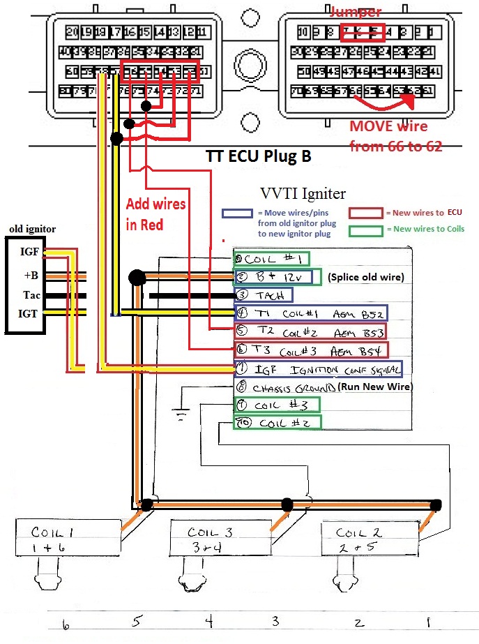
Yes, you have to do the wiring on the first page, then follow the coilpacks wiring. Just ignore where it says AEM ecu.

you should print them out and look at them side by side.
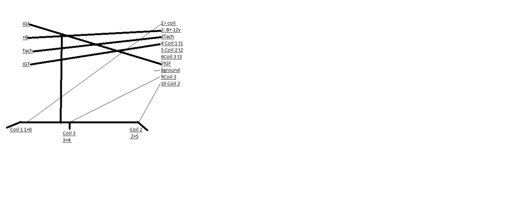
T1 T2 and T3 is the same as the IGT 6, IGT 5 and IGT 4 on the tt ecu diagram, look at the pin numbers.
On the AEM, IGT 1 and 6 are connected together internally, 2 and 5 are connected together internally, and 3 and 4 are connected together internally, so you only have to connect 3 wires and everything works great.
since you do not have an aem, you have to connect IGT 1 and 6 together, IGT 2 and 5 together, and IGT 3 and 4 together.
This is basically what my diagram on the first page is showing. you are connecting the pairs of IGT's together at the ecu when using vvti ignitor.
Due to the overwhelming amount of basic questions I am being asked repeatedly, I am not answering questions via pm anymore.
Post it in here and I will respond, that way im not answering the same questions over and over again.
you should print them out and look at them side by side.
T1 T2 and T3 is the same as the IGT 6, IGT 5 and IGT 4 on the tt ecu diagram, look at the pin numbers.
On the AEM, IGT 1 and 6 are connected together internally, 2 and 5 are connected together internally, and 3 and 4 are connected together internally, so you only have to connect 3 wires and everything works great.
since you do not have an aem, you have to connect IGT 1 and 6 together, IGT 2 and 5 together, and IGT 3 and 4 together.
This is basically what my diagram on the first page is showing. you are connecting the pairs of IGT's together at the ecu when using vvti ignitor.
Due to the overwhelming amount of basic questions I am being asked repeatedly, I am not answering questions via pm anymore.
Post it in here and I will respond, that way im not answering the same questions over and over again.
Last edited by Ali SC3; 07-31-12 at 08:03 AM.
 07-31-12, 10:20 AM
#197

Yes, you have to do the wiring on the first page, then follow the coilpacks wiring. Just ignore where it says AEM ecu.
you should print them out and look at them side by side.
T1 T2 and T3 is the same as the IGT 6, IGT 5 and IGT 4 on the tt ecu diagram, look at the pin numbers.
On the AEM, IGT 1 and 6 are connected together internally, 2 and 5 are connected together internally, and 3 and 4 are connected together internally, so you only have to connect 3 wires and everything works great.
since you do not have an aem, you have to connect IGT 1 and 6 together, IGT 2 and 5 together, and IGT 3 and 4 together.
This is basically what my diagram on the first page is showing. you are connecting the pairs of IGT's together at the ecu when using vvti ignitor.
Due to the overwhelming amount of basic questions I am being asked repeatedly, I am not answering questions via pm anymore.
Post it in here and I will respond, that way im not answering the same questions over and over again.
Your help is greatly appreciated!
 07-31-12, 10:56 AM
#198
no problem, I like to help out but I need to keep it all in one place where everyone can see the responses.
There is alot of interest in this mod lately and it is much more efficient if the missing info is addressed here so we can all be on the same page.
If anyone gets stuck on something post it up, thats what the thread is for.
I just don't have the time to walk everyone through it via pm so I am trying to make the walkthrough better,
and hopefully as more and more members start doing the mod, you can also help eachother out or even me with upgrading it.
It took me 4 months to get it right with just the pinout diagram and going off of captdales thread.
The missing piece of the puzzle is what you see on page 1 that lets us use the vvti ignitor/coils and keep the stock intake manifold.
the vvti coilpack wiring info with the AEM is old hat, was covered on SF a long time ago.
Last edited by Ali SC3; 07-31-12 at 11:01 AM.
07-31-12, 01:33 PM
#199
k everything is done.... me and my guy are just confused about where the t1 and t2 go since we dont have an aem?
i think maybe were just confusing ourselves due to looking at two diagrams....
All the coilpack wiring is finished at the igniter, and im left over with T2 and T3 at the igniter , which in your digram are going to aem. where do they go in my application??
Also to be super clear, in addition to this wiring at the igniter in the diagram, At the ecu the 52 to 57 53 to 56 and 54 to 55 still need to be jumped correct???
when this is all done im gonna make some diagrams excluding the AEM stuff, for the simples like me who are confused as **** LOL
UPDATE: something quicksc4 said in another thread made it click for me, im guessing i need to run the remaining 2 straight to pins 55 and 56 at the ecu.
Last edited by sj408; 07-31-12 at 04:25 PM.
07-31-12, 06:54 PM
#200
Yes you have to the add/run the wires for t2 and t3.
So you will end up with 3 IGT wires going from the ecu to ignitor (1 stock and 2 you just added).
The remaining 3 IGT pins are jumped to the 3 IGT wires above.
I will try and update the diagram to be more clear when i get some time.
So you will end up with 3 IGT wires going from the ecu to ignitor (1 stock and 2 you just added).
The remaining 3 IGT pins are jumped to the 3 IGT wires above.
I will try and update the diagram to be more clear when i get some time.
Last edited by Ali SC3; 07-31-12 at 06:57 PM.
The following users liked this post:
LEXXIUM (12-24-16)
07-31-12, 10:34 PM
#204
Also Ali, how did you mount your coils??? i was thinking maybe just a short screw or is that a no no?
08-01-12, 09:30 AM
#205
Driver

Join Date: Mar 2012
Location: GA
Posts: 104
Likes: 0
Received 0 Likes
on
0 Posts
Man i still have to find 440's and order coils (probably get them frm QuickSc4) so im just driving with this suckish safc on 5psi prolly just leave it this way till i get all the parts which hopefully will be this weekend might have to break down and get the 7m injectors which i really dont want to do where did you find your injectors?
08-01-12, 09:34 AM
#206
Driver
Join Date: Mar 2012
Location: GA
Posts: 104
Likes: 0
Received 0 Likes
on
0 Posts
Hey Ali what all types of Top Feed Hi Imp Injectors will work i see a few different types but not sure about fitment no so much concerned about pigtails that can be taken care of
08-01-12, 09:48 AM
#207
gte & na-t
iTrader: (44)
Join Date: Jan 2007
Location: Maryland /Germantown
Posts: 5,139
Likes: 0
Received 7 Likes
on
7 Posts
If you map sensor is not defective , then you must wired it wrong , it's one of them. there is a reason why you have the code 31 .
remove the map sensor wiring and redo it , loose wire and crappy connection.
the coils can't be mounted because you don't have the holes in the head from the factory, that cylinder head never had a COP setup .
Just drop them in the boot on the bottom of the coil with keep the coil on the plug and it will not move.
i don't know any side feed 440 with top feed, mk3 is low imp it will require a resistor box, just get one from a V6 honda accord/ 91+ acure legend and wire it in.$7 it won't break the bank i am sure and the injector connectors should be the same as your stock ones.
gl
08-01-12, 10:02 AM
#208
Driver
Join Date: Mar 2012
Location: GA
Posts: 104
Likes: 0
Received 0 Likes
on
0 Posts
Yea gonna probably just go that route i just didnt want to do all the wiring is it any special order they have to be wired or do they just need the 12v running thru the resistor
08-01-12, 10:09 AM
#209
I just dropped my coils in, they can hardly move around with all the wiring also.
Someone on club na-t fashioned a little metal bracket for each one, check out my sticky for the distributor delete over there.
Rc engineering was known for making 440's top feed high impedance. they look like the oldschool bosch kind.
you are going to be re-wiring either the clips or the resistor pack in most cases, like the rc ones i got I had to rewire the clips.
If you get 7m ones you will be doing the resistor pack but the clips are plug and play.
so i wouldnt be concerned that much with the adapters, just make sure you get the clips with the injectors if they are not the 7mgte kind.
If you use a mk3 resistor pack, there are only 3 leads so you pair 1 and 6 together, 2 and 5 together, and 3 and 4 together (sound familiar?).
If you use a mk4 resistor pack, there are 6 leads you wire each injector to its own lead.
Did you guys touch the wiring for the distributor at all other than the grounds at the ecu.
I still am trying to understand why both of you are getting a map code, for me i had 2 of the wired swapped. on the map sensor.
For code 52 does that happen when you hit the wall. knock code should go away if you reset the ecu. if it comes right away could be a bad wire.
BTW I wouldn't keep trying to rev it past where it doesn't want to go with the map code lit up. your timing will be all over the place.
you need to get it sorted out and then it will work 100%.
I am gonna go check my map sensor and IAT wiring again tonight to verify.
do you guys have different colors at your maf plug? if so list them here and I will tell you what each on is.
Last edited by Ali SC3; 08-01-12 at 10:17 AM.
08-01-12, 10:32 AM
#210
gte & na-t
iTrader: (44)
Join Date: Jan 2007
Location: Maryland /Germantown
Posts: 5,139
Likes: 0
Received 7 Likes
on
7 Posts
i wouldn't use an mk3 resistor box because they fire in batch.
maf wires have different colors depending on the year 92-95 should be the same. remember don't go by color go by pin location.
maf wires have different colors depending on the year 92-95 should be the same. remember don't go by color go by pin location.

