When you click on links to various merchants on this site and make a purchase, this can result in this site earning a commission. Affiliate programs and affiliations include, but are not limited to, the eBay Partner Network.
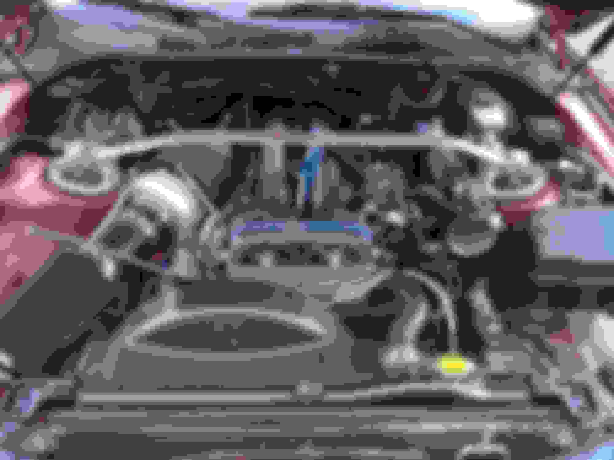
Heres what I'm working with, the pale green wire is still in question. The black and white wire is supposed to be the tach because its found over at the coil as well.
Car cranks but just doesn't fire, and the fuel pump seems to be stuck on like its priming but never finishes priming.
Maybe I missed it in an earlier post, but are you using the stock ge coil? From that top pic you don't have the other coils wired up if you are using the vvti coils.
You can also remove the vsv for that vacuum canister, one of the lines came from the vsv into the canister.
I made some brackets out of some aluminum stock I had, made a template out of thin cardboard first:
Then cut them out, shaped them better and drilled the holes. Here is how they turned out (I'll probably powder coat them black later, I don't feel like getting my pc crap out just for those).
Those brackets looks great, mine are still floating around like bobble heads but they get the job done. I try and use the long plug wires to wedge them in once all the wires are in its not so bad.
Originally Posted by 187
To update I tried starting my car today to no avail, I will be double checking the wiring this week.
I confirmed my IGT is white/green wire at the ecu, but my "tach" wire which is a pale green connects to pin 20 NOT 16.
I also found the pale green wire on the cruise control plug which leads me to believe it is the tach but just not in the right spot?
where are you talking about pin 20 or 16, the tach wire is already there at the old ignitor, just plug it into the new ignitor. that is all you need to do for the tach wire do not run any new wires to the ecu.
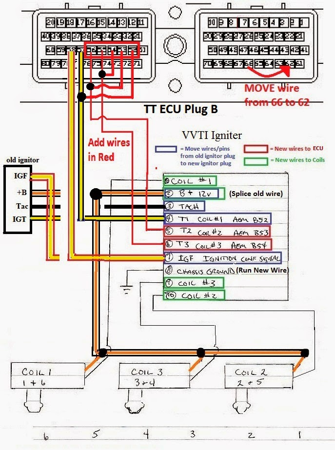
I updated the pin positions for the ignitor on page 1 with wire colors from a supra.
if you need help with those still list out the wire colors and what you think they are and I can go over them somehow.
Originally Posted by eblick99
i have a question about FFIM and IACV and how that could affect timing. Since I have no IACV i have the TB cracked open to compensate, meaning the ecu is going to read throttle is open when i do the jumper for timing. Should I then have my TPS set at 650 with TB fully closed or should i set it at 650 when i have it cracked to get proper idle?
that said is there a way to adjust timing without starting the car, and just manually set timing from 10 down to 6~7 and bypass the jumper business?
the timing must be set with the tps in the mostly closed position, or it wont let you do it, engine sound will not change when you insert jumper. If you crack the throttle body open some to let more idle air in, then you need to turn the tps back that same amount. there will only be a little bit you can crack it open and still let the tps close fully, but there is a little adjustment on it.
if you put the jumper in and the sound doesn't change, then you have gone too far.
also note you may just want to live with the 650rpm and the 800 with the a/c on, as I have found that even after cracking the throttle body a bit the ecu willl re-learn its 650rpm. you have to crack it quite a bit for it to not to be able to idle down, and see if you are still in the right tps range then. with the q45 it may be possible since its so large it will let in more air when cracked.
Originally Posted by eblick99
p.s. here is a pic of where im at; TB and FFIM installed, im about to go back out and turn the key to the "on" posistion and see what works/what doesnt; prime new fuel injectors and see if theres a leak...or worst case if something decides to smoke...
Q45 TB is such an odd diameter tried all different sizes of coupler, went with one thats pretty snug, better than loose. stupid t bolt clamps wont fit it either, had to use an ugly clamp. still need to fix all the vacc hoses and IC pipes and get the IAT installed somewhere, so it will be a while before i can start it. that throttle cable is so close yet so far. im going to have to make a short extension.
for the q45 I order a 3.5" coupler and clamp, works like a charm. good luck let us know how it goes. if the stock throttle cable is just like an inch short you can try a 4 cylinder camry cable it will have the best chance of working before going to the extremely very long landcruiser cable.
Originally Posted by Coldworld
Who all has done this swap and has it worked well
Many people, actually everyone who has done it on obd1.
96+obd2 we have like a 50% success rate going. about to be 66% or 33% soon.
Originally Posted by 187
Heres what I'm working with, the pale green wire is still in question. The black and white wire is supposed to be the tach because its found over at the coil as well.
Car cranks but just doesn't fire, and the fuel pump seems to be stuck on like its priming but never finishes priming.
I am pretty sure you have most of those wire colors wrong. the power wire black/red is in the wrong spot. also the ecu plug you should be looking at the big 80 pin one that is 2 plugs connected together with the screw in the middle, not the 40 pin one that is by itself. I don't think you are looking at the right wires. there isn't even a green wire on the ignitor plug. check on the right ecu plug and the stock coil wire will be next to the red/yellow wire where I showed it in the diagram above. it will also be the same color as the 2nd wire at the stock coil.
all the wires you need when re-using the stock coil are already there at the ignitor. you just had to repin them. also the new ignitor needs a ground wire which I can see is not installed.
can you do me a favor and take a picture of the 2 wires that go to your stock coil. one will be black/(red or orange), the other wires is ???? let me know the color
a picture would be great.
I wish you had taken a picture of the original ignitor plug before removing the wires now they are all jumbled up.
Originally Posted by killersqrl
Maybe I missed it in an earlier post, but are you using the stock ge coil? From that top pic you don't have the other coils wired up if you are using the vvti coils.
If you are using the stock distributor and coil still, then you just use the vvti ignitor without the vvti coils. its like the slim version of the mod that keeps the whole distributor.
First wire in the pic is blue/white which is the negative side of the coil
The black and white wire with the green grommit connects to the + side coil.
The red black is actually ground to chassis that i added , it was not there stock.
The red and yellow is normal and in the normal spot
Yellow green goes in with the 5 pin jumper for stock coil
This just leaves the pale green wire that matches up to the pin 20 on plug A
Sorry I'm working from my phone, to be specific at the coil the two wire plug has black/white and blue/white.
alright that helps, lets see if we can get it sorted out
so you added the red/black as a ground wire, so then that is in the right spot (normally blck/red is 12v so you threw me off)
The red/yellow should 99% be the IGF so its in the right spot as well.
now the 4 wires on the left is where the problem is then.
from what I can see if you say the black white is the + side of the coil, then it should be in pin 2 not pin 3.
Pin 2 is +B (battery) 12V which is the same wire that goes to the coil and ignitor, so maybe its as simple as swapping pin 2 and 3.
you say the blue/white and the black/white show up at the stock coil?
that means one of them is power wire +12V and one of them is the signal wire for the coil.
so the signal wire for the coil should be in pin 1, and the power wire +12v should be in pin 2.
right now you have one of them in pin 1 and one of them in pin 3.
easiest way to figure out which is power and which is signal, is to pull the connector off, put the key in the on position (don't crank it), and see which one is showing 12v with a meter, touch one end to that pin and the other to chassis ground you should get 11-12V.
the other one will be the signal wire.
also note the power wire is usually a bit thicker than the other wire, but not always.
then pins 3 and 4 are the only ones left.
one will be tach #3, and the #4 will be the wire from the ecu to the ignitor for coil 1 (IGT).
Pin b57 at the ecu if you look at this pin you will know the color for pin 4 IGT.
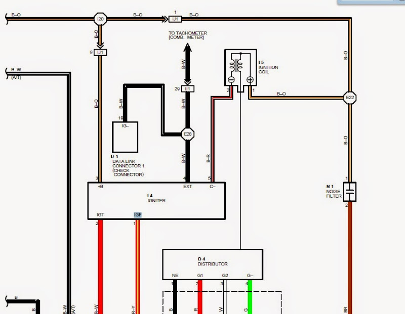
the last one left will be your tach wire. it does not go to the ecu believe it or not, on our cars it goes from the ignitor to a body plug, and then on to the cluster. so this will be the last one by elimination.
dont forget to look at these.
Originally Posted by Kris9884
Man, the more I read this the more I regret selling the 300..
There are plenty more out there just get another one. I used to worry about engine management the most when taking on these projects now I know if I pick up a 92-95 sc300 I can have a turbo ecu on it supporting 4-500hp in about a half a day. Also the more you do it the faster you get
before I would have to factor in an aem ems and a tune before I can enjoy it. now I can just install it all and start and drive it I don't know why people weren't doing this a long time ago.
I actually had it the other way before, i know the power isn't in the right spot in the picture. The tach was the only wire i couldn't trace and it was driving me crazy. I'll test the wire but it is thicker for sure. The green one must be the tach and i have to check my ecu pins I'll update later
I've noticed lately that upon a later hot start the car will idle lean for a few minutes , and RPM will be lower at idle. After driving it fixes itself and idle A/F is back to 14.7-15.1:1.
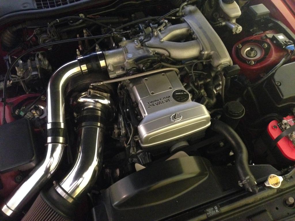
My theory is that the IAT sensor is being heat soaked after driving and then shutting the car down. When I go to start it back up the sensor is heat soaked and it takes a few minutes to cool down. I've got the IAT bung welded onto the bottom of the upper IC pipe near the K&N filter in the front passenger side of the engine bay. Should I move the sensor to the piping out of the engine bay? I figured this was far enough away from the turbo to keep it from heat soaking but maybe not.
Does the GTE ECU compensate the idle A/F based on the IAT temperature? Would a hot temp cause a lean condition like I'm experiencing?
Could my Apexi SAFC set at -21% across the RPM band to compensate for 550cc injectors be causing the weird adjustments?
I've read that back in the day, BPU tunes would remove the IAT and just run a resistor that would tell the ecu a constant voltage, or constant IAT temp, which would reduce the idle A/F swing adjustment.
IAT Sensor is in the piping farthest left, bottom of the picture, on the underside.
you are close and right in your observations. its called the hot start condition.
You have it setup right, no need to change it, this is normal on these motors, its not the ecu or the sensors.
In fact if it wasn't happening then that would be something to be concerned about. its happens on both JDM and USDM ecu's because its actually a motor issue.
what happens is that the engine block/coolant temperature actually rises for the first 10 minutes after you shut your car down because there is no coolant circulating. when you go to start it the engine is so hot it actually needs a richer mixture than normal to get the same AFR. the ecu can still ready the sensors and should know the right amount to inject based on the VE curve, but what happens is the motor is so hot it essentially changes the curve and the ecu is not designed to compensate so it idles lean until the block and combustion temperatures stabilize again which stabilizes the AFR.
now the funny thing is they tried to solve this on n/a obd1 california models, and all obd2 models.
the blue vsv by the fuel pressure regulator is the fix and what it does is it cuts off vacuum to the fuel pressure regulator on a hot start. so instead of seeing -8 psi of vacuum, it sees 0 psi ambient air, and since the fuel pressure regulator rises with pressure, thats like 8 psi more fuel pressure than it should be seeing which richens up the mixture and cures the problem, as the o2 sensor can sill pull fuel to get it close under those conditions.
the thing is that this is purely for emissions. idling lean after a hot start is normal, well because the engine is really that hot it is burning all the fuel. you won't detonate or throw pistons out the block, its pretty much only at idle after a hot start. what this does do is hurt emissions, as after a hot start a lean mixture will not get the catylitic converter working right and alot of emissions happens as a result. that is why cali went the extra mile and put that and 4 wire heated o2 sensors on all cali 92-95 models.
another problem with those and na-t, is if you leave it in and boost after a hot start, the fuel pressure regulator does not see positive boost, so you are actually cutting out fuel now, and is down right dangerous and could destroy the motor on the first big pull. I would rip that blue vsv out or at the very least route the vac line around it ant not through it, just take the 2 vac lines off of it and connect them together = problem solved.
its not due to yout safc, so don't worry. you can idle as lean as -16 for quite an while on these motors, they are strong as bull =)
also the larger injectors you go, I have heard the leaner it goes on the hot start. the solution though is just to ignore it and start driving, the driving map is so rich before the o2 kicks in you should see the right afr's as soon as you are off idle.
also when they used to resistor the IAT temp sensor, some type of VPC would be installed at the same time usually on usdm maf models.
If you have the IAT in the coolant piping you are good, the ecu does not use it a whole lot I think it only adds fuel when its cold, and is 0 trim when its warm-hot, and it expects it to heatsoak actually so it can go to a 0 trim condition, cause the stock one heatsoaks.
I know every GTE owner with larger injectors even usdm complains about this same thing, its one of the only things that isn't 100% solid on the stock ecu.
also it does the same thing on an aem ems, ask me how I know =)
Toyota does most of their fuel enrichment when cold and heating up and once it reaches normal temp the trims usually come down to 0.
So car is stil in the same state, I pulled three codes from the ecu.
P1652
P1662
P1400
It seems as though it would be a connection problem or something.
Fuel pump is constantly priming with no start and it stays priming after the no start.
so you have an IACV code, an egr code, and a trac tps code.
the car wont run properly with a P1400 trac tps code, but it should start still.
I would fix this code though later with the resistor trick its on supraforums somewhere, read this. http://www.supraforums.com/forum/arc.../t-351835.html
did you do the wire elimination above and check your wires on pins 1-4 of the ignitor?
that will have to be right.
you are using an obd2 ecu right? make sure you did the 550cc injectors and the TT supra maf. it likely will not start with the stock injectors if that is what you are trying, what all have you done again? you have a list?
tt maf should be straight swap no rewiring usually
the map sensor should take power and ground from tps, but run new wire for signal wire.
and of course the jumpers for the ignition at the ecu. that should be about it more or less, missing any of those?
Yes I have the Igniter set up as it should be, 550cc injectors, map maf and ecu from an obd2 supra all in. Jumper and signal wire are hooked up at the ecu. So I don't think anything is missing.
I'm a little confused by the link, I did take my cruise control out but as far as i know I don't have traction control?
That sounds like you have all the right parts on there. Your car may not have traction control but all USDM 2jzgte's have traction control, so the ecu you are using is looking for it. good news is it can be bypassed with the resistor trick.
It is a bit odd there is an IACV code, unless you didn't plug the IACV in. you may have to step on the throttle like 5-10% to get it to start without an IACV, so try modulating the throttle next time you are cranking it but don't push it more than half way down usually.
Originally Posted by ashtray
Can't wait until I see this at 100% for OBDII W58 peeps. Thankfully I'm still gathering parts and info in this daily visited thread.
hopefully it will get more consistent for obd2. I think it you take your time and double check every wire you move you should be alright. obd2 is quirky though I haven't heard much any troubles on obd1 at all except for the whole auto trans lock up thing but thats with both ecu's.
anyone with a big turbo should go manual or tt/built auto anyways though really.

 09-23-14, 03:54 PM