2JZGE Na-T TT Ecu Mod
 03-29-14, 10:12 AM
#1516

nothing looks out of place, but the connector for the egr probe is between the back of the upper intake manifold and the firewall. you have to look down from the back area of the motor by the brake booster, its hard to see unless you know its there, there is a large grey connector that should be plugged in, sometimes its unplugged when uninstalling and missed when re-installing. give it a check, its not shown in the pics.
if its a old fault code it may go away, you can even try resetting the ecu or using the scanner and clearing the codes every time you get rid of a new fault code to give it a chance to relearn with the new parameters better. It may just go away by itself when you do that.
if its a old fault code it may go away, you can even try resetting the ecu or using the scanner and clearing the codes every time you get rid of a new fault code to give it a chance to relearn with the new parameters better. It may just go away by itself when you do that.
 03-29-14, 07:14 PM
#1517
Pole Position
Join Date: May 2012
Location: Arizona
Posts: 301
Likes: 0
Received 0 Likes
on
0 Posts
I put a jumper in between b41 and b42 and there was no difference. I also checked the plug behind the manifold on the drivers side. The one you can't really see but have to feel for it. It seems like it is plugged in.
Codes still present:
Sub - throttle position sensor
EGR circuit
Idle air control valve circuit
Automatic transmission circuit.
I am not seeing one for the traction control but still getting sub throttle code. *edit* never mind It popped up when I scanned it a second time.
Also, I let it idle for a little bit, and after about 30 seconds the rpms would rise and fall over and over again until it will almost die. This happens even if I slowly give it some gas, the rpms will go up and down.
I am looking at some wiring diagrams for the 1997 tt and the 1997 sc300 and on the supra diagram, one of the wires going from the sub throttle sensor connects to the throttle position sensor, but it does not go into either b41 or b42. There is a different wire from the sub throttle sensor that goes straight to the ecu.
Here is the wiring diagram for the 1997 lexus sc300 and how the sub tps and tps are wired. Also, I don't know if it is relevant, but my wire to b42 in my harness was already blue/red and not yellow and red. I don't know if they already converge earlier in the harness or not, and maybe that's why my wire is blue/red and not yellow/red.
Here is the 1997 supra ecu diagram
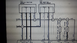
And here is the 1997 sc300 ecu diagram. Both are for the sub tps and tps sensors.
Last edited by BuffNStuff; 03-29-14 at 07:26 PM.
03-29-14, 10:44 PM
#1518
Pole Position
Join Date: May 2012
Location: Arizona
Posts: 301
Likes: 0
Received 0 Likes
on
0 Posts
Also, where is the Sub-TPS on the GE? If I dont have a plug for one, why was there already a wire going into the ECU for it? I am confused.
Last edited by BuffNStuff; 03-29-14 at 11:59 PM.
03-31-14, 11:06 AM
#1520
I think that diagram is saying if you don't have trac you have the blue/red wire which is a 5v wire already jumper ed there. I think if you have trac then it goes to the second tps and its VTA2 yellow/red, but yours wont have that.
I wonder why it would still give the code then, maybe its more advanced than odb1 detection or maybe we have to do something with the IDL pin. Ill have to do some looking into this one then that is how you get rid of it on odb1, or maybe it wants to see ground instead of 5v on that pin but I am not sure you want to just go out and test that because its possible to short something.
I know in the 97 manual there should be a troublshooting section for each fault code and it tells you the various things that can trip each code, that is usually where I head to on these ones sometimes it will be something simple listed right there that will set it off, and if sub tps goes off the trac one will go to.
03-31-14, 11:12 AM
#1521
found the info on it, it needs a resistor in that wire thats jumped from 41 to 42 looks like, and possibly another wire from 41 to the IDL2 circuit B63 with another resistor in it.
http://www.supraforums.com/forum/arc.../t-456179.html
so its a little more complex on the odb2, but 2 resistors should be easy for you guys by now with all the wiring you have been doing. in fact, I would just try the 10k resistor first and see if the light goes away, the 1mega ohm resistor may not be even necessary but if not then do both it should work as lots of people on SF have done it.
http://www.supraforums.com/forum/arc.../t-456179.html
if ur lookin at the pic above yall see there are 4 wires goin to the sub-tps...
E2 is the ground and you dont need to worry about it
we will call
VC = #1
VTA = #2
IDL = #3
now yall need two resistors....a 10k ohm 1/2 watt and a 1m ohm 1/2 watt.
now take the 10k ohm resistor and put it into #1 and #3....
next put the 1m ohm 1/2 watt into #1 and #2....
basically sj told me that when u test the sub-tps when it is opened, you should see 2-10.8k ohm between #1 and #3...(the 10k ohm resistor creates this). Then when u test between #1 and #2 you should see over 1m ohm (1m ohm resistor here). in essence the ecu thinks the sensor is there...and is open....
ill try to post pics....but its basiclaly like every other resistor mod on the supra....ur foolin the ecu by giving it what it wants.....some range of ohms that the sensor SHOULD be sending it.
Last edited by Ali SC3; 03-31-14 at 11:17 AM.
03-31-14, 11:24 AM
#1522
also figured out the 1662 is not for the EGR. its for one of the turbo vsv's, its for the exhaust bypass valve.
http://www.mkiv.com/techarticles/eng...bd2_codes.html
this is for the twins basically it just want to see a vsv connected there. should be an easy fix just wire in a spare vsv somewhere or maybe there is a resistor to make it think there is one but not sure, either way easy fix.
http://www.97supraturbo.com/Trouble%...1662%20EBV.pdf
http://www.supraforums.com/forum/sho.......-Any-ideas
The intake air control vale is similarly another vsv on the intake side of the twins system, not to be consued with the Idle air control valve (It is confusing got me a few times also). this is the same as above either takes a resistor or the actual vsv.
http://www.97supraturbo.com/Trouble%...652%20IACV.pdf
The RPM's fluctuating is usually a sign of the main tps being in the wrong position, try fiddling with it some.
The last auto trans code, well we will have to figure that one out if its not on supraforums already.. lol.
shouldn't be all that hard probably another resistor or the actual solenoid itself.
I think you may need one of those packs of resistors, probably like 10kohm ones with highest wattage they have at the store.
looks like one side of the vsv gets black/red which is switched 12v you can find anywhere by the ecu or in the engine bay (probably on your other vsv's also), and the other side goes to the pin on the ecu for that vsv.
so you would do 12V B/R > vsv or resistor > pin on ecu. do that for all the vsv;s you get a code for, and you can just use vsv's and not attach vacuum to them at all there is no feedback that will definately work leave 2 vsv's down by the ecu worst case the resistor doesnt work. you can even use ones with broken vac nipples I know I have one of those laying around at least.
IT does seem like odb1 does not care much for missing vsv's. odb2 is harder but should be well worth it in the end to have it all working and completely emissions friendly since none of those things are related to emissions at all. looks like your EGR is in fact working 100% fine since there is no code for it, its a different code number altogether usually a p0401 or p0402.
Last edited by Ali SC3; 03-31-14 at 11:56 AM.
03-31-14, 01:52 PM
#1524
haha yeah I was writing for a while there, I think I listed out above how to solve all the issues except for the trans, that will require some head scratching but as far as I know no one fails anything for trans codes, but that is not an excuse we will get it working the way its supossed to.
tps will need the resistors and the other 2 codes are just for vsv's which can be added or just find the right value resistor.
did a search and found that one also, its a 1kohm resistor between power and the pin at the ecu for the particular vsv. You're welcome =)
Look at post #4 shows it perfect.

from here:
http://www.supraforums.com/forum/sho...des-Resistor-s
tps will need the resistors and the other 2 codes are just for vsv's which can be added or just find the right value resistor.
did a search and found that one also, its a 1kohm resistor between power and the pin at the ecu for the particular vsv. You're welcome =)
Look at post #4 shows it perfect.
from here:
http://www.supraforums.com/forum/sho...des-Resistor-s
03-31-14, 02:38 PM
#1525
Pole Position
Join Date: May 2012
Location: Arizona
Posts: 301
Likes: 0
Received 0 Likes
on
0 Posts
If this works I will give you the biggest virtual hug ever. Hell, I'll PayPal you some beer money. I just got back from radio shack with the 2 resistors for the sub-tps. I'll try that out first.
03-31-14, 02:55 PM
#1526
lol no worries, just help out the next odb2 guy or pass it on. I already knew these things worked but just haven't done them yet. luckily these guys shared the info because its common for gte owners to go single and bypass the vsv's and delete trac but I am sure I could have also found the info on an older mr2 board or something, they basically work the same way as the turbo motors and generally most other toyotas post '86.
I have found if you do a google search for "supra" plus the odb2 code number, you will hit most of the relevant threads, like "supra P1400" then click on related threads under one of the major forums like CL or SF.
If you want to find a particular thing in this beastly 102 page thread, I also do a google search for tt ecu mod + the thing I am looking for and click under related threads and it shows the results from the different pages all on one page, makes searching through much easier.
03-31-14, 03:00 PM
#1527
Pole Position
Join Date: May 2012
Location: Arizona
Posts: 301
Likes: 0
Received 0 Likes
on
0 Posts
If I already have 5v to the sub tps pin without the jumper, doesnt that mean I can take out the jumper I made and just put the resistor inline on the wire that was already there?
03-31-14, 04:10 PM
#1528
Pole Position
Join Date: May 2012
Location: Arizona
Posts: 301
Likes: 0
Received 0 Likes
on
0 Posts
Okay so I took out the jumper wire I previously put in and then wired the resistor into b42 directly. After scanning twice, the p1400 code did not show up. However the traction control code did still show up. I am assuming this is what the other resistor is for?
Also just for reference. B42 already had the 5v. After I disconnected my jumper wire I put my multimeter to it and it showed 5v.
Also just for reference. B42 already had the 5v. After I disconnected my jumper wire I put my multimeter to it and it showed 5v.
Last edited by BuffNStuff; 03-31-14 at 04:15 PM.
03-31-14, 04:31 PM
#1529
Okay so I took out the jumper wire I previously put in and then wired the resistor into b42 directly. After scanning twice, the p1400 code did not show up. However the traction control code did still show up. I am assuming this is what the other resistor is for?
Also just for reference. B42 already had the 5v. After I disconnected my jumper wire I put my multimeter to it and it showed 5v.
Also just for reference. B42 already had the 5v. After I disconnected my jumper wire I put my multimeter to it and it showed 5v.
I will look more into the trac control code but let me know if doing the resistor to the IDL2 fixes it or not. I am assuming you cleared the codes and the memory with the scanner and trac code still came back after clearing? if not clear the codes and see what happens.
If there is no 5v wire on the IDL2 pin then use that jumper wire for that pin with the resistor inline.
03-31-14, 04:37 PM
#1530
now I know why jumping 5v does not work for odb2, it is smarter and the voltage trips are set to detect if its always fully open. so the resistor makes it somewhere in between the ranges it doesn't like. see P1400

It says the ecu would be in failsafe mode. in fact we have to fix the trac code P1630 its also on that list or it will also be in failsafe for some reason but I sort of doubt it would affect the fuel or timing.

good news is it looks like it doesn't light up the check engine light for the trac code, bad news is that I think its looking for the throttle control or trac ecu. may be another resistor type thing have to find the diagram for the throttle control ecu now.. gonna do some more looking around.

found these from here:
http://www.97supraturbo.com/1997%20S...ics-Engine.pdf
looks like there are 2 signals going from ecu to trac and vice versa. I am hoping resistors would work here also, and would not have to go through the trouble of installing a dummy trac ecu.
It says the ecu would be in failsafe mode. in fact we have to fix the trac code P1630 its also on that list or it will also be in failsafe for some reason but I sort of doubt it would affect the fuel or timing.
good news is it looks like it doesn't light up the check engine light for the trac code, bad news is that I think its looking for the throttle control or trac ecu. may be another resistor type thing have to find the diagram for the throttle control ecu now.. gonna do some more looking around.
found these from here:
http://www.97supraturbo.com/1997%20S...ics-Engine.pdf
looks like there are 2 signals going from ecu to trac and vice versa. I am hoping resistors would work here also, and would not have to go through the trouble of installing a dummy trac ecu.
Last edited by Ali SC3; 03-31-14 at 04:51 PM.