DIY for SC Cluster & Needles
 12-02-13, 11:45 AM
#16
How the needle gets calculated is by the base's weight vs. the arm's weight, and the entire needle. I lost my document when I did it awhile back, so I forgot the specs. If you notice the copper weight at the base, it's used to balance the needle to read correctly. As long as you don't gain too much weight over the original weight, then you'll be fine. I'd say 4-5 grains is max allowance. You'll need a fine electronic scale that reads in grains. Let's say if you keep the base's weight the same, and the needle reads high, then put some more weight on the arm. I used to epoxy a small piece of galvanize steel at the arm to keep it balance. Galvanize steel is light. One inch would weight about 2 grains. Again, I lost my doc.
 If your needle is too heavy and even if it reads correctly, it'll potential damage the tiny spring on the motor.
 12-02-13, 11:49 AM
#17
Driver
Thread Starter
Join Date: Sep 2013
Location: NY
Posts: 185
Likes: 0
Received 0 Likes
on
0 Posts
Fry's electronics has super fine insulated wire. It's like feather and won't affect the weight. I used it to fix my cluster.
How the needle gets calculated is by the base's weight vs. the arm's weight, and the entire needle. I lost my document when I did it awhile back, so I forgot the specs. If you notice the copper weight at the base, it's used to balance the needle to read correctly. As long as you don't gain too much weight over the original weight, then you'll be fine. I'd say 4-5 grains is max allowance. You'll need a fine electronic scale that reads in grains. Let's say if you keep the base's weight the same, and the needle reads high, then put some more weight on the arm. I used to epoxy a small piece of galvanize steel at the arm to keep it balance. If your needle is too heavy and even if it reads correctly, it'll potential damage the tiny spring on the motor.
How the needle gets calculated is by the base's weight vs. the arm's weight, and the entire needle. I lost my document when I did it awhile back, so I forgot the specs. If you notice the copper weight at the base, it's used to balance the needle to read correctly. As long as you don't gain too much weight over the original weight, then you'll be fine. I'd say 4-5 grains is max allowance. You'll need a fine electronic scale that reads in grains. Let's say if you keep the base's weight the same, and the needle reads high, then put some more weight on the arm. I used to epoxy a small piece of galvanize steel at the arm to keep it balance. If your needle is too heavy and even if it reads correctly, it'll potential damage the tiny spring on the motor.
I will be redoing them in the near future, this was a first so it will improve on the next go around. i looked into some wire guages and saw that 18 guage was recommended but i noticed it goes to 32 guage, might try to find that especially since the lenght is only 3 inches or so maybe 4.
Thanks Stevechumo
12-02-13, 12:40 PM
#18
Driver School Candidate

Join Date: May 2010
Location: Fl
Posts: 43
Likes: 0
Received 0 Likes
on
0 Posts
A DIY write-up would be great. I have no clue what to do with those needles, which is why I sent it away in the first place, but if there was something to walk me through how to do it, I might actually give it a shot. Thanks!
12-02-13, 01:45 PM
#19
Driver
Thread Starter
Join Date: Sep 2013
Location: NY
Posts: 185
Likes: 0
Received 0 Likes
on
0 Posts
I will also be pulling out my Climate and I have an additional radio i will working on to see about doing those light. I will be doing a DIY on all of it just give me some time to actually get it all together
12-02-13, 01:46 PM
#20
I see so using a counterweight might work but could mess the needle up. so better to lose weight and hope it works then adding alot of counterweight.
I will be redoing them in the near future, this was a first so it will improve on the next go around. i looked into some wire guages and saw that 18 guage was recommended but i noticed it goes to 32 guage, might try to find that especially since the lenght is only 3 inches or so maybe 4.
Thanks Stevechumo
Fry's electronics has super fine insulated wire. It's like feather and won't affect the weight. I used it to fix my cluster.
How the needle gets calculated is by the base's weight vs. the arm's weight, and the entire needle. I lost my document when I did it awhile back, so I forgot the specs. If you notice the copper weight at the base, it's used to balance the needle to read correctly. As long as you don't gain too much weight over the original weight, then you'll be fine. I'd say 4-5 grains is max allowance. You'll need a fine electronic scale that reads in grains. Let's say if you keep the base's weight the same, and the needle reads high, then put some more weight on the arm. I used to epoxy a small piece of galvanize steel at the arm to keep it balance. Galvanize steel is light. One inch would weight about 2 grains. Again, I lost my doc. If your needle is too heavy and even if it reads correctly, it'll potential damage the tiny spring on the motor.
How the needle gets calculated is by the base's weight vs. the arm's weight, and the entire needle. I lost my document when I did it awhile back, so I forgot the specs. If you notice the copper weight at the base, it's used to balance the needle to read correctly. As long as you don't gain too much weight over the original weight, then you'll be fine. I'd say 4-5 grains is max allowance. You'll need a fine electronic scale that reads in grains. Let's say if you keep the base's weight the same, and the needle reads high, then put some more weight on the arm. I used to epoxy a small piece of galvanize steel at the arm to keep it balance. Galvanize steel is light. One inch would weight about 2 grains. Again, I lost my doc.
If your needle is too heavy and even if it reads correctly, it'll potential damage the tiny spring on the motor.
12-02-13, 02:01 PM
#21
Driver
Thread Starter
Join Date: Sep 2013
Location: NY
Posts: 185
Likes: 0
Received 0 Likes
on
0 Posts
so lets say, i take the needles off and dont make any changes and wanna put them back, is it as simple as just putting it back where they were before? what if lets say you dont know where they were before or you lost the place for the fuel or the temp. how do you set them properly from the get-go.
fuel, best thing is put in a full tank and after turning the car on you will probably see the 3 prongs moving to the full line. then just carefully put the needle on full or just above since you know the tank is full. hold the tip as you insert it so it doesnt go any where
temp same principal warm us the car really well 10 to 15 min so you are sure its where it should be and insert the needle right in the middle, you should also see the prongs moving up as the car is warming up.
hope that helps
12-02-13, 05:13 PM
#22
Lead Lap

Join Date: Aug 2012
Location: NC
Posts: 496
Likes: 0
Received 0 Likes
on
0 Posts
Another method is once the needles bottom out place a piece of tape down by the needle then take a marker and make a mark on the tape to correspond with the needle. If you need to calibrate the needle then measure the change you need in MPH or RPM and make your mark accordingly
12-03-13, 10:31 AM
#24
from what i understand fuel and temp is harder to take off so be very careful.
fuel, best thing is put in a full tank and after turning the car on you will probably see the 3 prongs moving to the full line. then just carefully put the needle on full or just above since you know the tank is full. hold the tip as you insert it so it doesnt go any where
temp same principal warm us the car really well 10 to 15 min so you are sure its where it should be and insert the needle right in the middle, you should also see the prongs moving up as the car is warming up.
hope that helps
those are great ideas, many of them matched what i had in mind so im glad that its a mutual understanding of how to calibrate.. i have some ideas i have not seen mentioned so ill keep it on the down low untill i make sure that it works and what not..
12-03-13, 12:04 PM
#25
from what i understand fuel and temp is harder to take off so be very careful.
fuel, best thing is put in a full tank and after turning the car on you will probably see the 3 prongs moving to the full line. then just carefully put the needle on full or just above since you know the tank is full. hold the tip as you insert it so it doesnt go any where
temp same principal warm us the car really well 10 to 15 min so you are sure its where it should be and insert the needle right in the middle, you should also see the prongs moving up as the car is warming up.
hope that helps
fuel, best thing is put in a full tank and after turning the car on you will probably see the 3 prongs moving to the full line. then just carefully put the needle on full or just above since you know the tank is full. hold the tip as you insert it so it doesnt go any where
temp same principal warm us the car really well 10 to 15 min so you are sure its where it should be and insert the needle right in the middle, you should also see the prongs moving up as the car is warming up.
hope that helps
12-03-13, 12:57 PM
#26
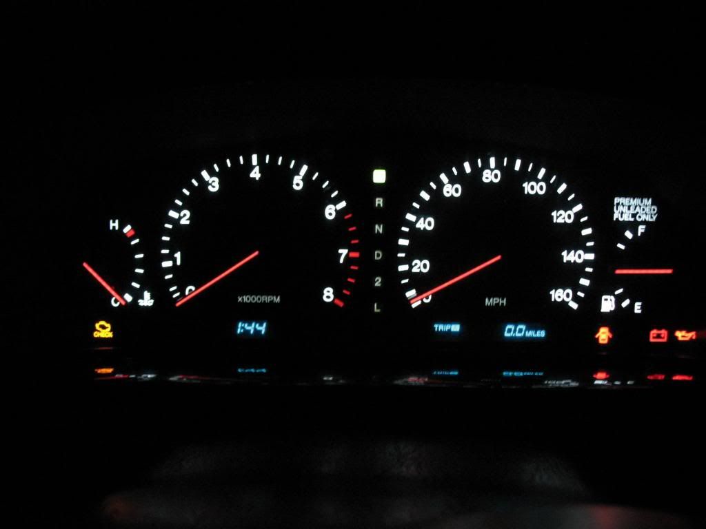
Well, since I have a new-to-me 1996 SC400 it's time to do another cluster anyway! My last one seemed to be about perfect but there were a few small changes I wanted to make. I'll post with updates later on, I have been experimenting with what may be a huge upgrade that can be done by most anyone. If my son's Mustang isn't eating up my entire weekend (again) I'll jump into this!
Last edited by Murco; 12-03-13 at 02:19 PM.
12-03-13, 09:39 PM
#27
NEEDLES -
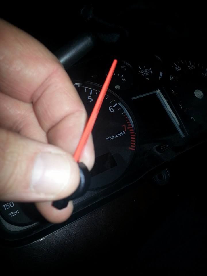
The factory needles, as we all know, eventually burn out. The quickest, easiest fix is getting needles from a 1995-96 SC as their red LEDs seem to last far longer. These are what I used on my first cluster (a 1992 car) and they were original needles from a high-mileage 1995 car, still in use to this day and working perfectly.
Another option, for those with soldering skills, is rebuilding your own with new micro LEDs. This YouTube video is great for those wanting to pursue this option...
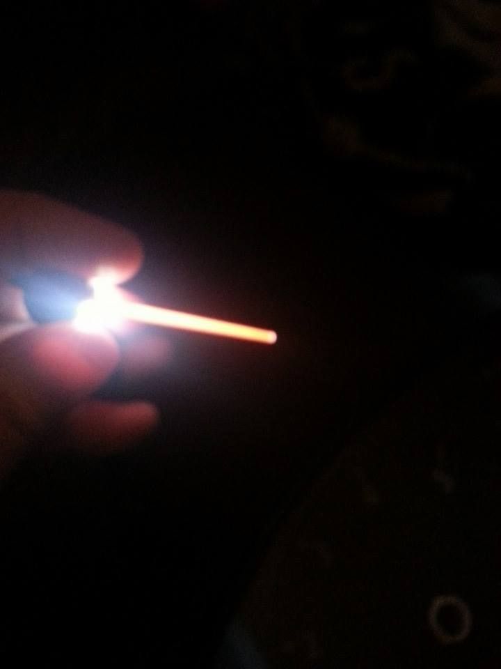
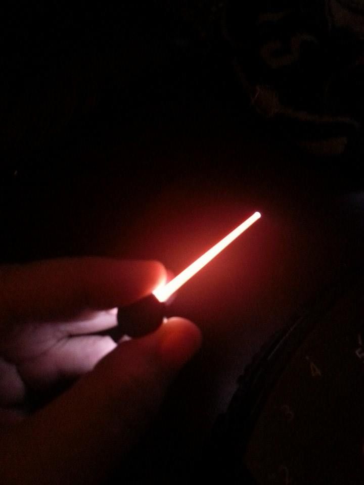
The option I have been experimenting with is using completely different needles from other cars. Here are the needles from an Audi A6. Notice that they are little more than clear plastic with a cap on the center and a dayglo-orange strip of paint on the bottom...

These needles light up by LEDs built into and shining up from the circuit board, the 2 LEDs are mounted on either side of the mounting pin...
Compare that last Audi needle photo with an OEM SC needle (with a burned out tip)...
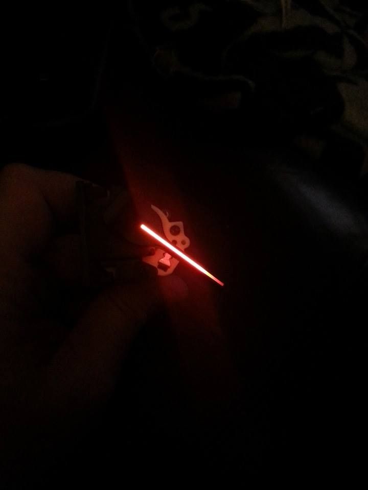
Using these needles would require removal of the clockspring and setting up and wiring 2 SMD LED's to light them but there would be significantly less weight on the motor and they would already be balanced as you do no modifications to them! Downside, they are about 1/8" shorter when mounted on the gauge....
The factory needles, as we all know, eventually burn out. The quickest, easiest fix is getting needles from a 1995-96 SC as their red LEDs seem to last far longer. These are what I used on my first cluster (a 1992 car) and they were original needles from a high-mileage 1995 car, still in use to this day and working perfectly.

Another option, for those with soldering skills, is rebuilding your own with new micro LEDs. This YouTube video is great for those wanting to pursue this option...
The option I have been experimenting with is using completely different needles from other cars. Here are the needles from an Audi A6. Notice that they are little more than clear plastic with a cap on the center and a dayglo-orange strip of paint on the bottom...


These needles light up by LEDs built into and shining up from the circuit board, the 2 LEDs are mounted on either side of the mounting pin...


Compare that last Audi needle photo with an OEM SC needle (with a burned out tip)...

Using these needles would require removal of the clockspring and setting up and wiring 2 SMD LED's to light them but there would be significantly less weight on the motor and they would already be balanced as you do no modifications to them! Downside, they are about 1/8" shorter when mounted on the gauge....
12-03-13, 10:33 PM
#28
GAUGE BACK LIGHTING -
This is the issue most experience first and the easiest fix is OEM bulbs and the blue covers. This gives you the proper brightness at night and is acceptable during daylight driving.
I mention brightness because that is the stumbling block for most LED conversions, most are far too bright. Your night vision is dependent on available natural lighting and things like poorly aimed HIDs lighting up the road too much and bright LED dash lighting make your pupils dilate significantly decreasing your ability to see distance and your peripheral vision. Next thing you know there is a deer's butt sticking out of your windshield and antlers giving you a nasal lobotomy!
I have an order for some different LEDs and resistors coming soon and I will be measuring the light output and lighting options when they come in. I'll post results as I do them!
Even with LEDs you can dim them somewhat but then you'll find your needles will dim at a different level. This happened with mine and on dark country roads I'd turn down the dash lighting and the needles would be much dimmer. The solution for both of this issues is circuit board lighting for both the needles and gauges
This is the set-up on the Audi, notice it's symmetry and the recess from the gauge face, about 1/2" back. The SC lamp housing has about the same distance one the ramps are removed and this makes a tremendous difference in regard to hot spots. The inner ring you see is for warning lamps and you can see one of the needle lights in the center.
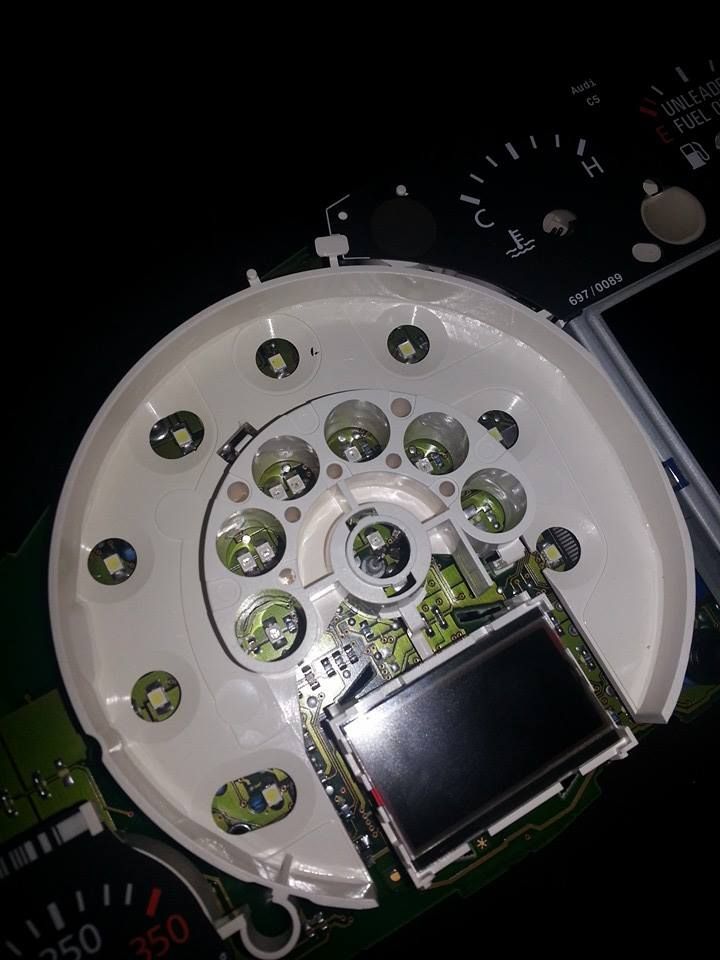
To replicate this design you will need to cut the ramps out of your factory cluster light panel and that's what I did on the cluster pictured above. The lights are SMD LEDs on a board I made with only the bulbs on it. The power came from the OEM lamp holders with contact inserts on them. I'd disassemble it for you to see but I just don't want to go through that when it's in and working perfectly. The original post on that cluster had someone insist the SMDs would dim in short order but they still work perfectly 2+ years on and have been through temperature ranges from -15 to over 100 degrees. If they last 3+ years before needing replacement I call that a win and the replacements are easy to make. I'll do it again and go step-by-step but this time I'm going to use slightly different LEDs that I want to experiment with first.
Stay tuned!!!
12-03-13, 10:50 PM
#29
NEEDLES -
The factory needles, as we all know, eventually burn out. The quickest, easiest fix is getting needles from a 1995-96 SC as their red LEDs seem to last far longer. These are what I used on my first cluster (a 1992 car) and they were original needles from a high-mileage 1995 car, still in use to this day and working perfectly.
Another option, for those with soldering skills, is rebuilding your own with new micro LEDs. This YouTube video is great for those wanting to pursue this option...
MBCluster - Lexus Instrument Cluster Needle and Backlight LED Upgrade - YouTube
The option I have been experimenting with is using completely different needles from other cars. Here are the needles from an Audi A6. Notice that they are little more than clear plastic with a cap on the center and a dayglo-orange strip of paint on the bottom...
These needles light up by LEDs built into and shining up from the circuit board, the 2 LEDs are mounted on either side of the mounting pin...
Compare that last Audi needle photo with an OEM SC needle (with a burned out tip)...
Using these needles would require removal of the clockspring and setting up and wiring 2 SMD LED's to light them but there would be significantly less weight on the motor and they would already be balanced as you do no modifications to them! Downside, they are about 1/8" shorter when mounted on the gauge....
