2JZGE Na-T TT Ecu Mod


 01-21-14, 10:21 AM
#1370

Yup vvti has a completely different connector. not even close to worth to the headache going between the 2 unless you have a vvti motorset. aristo ecu's are always around $100-150. check all the forum classifieds as well as supra forum classifieds if you have a high enough post count.
 01-29-14, 12:19 PM
#1372
You can use my tt ecu mod and use an n/a harness to run a gte, but you will have to go single turbo, or run the twins in TTC mode (not sequential).
to run the twins in sequential you would have to add the handfull of VSV's to the harness that control the wastegates and intake valves and all that jazz, you know the stuff that is on a GTE harness that wont be on a GE harness, and that is more of a pain and if you want sequential get a harness made, start with a gte harness, or research how to add all the vsv's.
if you can live with going single turbo which most do, or run the twins with no vsv's in TTC mode, then yes you can use my mod to run a gte motor.
for wiring a full gte swap, see Gerrb's thread in the build section he is still working on it.
https://www.clublexus.com/forums/bui...mkivs-144.html
there is also the aristo nightmare wiring thread and lots of info out there, start a thread in the performance section if you have gte motor specific questions this for the most part a na-t thread.
02-02-14, 03:22 PM
#1375
Driver
iTrader: (1)
Join Date: Jun 2003
Location: Washington
Posts: 194
Likes: 0
Received 0 Likes
on
0 Posts
any luck on the GTE trans wires?
i think ill do a gte auto since its already an auto car or a w58; i cant find a r154 kit for under $1000 anymore...shouldve done that when the prices on 154s were lower.
i think ill do a gte auto since its already an auto car or a w58; i cant find a r154 kit for under $1000 anymore...shouldve done that when the prices on 154s were lower.
02-03-14, 09:33 AM
#1376
To use the GE auto transmission, it will work plug and play but O/D light blinks when in overdrive.
I found there is a wiring difference on the no3 solenoid between the GE and GTE.
The GE trans does have a no.3 lock up solenoid ouptut and for some reason the pin location and signal is different.
good news is that you can wire this up even with your GE trans.
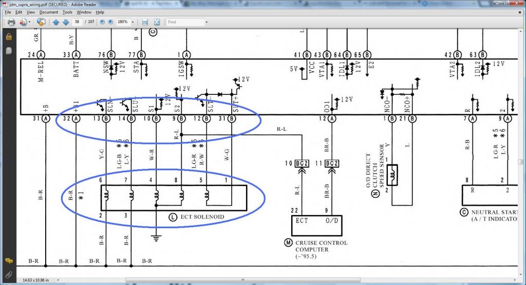
80 Pin Plug 14 SLU- Automatic Transmission No.3 Lock Up Solenoid Output
this pin 14 looks like it has a counterpart on the GE diagram on pin 8, but for the signal GE uses battery power to turn it on and gte uses ground to turn it on, so the wiring from ecu to solenoid is same just swap the pin from 8 to 14 @ ecu, and the other wire on the solenoid on the trans should be connected to 12v switched power now since the signal from ecu is now a ground. that should make the solenoid turn on correctly with the aristo ecu and there should be a connector nearby with switched power black/red wire you can borrow
To use a GTE Auto instead of the GE auto, do above and it looks like these extra pins are missing from the 2jzge pinout that need to be added because they are on the gte trans. ge trans does not have the need for the functions below.
pins 12, 13, and 31 on the 80 pin connector.
80 Pin Plug 12 SLT- Automatic Transmission Line Pressure Control Solenoid Output.
This needs to be added to harness like SLT+
80 Pin Plug 31 SLT+ Automatic Transmission Line Pressure Control Solenoid Output
This needs to be added to harness like SLT-
80 Pin Plug 13 SLN- Automatic Transmission Accumulator Back Pressure Solenoid Output.
This needs to be added to harness like SLT's. other wire on the SLN will get switched 12v black/red wire like we did for the no3 lockup solenoid
I just realized for those who are on automatics, wasnt the overdrive light blinking or something like that.
If the spot for the #3 lock up solonoid is different, then we could probably wire that up right and everything should work for you guys even on the GE auto trans. let me know what issues you auto guys are having I am interested in getting it worked out now.
*EDIT*
hope Gerrb doesn't mind I borrowed one of his diagrams that shows the gte diagram for these outputs.
You can see on GTE diagram how pin 14 goes to the solenoid, then goes to B-R which is 12v switched power.
On the GE pin 8 is for the same thing but it is setup like S1 and S2 (See gte diagram below) where the other side goes to ground, not switched power.
So besides moving the pin on the ecu, you need to change that second wire to 12v B-R wire, which you should be able to jump off the S1 and S2 solenoids as those are setup the same on a ge and gte.
I found there is a wiring difference on the no3 solenoid between the GE and GTE.
The GE trans does have a no.3 lock up solenoid ouptut and for some reason the pin location and signal is different.
good news is that you can wire this up even with your GE trans.
80 Pin Plug 14 SLU- Automatic Transmission No.3 Lock Up Solenoid Output
this pin 14 looks like it has a counterpart on the GE diagram on pin 8, but for the signal GE uses battery power to turn it on and gte uses ground to turn it on, so the wiring from ecu to solenoid is same just swap the pin from 8 to 14 @ ecu, and the other wire on the solenoid on the trans should be connected to 12v switched power now since the signal from ecu is now a ground. that should make the solenoid turn on correctly with the aristo ecu and there should be a connector nearby with switched power black/red wire you can borrow
To use a GTE Auto instead of the GE auto, do above and it looks like these extra pins are missing from the 2jzge pinout that need to be added because they are on the gte trans. ge trans does not have the need for the functions below.
pins 12, 13, and 31 on the 80 pin connector.
80 Pin Plug 12 SLT- Automatic Transmission Line Pressure Control Solenoid Output.
This needs to be added to harness like SLT+
80 Pin Plug 31 SLT+ Automatic Transmission Line Pressure Control Solenoid Output
This needs to be added to harness like SLT-
80 Pin Plug 13 SLN- Automatic Transmission Accumulator Back Pressure Solenoid Output.
This needs to be added to harness like SLT's. other wire on the SLN will get switched 12v black/red wire like we did for the no3 lockup solenoid
I just realized for those who are on automatics, wasnt the overdrive light blinking or something like that.
If the spot for the #3 lock up solonoid is different, then we could probably wire that up right and everything should work for you guys even on the GE auto trans. let me know what issues you auto guys are having I am interested in getting it worked out now.
*EDIT*
hope Gerrb doesn't mind I borrowed one of his diagrams that shows the gte diagram for these outputs.
You can see on GTE diagram how pin 14 goes to the solenoid, then goes to B-R which is 12v switched power.
On the GE pin 8 is for the same thing but it is setup like S1 and S2 (See gte diagram below) where the other side goes to ground, not switched power.
So besides moving the pin on the ecu, you need to change that second wire to 12v B-R wire, which you should be able to jump off the S1 and S2 solenoids as those are setup the same on a ge and gte.
Last edited by Ali SC3; 02-03-14 at 01:30 PM.
02-03-14, 01:28 PM
#1378
updated previous post with pictures and explanation.
I think for using the GE trans do the pin 14 > 8 and change the other wire from ground to 12V and everything should work perfect.
you could also use a relay like the a/c mod so when the ecu outputs ground the relay outputs 12v to the solenoid, then you wouldn't have to rewire the second wire at the trans solenoid, but who wants to wire up a relay with 5 or so extra wires when you can just cut the wire and jump to power at the trans which is what I would do.
for the gte trans you will have to wire up those extra couple pins as shown above and in the diagrams. mainly a few wires from the ecu to the solenoids, and the other side of solenoids get power or ground depending on which on so check the diagram, pretty easy if you think about it.
Last edited by Ali SC3; 02-03-14 at 01:32 PM.
02-03-14, 08:37 PM
#1379
Lexus Test Driver
Alright, guys, sorry to switch topics a bit, but I have an update on my car. It passed emissions today with the USDM TT ECU, so for anyone who has been wondering if it will or not, then the answer is YES!
Now, thats pretty much where the good news stops, because the car still runs pig rich at WOT and hesitates while boosting because it just dumps fuel. It idles at 1100 rpm, so it doesn't die out quite as often after pressing the clutch in right after letting off the throttle, but it still does it. My mechanic still recommends putting on a SAFC and leaning it out, but IDK if there is anything else that can help this problem besides this band-aid fix. Here is a pic of my engine bay:
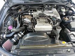
i have a manual boost controller that pegs the boost at 10psi. I have the BOV recirculated. TPS is good and healthy.
Does the fact that I'm running a small turbo (Sound Performance SP63) have anything to do with why my car is running like this?
02-04-14, 08:11 AM
#1380
Congrats on emissions, that is great news for the USDM crowd. wish it was running perfect but can't believe you passed with it running like that.. lol.
Your setup looks really clean btw really like the piping setup one of the cleaner ones I have seen lately.
no turbo size being smaller would help it run better in fact. no one else has had this issue so I am thinking this is maybe a 96/97 thing or USDM specific issue we haven't encountered yet.
what do you mean by pig rich? its normal to see afr's of 10-11 in boost on these ecu's.
It is a TT maf sensor and not the n/a one right?
I just remembered I think the US ecu uses 2 o2 sensors. pins 47 and 48, not just 48 like aristo ecu, how many do you have plugged in right now?
maybe that has something to do with it, 47 is the Sub o2 sensor and 48 is the main o2 sensor. maybe the sub one is just for the cat so not sure if that would do it.
that big vac line coming from the throttle body and going over the valve covers to the fuel rail, I think you may want to try deleting that and capping off both ends I have never seen that setup run the the na-t but maybe it works maybe it doesn't. something to test.
the vsv on the fuel pressure regulator, just bypass it with the vacuum hoses with a vac line straight from intake to fuel pressure regulator, that will solve any pin mismatch issues for the fuel pressure up vsv which is only for hot starts and is not needed at all, so lets just temporarily eliminate it by bypassing it with the vac lines, you can leave it plugged in electrical wise or unplug it also.
you can have the map sensor teed into the line, but be sure that when you do put the vsv back in the map sensor vac line is before the vsv, because the vsv can prevent vacuum from reaching the fuel pressure regulator when the signal is applied to it from the ecu, which it does when the engine is off on a hot start to raise the fuel pressure (by letting the FPU see ambient air and not the vacuum in the motor).
so putting your map sensor after this would be very bad, basically when the ecu decides to activate the vsv the it blocks the true reading from the fuel pressure regulator, and well if you had a map sensor after it, it would block some readings to it also, and I can't tell which part you teed into in the picture.
what did you do with the line from the passenger side valve cover breather. that line has to go to the intake pipe like your BOV if you still have the pcv in place on the drivers side or else you get unmetered air in the system.
also you have to make sure 100% that the bov is completely closed at idle on maf vehicles. if it cracks open even a bit you will have major issues like described. also keep in mind as the car warms up it pulls more vac so the bov may need adjustment if it is the adjustable kind like a tial to suit it for the varying vac readings.
looks like you are also missing the line for the power steering idle up that runs to the reservoir from the end of the intake. make sure there isnt a leak there.
Let me know if any of those things sound like they could be the issue or if you have tried them. Its gotta be something simple if you passed emissions it should be fairly close to running perfect I think there is just something small we are missing.
Last edited by Ali SC3; 02-04-14 at 08:28 AM.