2JZGE Na-T TT Ecu Mod


 07-18-12, 03:23 PM
#122

well six sense said the G- jumpering did help but he has a map sensor code now and an o2 sensor code.
getting a proper CEL seems bad but its actually really good, the o2 code is easily fixed and once the map sensor is fixed/rewired it should be running strong.
IF using JDM ecu with a map sensor, make sure when you are attatching your new map sensor you get the wiring colors right on both the map sensor and the old maf sensor wires if you are reusing those.
Also when reusing the maf wires, do not forget to move the maf signal wire at pin (B66) to the pin for MAP(B62) at the ecu connector
In the diagram it may not be 100% clear, but the air temp sensor and map sensor both have a wire going to ground.
the other temp sensor wire is the signal wire that goes to the ecu pin for the temp sensor.
the other 2 wires on the map are the signal wire that goes to the ecu (the one you moved to B62), and the other one is a +5v.
Last edited by Ali SC3; 07-18-12 at 08:15 PM.
07-18-12, 07:20 PM
#123
ok i kind of combined all the info in this thread into some veeeeeery crude diagrams. as i understand this is what all the wiring should look like if your putting in a jdm gte ecu with the ge harness and AEM 5Bar MAP & AIT sensors. if im wrong let me know
(the second one was the 1st one earlier, fixed it up a lil bit)
(the second one was the 1st one earlier, fixed it up a lil bit)
hey guys im wiring it up right now and wanna make sure, i just use this MAf wiring diagram for the iat and MAP the same orientation as if the maf were plugged in right?
07-18-12, 08:14 PM
#124
the wiring colors should match if you have an odb1 SC300.
if you have a newer SC then you may have a hotwire maf, and you're going to have to find a pinout to figure out which ones go where.
on that diagram you can tell by which sides the yellow/black is on and the other side will have the blue/red.
on the L-R wire for the map sensor, L is for Light Blue. I knew from my harness it was blue, but couldnt figure out why they named it L.
the MAP and IAT share a ground, not 5v.
Last edited by Ali SC3; 07-18-12 at 08:21 PM.
07-19-12, 05:15 AM
#127
gte & na-t
iTrader: (44)
Join Date: Jan 2007
Location: Maryland /Germantown
Posts: 5,139
Likes: 0
Received 7 Likes
on
7 Posts
95 has different color wires iirc, do go buy the color go by the pin location that was you know it's done properly!
More grounds really doesn't hurt anything , so i will just leave it alove if it's working fine, jz engines are finiky about grounds.
More grounds really doesn't hurt anything , so i will just leave it alove if it's working fine, jz engines are finiky about grounds.
07-19-12, 09:21 AM
#128
well six sense said the G- jumpering did help but he has a map sensor code now and an o2 sensor code.
getting a proper CEL seems bad but its actually really good, the o2 code is easily fixed and once the map sensor is fixed/rewired it should be running strong.IF using JDM ecu with a map sensor, make sure when you are attatching your new map sensor you get the wiring colors right on both the map sensor and the old maf sensor wires if you are reusing those.
Also when reusing the maf wires, do not forget to move the maf signal wire at pin (B66) to the pin for MAP(B62) at the ecu connector
In the diagram it may not be 100% clear, but the air temp sensor and map sensor both have a wire going to ground.
the other temp sensor wire is the signal wire that goes to the ecu pin for the temp sensor.
the other 2 wires on the map are the signal wire that goes to the ecu (the one you moved to B62), and the other one is a +5v.
07-19-12, 12:23 PM
#129
not sure yet he is getting back to me, he was throwing the code for the map sensor.
I got that code also, and for me I had the signal wire and one of the other wires mixed up on the map sensor connector (found out by checking with the voltmeter), swapped em out and has worked fine since.
thanks Omar for the wiring info, go by pin locations if your colors are different.
you can also look at those spots on the ecu connector where the signals are supossed to go and see what the respective wire colors are.
they will be the same color at the ecu and at the maf plug.
so pay attention when making that wiring connection exactly like the diagram both at the old maf plug and at the new map sensor connector, and move pin at ecu from wherever your maf signal comes in (odb1 is b66) to map sensor spot (all JDM GTE are b62).
sounds hard and it can be the first time, but I'm telling you guys its worth it. keep at it.
The following users liked this post:
MrGi11 (12-29-20)
07-19-12, 01:10 PM
#130
not sure yet he is getting back to me, he was throwing the code for the map sensor.
I got that code also, and for me I had the signal wire and one of the other wires mixed up on the map sensor connector (found out by checking with the voltmeter), swapped em out and has worked fine since.
thanks Omar for the wiring info, go by pin locations if your colors are different.
you can also look at those spots on the ecu connector where the signals are supossed to go and see what the respective wire colors are.
they will be the same color at the ecu and at the maf plug.
so pay attention when making that wiring connection exactly like the diagram both at the old maf plug and at the new map sensor connector, and move pin at ecu from wherever your maf signal comes in (odb1 is b66) to map sensor spot (all JDM GTE are b62).
sounds hard and it can be the first time, but I'm telling you guys its worth it. keep at it.
I got that code also, and for me I had the signal wire and one of the other wires mixed up on the map sensor connector (found out by checking with the voltmeter), swapped em out and has worked fine since.
thanks Omar for the wiring info, go by pin locations if your colors are different.
you can also look at those spots on the ecu connector where the signals are supossed to go and see what the respective wire colors are.
they will be the same color at the ecu and at the maf plug.
so pay attention when making that wiring connection exactly like the diagram both at the old maf plug and at the new map sensor connector, and move pin at ecu from wherever your maf signal comes in (odb1 is b66) to map sensor spot (all JDM GTE are b62).
sounds hard and it can be the first time, but I'm telling you guys its worth it. keep at it.
I see what goes where on the harness side but wanna make sure im putting them in the right MAP pins.
Last edited by sj408; 07-19-12 at 01:27 PM.
07-19-12, 01:30 PM
#131
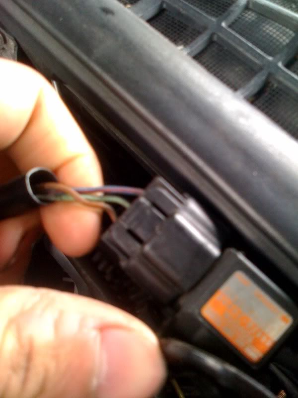
looking at the back of map sensor connector (where the wires come out) with tab up, it is:
on left (+5v - light blue/red ); in the middle (signal - green/black); on the right (ground - brown).
If your maf wire colors matched with those on the first page, you may notice the 2 power and ground wire colors are the same color as the map sensor wires (i did not have an original map sensor connector so i never noticed that before).
when you get it right, with the key on engine off, the signal wire should be around 2.x volts.
the x will change a little depending on your altitude but somewhere in the low to mid 2v range.
I found this picture on the web so you can see the colors
Last edited by Ali SC3; 07-19-12 at 01:36 PM.
07-19-12, 05:57 PM
#132
ITS ALIVVVVVVVVVVVVVVVVVVVVVVE.
So got it started, it idles GREAT. revs out smooth but when you hold a constant rpm it breaks up a bit, i also had the map wired up wrong so well see if correcting it changes.
also with the 520cc injectors im running it seems to be running pig rich, thats fine by me ill just get a cheapy used AFC and correct it injector wise.
ill take a vid when i get a chance and test drive thsi thing to let you guys know how it works with my auto trans
07-20-12, 12:14 PM
#135