2JZGE Na-T TT Ecu Mod
 12-30-12, 06:03 PM
#841
I got a 0-5 signal to the ecu by running a new wire, but for some reason both the IDL wires at the ecu have power when there is no connection to the TPS,
The IDL circuit is backwards, probably because I had to reverse the polarity for the TPS to read correctly.. Weird.
I adjusted the timing to 7* and it still idles up. Any ideas?
The IDL circuit is backwards, probably because I had to reverse the polarity for the TPS to read correctly.. Weird.
I adjusted the timing to 7* and it still idles up. Any ideas?
 12-31-12, 07:52 AM
#842

Yeah that's what I was trying to tell you about idl. You only swap the outer 2 pins I thought or in some cases you swap all 4. So basically from where you have it now try swapping back the inside 2 pins and that should fix idl.
Outside pins are voltage and ground if I remember correctly and it sounds like those are correct now if you get the 0-5v happening.
Outside pins are voltage and ground if I remember correctly and it sounds like those are correct now if you get the 0-5v happening.
12-31-12, 08:37 AM
#843
5v-VTL-IDL-E2
I swapped the outside pins to reverse the polarity, and it works correctly, but for some reason IDL shows 11-12v closed and 0 when I open the throttle.
So VTL works correctly, but IDL is backwards.
Does the ECU power the IDL wire until it's grounded in the TPS?
I got it to idle nicely, since I found a huge vacuum leak!
Last edited by spoolxexo; 12-31-12 at 08:41 AM.
01-03-13, 10:15 AM
#845
Ok so it looks like you have to flip all 4 wires, not just the outer 2.
I know the n/a TPS is the same as the tps on the trac control on a 2jzgte, so you can tell from below that all 4 wires switch positions between the main tps (gte throttle body) and the sub tps (GTE trac and n/a throttle body).
I never had this problem because the q45 throttle body uses the n/a tps, which I didn't have to rewire anything on from stock.
that leads me to believe that the only wiring that needs to be done is at the tps itself.
you can see the GTE tps goes E2, IDL, VTA, VC
and the ge TPS goes VC, VTA, IDL, E2.
I helped a friend out with a 1.5JZ running on a ge harness on an AEM, and I just swapped the outer 2.
AEM does not use IDL, so I never confirmed that was working or not, but I would imagine just match the wiring below for the sub TPS.
hope that helps.
you should get IDL continuity when its closed, and its open circuit as soon as you blip the throttle.
they never state the voltage range thats on it, its more of a resistance check for continuity.
Last edited by Ali SC3; 01-03-13 at 10:26 AM.
01-03-13, 02:26 PM
#847
5v-VTL-IDL-E2
I swapped the outside pins to reverse the polarity, and it works correctly, but for some reason IDL shows 11-12v closed and 0 when I open the throttle.
So VTL works correctly, but IDL is backwards.
Does the ECU power the IDL wire until it's grounded in the TPS?
I got it to idle nicely, since I found a huge vacuum leak!
I swapped the outside pins to reverse the polarity, and it works correctly, but for some reason IDL shows 11-12v closed and 0 when I open the throttle.
So VTL works correctly, but IDL is backwards.
Does the ECU power the IDL wire until it's grounded in the TPS?
I got it to idle nicely, since I found a huge vacuum leak!
seems different than what you have written above unless we are reading from different sides.
Here is what is happening with the harness and sensor side of IDL:
http://www.youtube.com/watch?v=XJ2_BmVlUkQ
http://www.youtube.com/watch?v=XJ2_BmVlUkQ
try the pin combo above, that hunting up and down is what the ecu does when it gets confused, mine used to do that when I had the wrong map sensor I wouldn't worry about it. while you are making continuity by grounding it the level will be incorrect, resistance will look too low like a short.
If all the wiring is correct, which it is or backwards depending on the side you are reading from, My only guess is that your tps isn't turned far enough to give continuity on IDL when its connected because when you disconnect it it should have open continuity and i would imagine some type of change would occur. leave everything connected and try moving the pins back around as listed above if they are not right.
If its right I know it sounds crazy but you may just need to turn your tps some more.
Mine won't even stay running if I turn it just a little past where it is set right now.
I wish I could go back in time to when the Toyota engineers proposed the signals IDL and IGF and tell them what I think of their evil creations
 .
.btw what happens when you rev it with the IDL connected. It sounds like it idles and revs fine with it completely disconnected.
with it connected it sound like its idling just fine, just a little bit of a high idle but clearly the IACV is working. does it rev the same connected as disconnected?
maybe that FFIM is letting in some outside air into the runners? I know you prob don't want to hear that and I hope that isn't the case we will be troubleshooting for a while.
Last edited by Ali SC3; 01-03-13 at 02:40 PM.
01-03-13, 02:56 PM
#848
Driver School Candidate

Join Date: Jul 2012
Location: tx
Posts: 45
Likes: 0
Received 0 Likes
on
0 Posts
my car has been running great the past 2 months boosting just 9 pounds t be safe. Then I decided to adjust my intake pipe a little bit because it was rubbing slightly against my iat sensor. apparently when I did that I pulled on my map sensor ground wire to hard and one of my electrical taped connectors came apart insid the tape. gotoleave 30 minutes later and car starts stutters then dies. checked voltage found the problem and found that now the sensor is fried. again.
be extremely carefulwith the map sensors. apparently they are not as tough as we thought
be extremely carefulwith the map sensors. apparently they are not as tough as we thought
01-03-13, 03:52 PM
#849
That almost seems unfair how easily they can be grounded out.
I got lucky I soldered all the wires and had it all done before I plugged it in.
I'll make a note on the first page when I get a chance.
Make sure to solder this time, don't use those butt connectors they are no good for this type of stuff.
I got lucky I soldered all the wires and had it all done before I plugged it in.
I'll make a note on the first page when I get a chance.
Make sure to solder this time, don't use those butt connectors they are no good for this type of stuff.
01-03-13, 06:56 PM
#850
If all the wiring is correct, which it is or backwards depending on the side you are reading from, My only guess is that your tps isn't turned far enough to give continuity on IDL when its connected because when you disconnect it it should have open continuity and i would imagine some type of change would occur.
btw what happens when you rev it with the IDL connected. It sounds like it idles and revs fine with it completely disconnected.
with it connected it sound like its idling just fine, just a little bit of a high idle but clearly the IACV is working. does it rev the same connected as disconnected?
with it connected it sound like its idling just fine, just a little bit of a high idle but clearly the IACV is working. does it rev the same connected as disconnected?
When I ground out the IDL on the ECU side, completing the circuit, it won't rev up at all.
No EGR, IACV delete plate.
So I read this whole thread again and when Ishgootstuff's TPS problem came up it was almost the same symptoms.
You mentioned that the Distributor could be off a tooth causing a more advanced condition then wanted, and thus the idle goes up.
I should also mention, that the Header gets cherry red, idling.
01-03-13, 09:08 PM
#851
seems like its not any of the simple stuff.
distributor could have something to do with it it would have to be very retarded to cause the cherry red headers at idle, you should hit it with a light if you haven't done that yet. usually being retarded lowers the rpm's though. If you were really advanced it wouldn't sound very good.
I still don't know how far it is off initially cause I was on a standalone previously and had moved my dizzy several times.
remember at those rpm's it will be higher than the base timing but just keep it in a safe range for the load and rpm you are at.
just from the sound it seems like you are easily 2k+ rpm's.
did you mean you have a IACV delete plate as in you are running no idle air control valve?
that makes things more confusing because you shouldn't have nearly enough air to get an idle like that, unless your throttle body is cracked open a significant amount which is unusual.
hot headers can also be an indication of a bad air fuel mixture. do you have an air fuel gauge? its can be hard to tell if its way too lean or way too rich without one. it could be getting extra air from somewhere, or it could be a faulty injector, or a bad sensor even.
back when I had no IACV I had to crack my q45 throttle body a decent amount to get a decent cold idle, which is like 1000-1200 rpms.
Last edited by Ali SC3; 01-03-13 at 09:15 PM.
01-04-13, 11:17 AM
#852
Driver School Candidate

Join Date: Jan 2013
Location: UK
Posts: 8
Likes: 0
Received 0 Likes
on
0 Posts
Hey Guys.....Top thread!
Ive been reading and understanding this thread for a while, am currently in the process of fitting a JDM TT ECU into my NA....Im also goin down the route of fitting the TT FFIM along with the TT throttle body and sensors.
With regards to the TPS issue these diagrams might help to
GTE TPS wiring
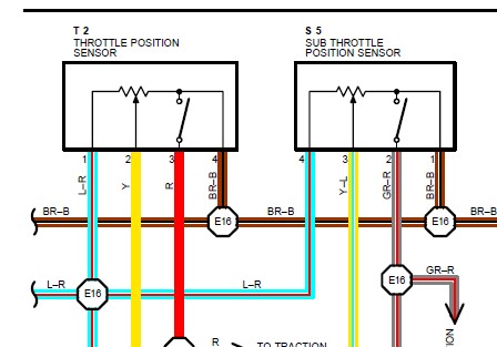
and GE TPS wiring
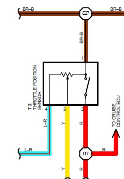
Ive been reading and understanding this thread for a while, am currently in the process of fitting a JDM TT ECU into my NA....Im also goin down the route of fitting the TT FFIM along with the TT throttle body and sensors.
With regards to the TPS issue these diagrams might help to
GTE TPS wiring
and GE TPS wiring
01-04-13, 05:35 PM
#854
thanks for the diagrams its always nice to have it in one place.
In the UK is your car already map based? good luck with the project.
I don't recommend using the TT intake on a na-t. everyone who has done it so far has had issues.
If you are willing to make it work go for it but an aftermarket or DIY ffim may be more worth the effort.
In the UK is your car already map based? good luck with the project.
I don't recommend using the TT intake on a na-t. everyone who has done it so far has had issues.
If you are willing to make it work go for it but an aftermarket or DIY ffim may be more worth the effort.
01-05-13, 04:58 AM
#855
Driver School Candidate
Join Date: Jan 2013
Location: UK
Posts: 8
Likes: 0
Received 0 Likes
on
0 Posts

thanks for the diagrams its always nice to have it in one place.
In the UK is your car already map based? good luck with the project.
I don't recommend using the TT intake on a na-t. everyone who has done it so far has had issues.
If you are willing to make it work go for it but an aftermarket or DIY ffim may be more worth the effort.
In the UK is your car already map based? good luck with the project.
I don't recommend using the TT intake on a na-t. everyone who has done it so far has had issues.
If you are willing to make it work go for it but an aftermarket or DIY ffim may be more worth the effort.
Ali whats the main issues others are having with the TT FFIM??....The way Ive planned to do it is with having the TT lower runners modified to fit the GE head so the rest of it is plug and play, and that way I can also use the TT fuel rail and injectors. Ive bacially planned it so that Im using everything TT based, FFIM, throttle body, Injectors, IAC, ECU the lot. So the only thing left GE will be the internals and head. My project thread is on a different site, once I get a bit closer to start up I will put up the link.
One question I do have, will I need to also change the stock NA fuel pump and fuel pump ecu to a TT one also to get it to fire up?