2006 RX400h Timing Belt and Water Pump Replacement
 01-27-13, 08:28 AM
#1
Driver School Candidate
Thread Starter

Join Date: Aug 2003
Location: North Carolina
Posts: 11
Likes: 0
Received 0 Likes
on
0 Posts
I recently replaced my timing belt, water pump, belt tensioner and upper and lower pulleys. Hopefully this post will help others who choose to take this project on. I’d like to thank thomas1 for some assistance via DM during my endeavor, luvrxxx for instructions on making the SST substitute to hold the harmonic balancer steady, and others that have posted tips on the board.
So how was it? A royal PITA! Would I do it again? At least once more, just to see if I learned anything the first time – I sure hope I did. How long did it take? Well, if I had to do it again I think I could do it in 6-8 hours. But I must admit that I started this project on a Saturday and didn’t get done until . . . . Thursday! What?!
  That wasn’t non-stop of course, but after Saturday and Sunday it was still 8 hours more to finish. Mostly due to areas where I got stumped for a bit. Is this my first time working on a car? No. But, I have only done more-involved repairs on BMW inline six engines before. Even there, jobs with 4-6 hours of disassembly/assembly are not too bad on that engine. This was a lot tougher, but most of my obstacles/delays can be avoided.
Parts-
I purchased the timing belt, tensioner, water pump and gasket from Sewell Lexus. Excellent prices through the Club Lexus link. I bought the upper and lower pulleys from another vendor.
I would recommend buying two stud bolts (the one that shears off in the Youtube video) so you can reinstall them w/o the stud extractor near the end. The P/N is 90126-08012. They were $4.56 each. I had one new one, which worked fine, since I didn’t try the second one after the first one sheared off.
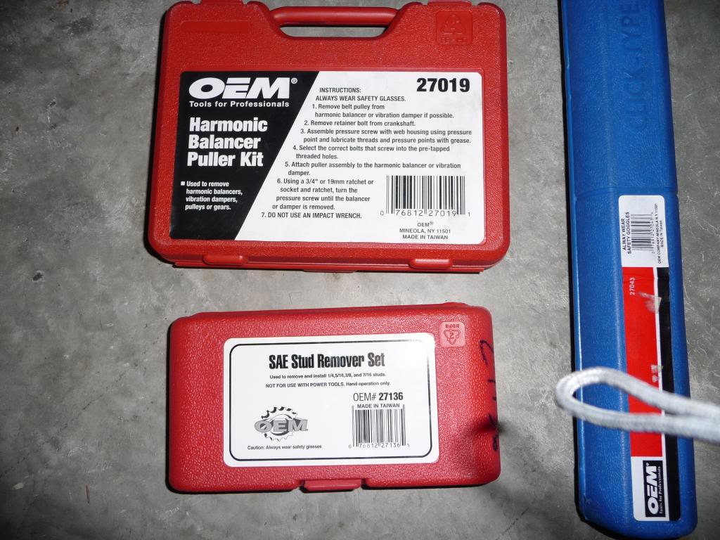
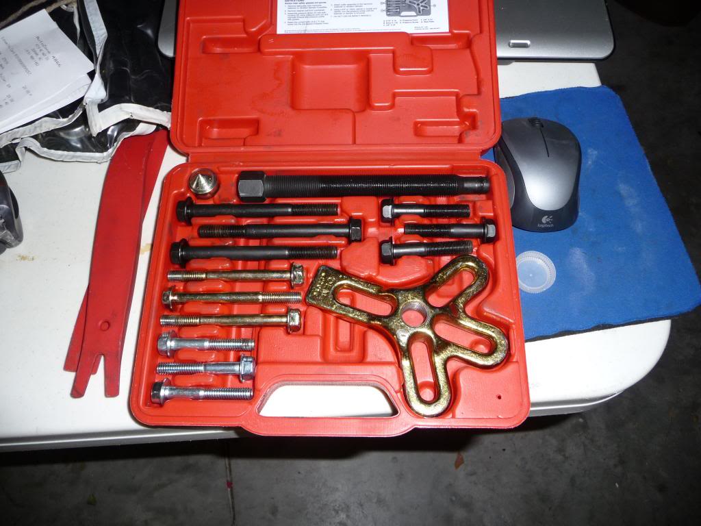
I made the SST tool, but could not find any channel-shaped metal. I bought a 3/16 in X 2 in X 3 ft steel strap from Lowes that worked fine. Also on hand I had three tools from Autozone – a harmonic balancer puller, a stud remover kit (only SAE was available) and a higher force torque wrench. If you can find a metric stud remover, use that, as I think it might grip the stud bolt better (more on that later). But that’s just a hunch.
Videos/documents –
I also used the instructions posted in this thread - https://www.clublexus.com/forums/hyb...new-owner.html
They were right for the most part. I will refer to some steps in the instructions on occasion where I found discrepancies.
The youtube video on the 300RX was somewhat helpful (i.e., realfixesfast), but there is much less area to work in between the wheel well and the timing belt due to A/C and other lines that can’t be moved. I think the best benefit of that video is that I was prepared if the stud bolt tip sheared off (it did) so I had the extractor on hand and was ready to jack up the engine (did that too).
Removing components to get access -
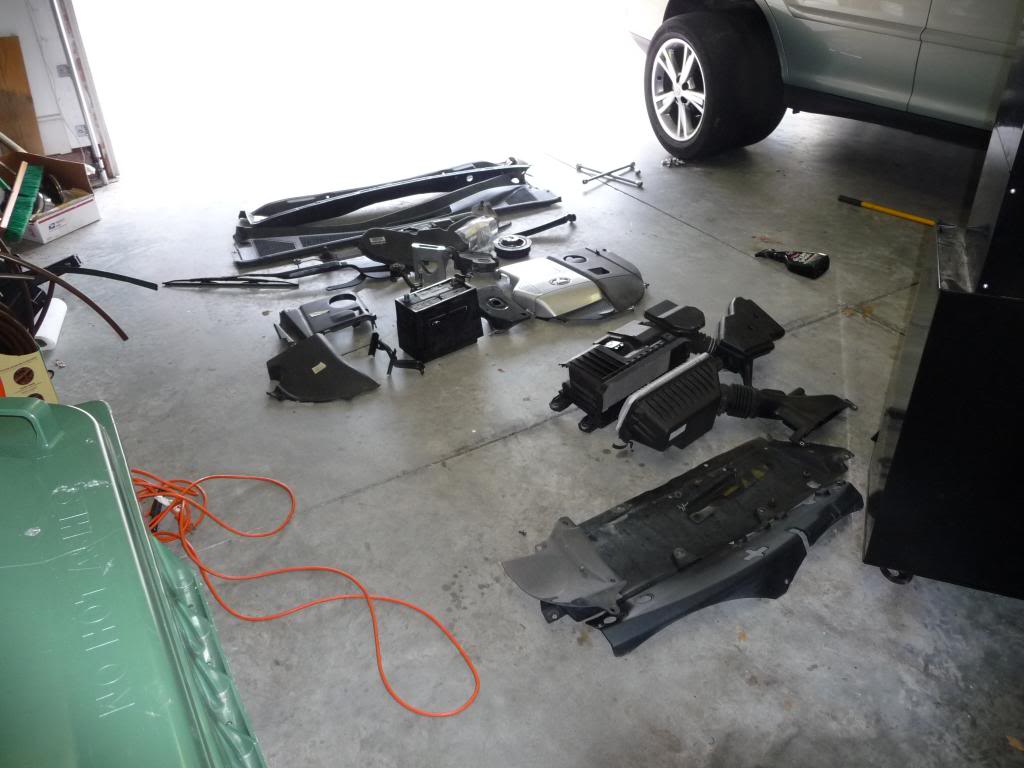
The steps through removal of the wiper assembly and cowl; the air cleaner case and resonator; and brackets around the brake master cylinder are pretty straight forward, and should take between 1 and 2 hours if you’re taking your time and keeping track of everything. As noted by Thomas1 earlier, there is no alternator or power steering pump to mess with on the 400h. You do remove the battery and supports (very simple) and some brackets for the master cylinder. This is a photo of what’s removed in the early stages. A lot of it is covers on top of, or under, the engine though.
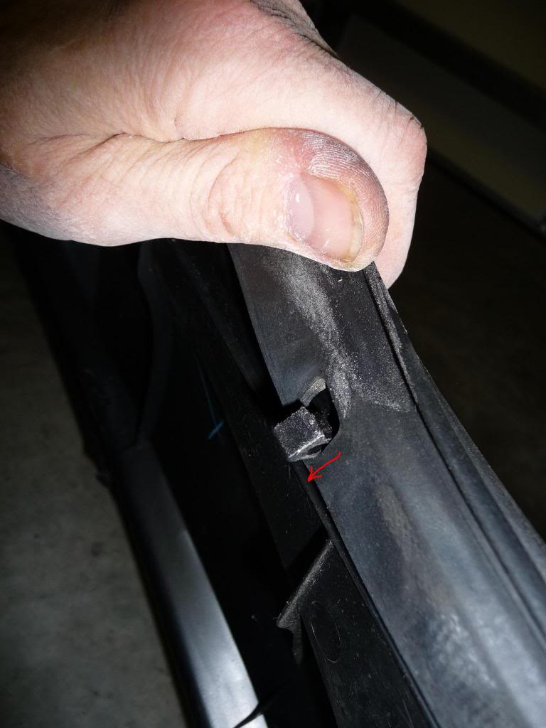
This is a photo of the clips under the rubber trim for the cowl. You push the tabs toward the windshield and then they pop up.
Timing belt Area –
This is where things got a bit tougher –
Step 22 (they forgot to label the step though) of the instructions is where the pulley (i.e., harmonic balancer) bolt is loosened. The SST is used for that. The pulley bolt takes a 22 mm socket (I didn’t have one on hand). It is also important to have enough washers on the two SST bolts to fill the area from the holes in the pulley to the bottom of the SST. If not the bolts may bend.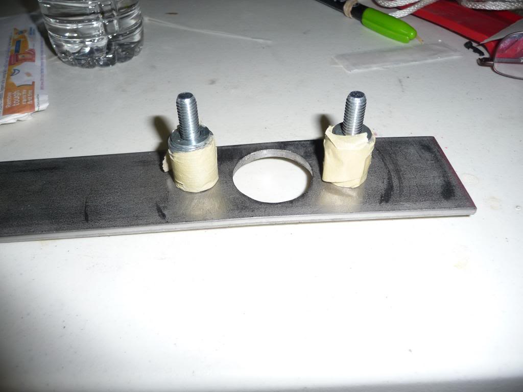
Problem 1 – My 18 inch breaker bar was insufficient to loosen the pulley bolt. I then bought a 3 foot section of half inch steel pipe to slide over the breaker bar. This ended up bending the bolts in the SST (see previous discussion). That meant buying new bolts and more washers (see explanation above). Once I got the SST back together I had the bolt loose in one minute. I spent 3 hours messing with that, when it could have been 5 minutes if I had my act together better.
The other advice I can give is to install the SST so it points in the 9 o’clock direction. That way it stops moving via its CCW rotation at the bracket for the left engine mount. You may have to turn the pulley CLOCKWISE a bit so the two bolt holes where the SST is threaded align the right way (horizontal for the most part).
Once the pulley bolt is out you use the Autozone puller tool and remove the pulley. The bolts with Autozone’s puller tool were too long but I used the SST bolts instead to mount the puller to the pulley. Make sure you oil the threads of the remover bolt (the one in the center of the puller) as that eases removal.
Next remove the four 10 mm bolts on the lower timing cover.
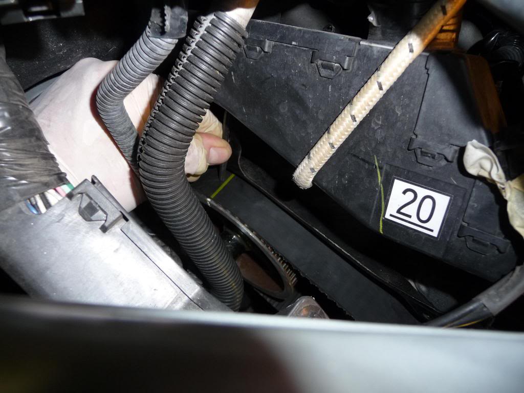
For the upper cover you remove some small clamps for a wiring harness that runs on top. The tabs push toward the passenger side and lift up. Then remove the five 10 mm bolts for the upper cover.
Step 25 – Remove the side engine mounting bracket. (Note-this photo is posted to show the nuts on the stud bolts. The harmonic balancer won't be present when you are at this step in the procedure. )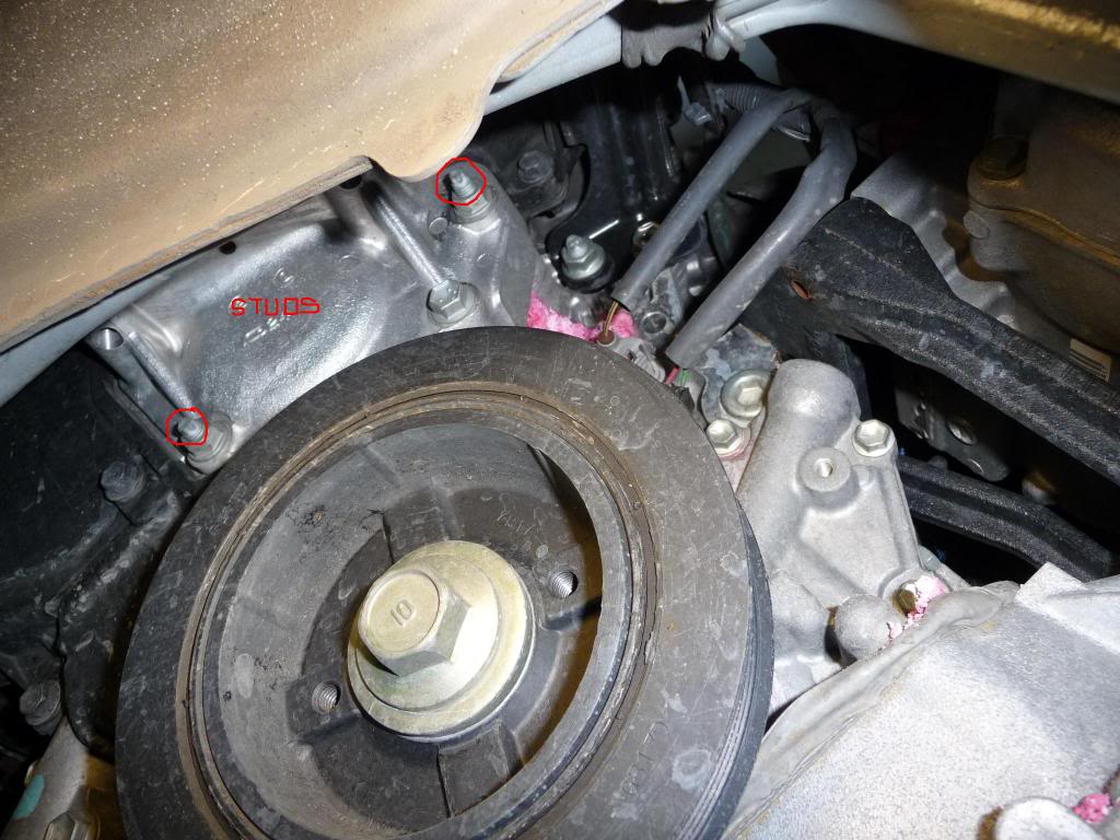
Problem 2 – as the youtube video shows, the stud bolt torx threads can shear off (marked in the photo above). The first one I tried sheared off. That meant raising the engine to slide the bracket off the studs. I read where someone said you could leave that bracket, but I don’t see how to replace the timing without removing it. I had water pump leakage anyway so the bracket had to come off anyway.
Took about 2-1/2 hours to loosen bolts on the engine motor mount bolts (the video shows loosening only one, but I had to remove bolts on all three), lift the engine, slide the bracket off the studs and then remove the studs with the extractor tool. I used the 5/16 inch stud extractor in the kit. The extractor would slip about 90 degrees each rotation before it gripped and started to rotate the stud. The � inch extractor was too small to even slide down the bolt. When the studs first broke loose the sound was so loud that I was certain I had snapped the stud bolt. Surprisingly that was not the case. I can’t imagine the torx threads holding up enough to remove them with the E8 inverted torx socket though.
One thing that would speed up stud extraction would be a 21 mm ratcheting combination wrench to put on the end of the extractor since it was a PITA to turn the extractor with a fixed wrench each time and remove and reconnect. There is not enough room to get a socket over the stud extractor. In addition, I found the only way I could get the bracket out was to move one of the A/C lines out of its holder bracket in the back and unbolt an attachment near the battery tray in the front. That allowed me enough wiggle room to get the bracket out.
I followed the procedure in the instructions covering removal of the timing belt. I should note that in step 27.c., where you are advised to rotate the CRANKSHAFT 60 degrees CCW, that the degrees of rotation for the CAMSHAFT pulleys will only be about 30 degrees, not 60 degrees, due to the size of the pulleys and number of teeth (24 at the crankshaft and 48 at the camshaft). I put some whiteout on the camshaft timing marks and the marks on the rear timing cover to see them better. The rear one is very hard to see though.
Rear (this is with everything out of the way – not much room!) -
Front pulley:
Water Pump –
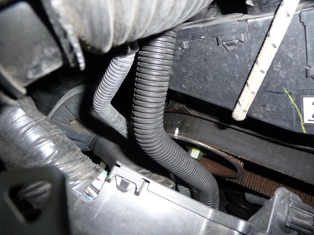
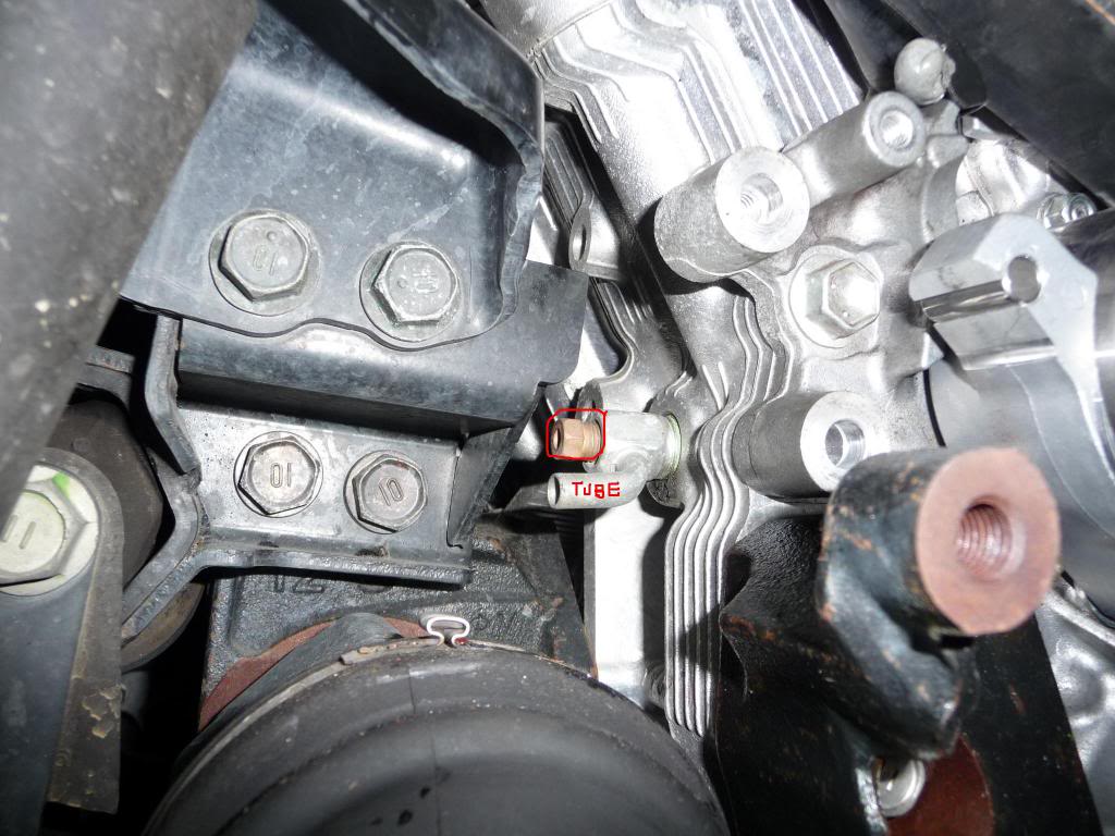
It took about an hour to drain the coolant. I got out about 6 quarts in total - 4 from the radiator, 2 from the front engine block drain (just to the right of the oil filter) and zero from the rear engine block drain (located above the right engine mount – see photo).
The water pump and gasket came out easily after removing the nuts.
For installation, I wasted about � an hour trying to squeeze the new water pump under the rear timing cover and in place, but just couldn’t get it right. I then used the leftover 2-foot steel section, from making the SST tool, and inserted it down behind the rear timing cover, as shown in the youtube video. I had the water pump installed in about a minute after that . . . very little fiddling required that way.
Timing Belt Installation –
After installing two new idler pulleys it was time to install the timing belt. This was tougher than I expected since I didn’t realize the rear Camshaft pulley wants to jump forward while the front Camshaft pulley tries to jump backward. What fun! I was able to stabilize the rear pulley with a socket on a breaker bar and the front with a combination wrench, with the timing marks aligned.
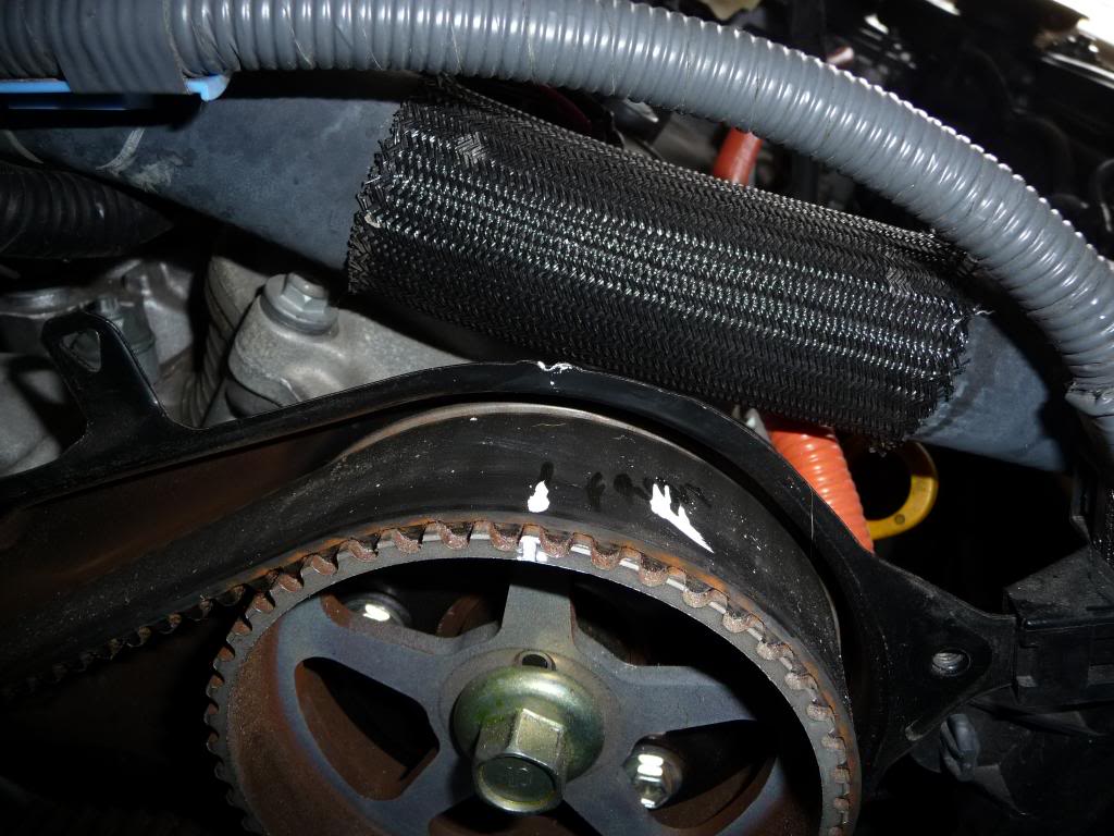
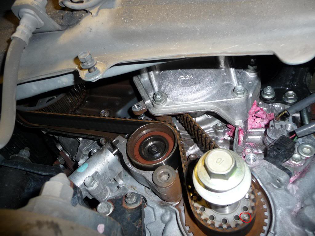
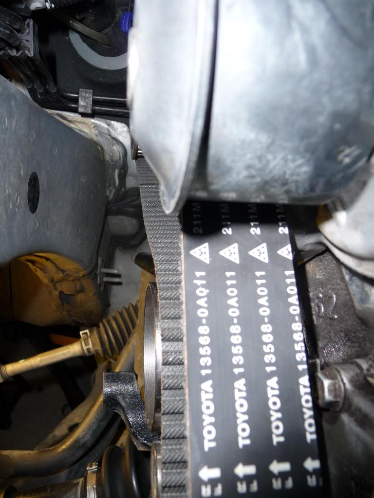
If you buy a Toyota timing belt, which I’d highly recommend, it will have marks on it that align with the three timing pulley marks. Two marks are solid lines that align with the Camshaft pulley marks and the third mark is a dotted line that aligns with the Crankshaft pulley. This dotted line matches up with a round mark at around the 3 o’clock position on the Crankshaft pulley (i.e., not the TDC mark that’s at 12 o’clock). It’s shown in the photo below, but a bit fuzzy.
(Note: the timing marks were not at TDC when the above photo was taken.) I found it best to first line up the dotted mark on the belt with the Crankshaft mark “dot”, then go clockwise to the front Crankshaft, and lastly to the rear. If you have it right all three belt marks should align with corresponding marks on the pulleys and those marks will align with the timing marks on the engine/timing cover as well.
Example of the rear pulley with belt mark –
Belt Tensioner Installation –
Problem 3 – I thought I had everything lined up at this point with the new belt in place. The next step is to install the belt tensioner. However, when I went to install the tensioner (it is in a different location than the RX300 in the video), I did not have enough “slack” in the belt to allow the lower idler pulley to align with the bolt holes on the engine. The youtube video didn’t indicate any effort for this step, so I wasn’t sure what to do. Did I need more force? Did I have something in the wrong place? After checking everything twice, I called some mechanics and DM’d some folks on the board, but couldn’t figure it out. I wasted several hours scratching my head over this issue.
I finally called a mobile auto repair guy that came by. He said everything looked fine except the rear timing mark was one tooth forward, though the belt was lined up with the pulley mark. After fiddling with that for about 10 minutes we had the rear pulley adjusted properly and just that amount of rotation allowed enough additional slack in the belt to get the tensioner installed.
I turned the crankshaft through two revolutions and the timing marks on the pulleys lined up with the rear timing cover marks. They lined up! I did not experience any issues with the pulley jumping once the tensioner pin was pulled.
  After rotating the crankshaft the marks on the belt don’t line with the pulley again– due to the number of teeth not matching two rotations of the pulley.
Note: The mechanic suggested using the black, paper binder clips to hold the belt on the timing pulleys. He used a beefy spring clamp on the front pulley There was not any room to get zip ties behind/around the pulleys and belt.
Reassembly -
Things were pretty straight forward using the instructions . . . a few things to note.
Coolant refill – this is a slow process. I found that massaging the upper radiator hose helped get coolant into the system faster but it still took an hour to get a bit over 4 quarts in. I didn’t get all 6 quarts back in until the engine had been run a few minutes and the heater set on maximum.
Timing belt covers – make sure you follow the order of steps in the installation instructions. The side engine bracket needs to go on before the covers can be installed. If you raised the engine to slide the bracket off the broken stud bolt, then you need to: 1) put the two stud bolts in, 2) slide the engine bracket over the studs, 3) install the bolts for the bracket and two nuts on the end of the studs (21 ft lbs), 4) lower the engine, 5) then put the covers on (75 in-lbs all around). There is not enough clearance under the A/C line to install the upper timing belt cover when the engine is still raised – took me another � to realize that was my problem there.
Notes: I could not get access to the front engine motor mount nut from above since I lacked an 18 inch ratchet extension, so I removed the nuts from below the frame instead – I believe there were three. If you go that route, make sure the motor mount bolts line up with the holes in the frame when you lower the engine.
.
Step 14 - It will be obvious, but the installation steps are actually for removal of the air cleaner case, not installation.
Step 17 – I only had 4 carrier bolts for the battery tray, not 5 mentioned.
Step 21 – they don’t tell you in the instructions that the cowl top ventilator needs to be installed before the wiper arms go in. It just jumps straight into the wiper arm installation. I didn’t go past Step 27 but the car ran fine.
You will need to reset the power windows and sunroof once you're done and the battery is hooked up. The owners manual has the steps. Mine was on page 45.
Hopefully this will be helpful and save others some time. I will try to answer any questions others may have. Good luck!
Greg.
So how was it? A royal PITA!
Would I do it again? At least once more, just to see if I learned anything the first time – I sure hope I did. How long did it take? Well, if I had to do it again I think I could do it in 6-8 hours. But I must admit that I started this project on a Saturday and didn’t get done until . . . . Thursday! What?! That wasn’t non-stop of course, but after Saturday and Sunday it was still 8 hours more to finish. Mostly due to areas where I got stumped for a bit. Is this my first time working on a car? No. But, I have only done more-involved repairs on BMW inline six engines before. Even there, jobs with 4-6 hours of disassembly/assembly are not too bad on that engine. This was a lot tougher, but most of my obstacles/delays can be avoided.Parts-
I purchased the timing belt, tensioner, water pump and gasket from Sewell Lexus. Excellent prices through the Club Lexus link. I bought the upper and lower pulleys from another vendor.
I would recommend buying two stud bolts (the one that shears off in the Youtube video) so you can reinstall them w/o the stud extractor near the end. The P/N is 90126-08012. They were $4.56 each. I had one new one, which worked fine, since I didn’t try the second one after the first one sheared off.
I made the SST tool, but could not find any channel-shaped metal. I bought a 3/16 in X 2 in X 3 ft steel strap from Lowes that worked fine. Also on hand I had three tools from Autozone – a harmonic balancer puller, a stud remover kit (only SAE was available) and a higher force torque wrench. If you can find a metric stud remover, use that, as I think it might grip the stud bolt better (more on that later). But that’s just a hunch.
Videos/documents –
I also used the instructions posted in this thread - https://www.clublexus.com/forums/hyb...new-owner.html
They were right for the most part. I will refer to some steps in the instructions on occasion where I found discrepancies.
The youtube video on the 300RX was somewhat helpful (i.e., realfixesfast), but there is much less area to work in between the wheel well and the timing belt due to A/C and other lines that can’t be moved. I think the best benefit of that video is that I was prepared if the stud bolt tip sheared off (it did) so I had the extractor on hand and was ready to jack up the engine (did that too).
Removing components to get access -
The steps through removal of the wiper assembly and cowl; the air cleaner case and resonator; and brackets around the brake master cylinder are pretty straight forward, and should take between 1 and 2 hours if you’re taking your time and keeping track of everything. As noted by Thomas1 earlier, there is no alternator or power steering pump to mess with on the 400h. You do remove the battery and supports (very simple) and some brackets for the master cylinder. This is a photo of what’s removed in the early stages. A lot of it is covers on top of, or under, the engine though.
This is a photo of the clips under the rubber trim for the cowl. You push the tabs toward the windshield and then they pop up.
Timing belt Area –
This is where things got a bit tougher –
Step 22 (they forgot to label the step though) of the instructions is where the pulley (i.e., harmonic balancer) bolt is loosened. The SST is used for that. The pulley bolt takes a 22 mm socket (I didn’t have one on hand). It is also important to have enough washers on the two SST bolts to fill the area from the holes in the pulley to the bottom of the SST. If not the bolts may bend.
Problem 1 – My 18 inch breaker bar was insufficient to loosen the pulley bolt. I then bought a 3 foot section of half inch steel pipe to slide over the breaker bar. This ended up bending the bolts in the SST (see previous discussion). That meant buying new bolts and more washers (see explanation above). Once I got the SST back together I had the bolt loose in one minute. I spent 3 hours messing with that, when it could have been 5 minutes if I had my act together better.
The other advice I can give is to install the SST so it points in the 9 o’clock direction. That way it stops moving via its CCW rotation at the bracket for the left engine mount. You may have to turn the pulley CLOCKWISE a bit so the two bolt holes where the SST is threaded align the right way (horizontal for the most part).
Once the pulley bolt is out you use the Autozone puller tool and remove the pulley. The bolts with Autozone’s puller tool were too long but I used the SST bolts instead to mount the puller to the pulley. Make sure you oil the threads of the remover bolt (the one in the center of the puller) as that eases removal.
Next remove the four 10 mm bolts on the lower timing cover.
For the upper cover you remove some small clamps for a wiring harness that runs on top. The tabs push toward the passenger side and lift up. Then remove the five 10 mm bolts for the upper cover.
Step 25 – Remove the side engine mounting bracket. (Note-this photo is posted to show the nuts on the stud bolts. The harmonic balancer won't be present when you are at this step in the procedure. )
Problem 2 – as the youtube video shows, the stud bolt torx threads can shear off (marked in the photo above). The first one I tried sheared off. That meant raising the engine to slide the bracket off the studs. I read where someone said you could leave that bracket, but I don’t see how to replace the timing without removing it. I had water pump leakage anyway so the bracket had to come off anyway.
Took about 2-1/2 hours to loosen bolts on the engine motor mount bolts (the video shows loosening only one, but I had to remove bolts on all three), lift the engine, slide the bracket off the studs and then remove the studs with the extractor tool. I used the 5/16 inch stud extractor in the kit. The extractor would slip about 90 degrees each rotation before it gripped and started to rotate the stud. The � inch extractor was too small to even slide down the bolt. When the studs first broke loose the sound was so loud that I was certain I had snapped the stud bolt. Surprisingly that was not the case. I can’t imagine the torx threads holding up enough to remove them with the E8 inverted torx socket though.
One thing that would speed up stud extraction would be a 21 mm ratcheting combination wrench to put on the end of the extractor since it was a PITA to turn the extractor with a fixed wrench each time and remove and reconnect. There is not enough room to get a socket over the stud extractor. In addition, I found the only way I could get the bracket out was to move one of the A/C lines out of its holder bracket in the back and unbolt an attachment near the battery tray in the front. That allowed me enough wiggle room to get the bracket out.
I followed the procedure in the instructions covering removal of the timing belt. I should note that in step 27.c., where you are advised to rotate the CRANKSHAFT 60 degrees CCW, that the degrees of rotation for the CAMSHAFT pulleys will only be about 30 degrees, not 60 degrees, due to the size of the pulleys and number of teeth (24 at the crankshaft and 48 at the camshaft). I put some whiteout on the camshaft timing marks and the marks on the rear timing cover to see them better. The rear one is very hard to see though.
Rear (this is with everything out of the way – not much room!) -
Front pulley:
Water Pump –
It took about an hour to drain the coolant. I got out about 6 quarts in total - 4 from the radiator, 2 from the front engine block drain (just to the right of the oil filter) and zero from the rear engine block drain (located above the right engine mount – see photo).
The water pump and gasket came out easily after removing the nuts.
For installation, I wasted about � an hour trying to squeeze the new water pump under the rear timing cover and in place, but just couldn’t get it right. I then used the leftover 2-foot steel section, from making the SST tool, and inserted it down behind the rear timing cover, as shown in the youtube video. I had the water pump installed in about a minute after that . . . very little fiddling required that way.
Timing Belt Installation –
After installing two new idler pulleys it was time to install the timing belt. This was tougher than I expected since I didn’t realize the rear Camshaft pulley wants to jump forward while the front Camshaft pulley tries to jump backward. What fun! I was able to stabilize the rear pulley with a socket on a breaker bar and the front with a combination wrench, with the timing marks aligned.
If you buy a Toyota timing belt, which I’d highly recommend, it will have marks on it that align with the three timing pulley marks. Two marks are solid lines that align with the Camshaft pulley marks and the third mark is a dotted line that aligns with the Crankshaft pulley. This dotted line matches up with a round mark at around the 3 o’clock position on the Crankshaft pulley (i.e., not the TDC mark that’s at 12 o’clock). It’s shown in the photo below, but a bit fuzzy.
(Note: the timing marks were not at TDC when the above photo was taken.) I found it best to first line up the dotted mark on the belt with the Crankshaft mark “dot”, then go clockwise to the front Crankshaft, and lastly to the rear. If you have it right all three belt marks should align with corresponding marks on the pulleys and those marks will align with the timing marks on the engine/timing cover as well.
Example of the rear pulley with belt mark –
Belt Tensioner Installation –
Problem 3 – I thought I had everything lined up at this point with the new belt in place. The next step is to install the belt tensioner. However, when I went to install the tensioner (it is in a different location than the RX300 in the video), I did not have enough “slack” in the belt to allow the lower idler pulley to align with the bolt holes on the engine. The youtube video didn’t indicate any effort for this step, so I wasn’t sure what to do. Did I need more force? Did I have something in the wrong place? After checking everything twice, I called some mechanics and DM’d some folks on the board, but couldn’t figure it out. I wasted several hours scratching my head over this issue.
I finally called a mobile auto repair guy that came by. He said everything looked fine except the rear timing mark was one tooth forward, though the belt was lined up with the pulley mark. After fiddling with that for about 10 minutes we had the rear pulley adjusted properly and just that amount of rotation allowed enough additional slack in the belt to get the tensioner installed.
I turned the crankshaft through two revolutions and the timing marks on the pulleys lined up with the rear timing cover marks. They lined up!
I did not experience any issues with the pulley jumping once the tensioner pin was pulled. After rotating the crankshaft the marks on the belt don’t line with the pulley again– due to the number of teeth not matching two rotations of the pulley.Note: The mechanic suggested using the black, paper binder clips to hold the belt on the timing pulleys. He used a beefy spring clamp on the front pulley There was not any room to get zip ties behind/around the pulleys and belt.
Reassembly -
Things were pretty straight forward using the instructions . . . a few things to note.
Coolant refill – this is a slow process. I found that massaging the upper radiator hose helped get coolant into the system faster but it still took an hour to get a bit over 4 quarts in. I didn’t get all 6 quarts back in until the engine had been run a few minutes and the heater set on maximum.
Timing belt covers – make sure you follow the order of steps in the installation instructions. The side engine bracket needs to go on before the covers can be installed. If you raised the engine to slide the bracket off the broken stud bolt, then you need to: 1) put the two stud bolts in, 2) slide the engine bracket over the studs, 3) install the bolts for the bracket and two nuts on the end of the studs (21 ft lbs), 4) lower the engine, 5) then put the covers on (75 in-lbs all around). There is not enough clearance under the A/C line to install the upper timing belt cover when the engine is still raised – took me another � to realize that was my problem there.
Notes: I could not get access to the front engine motor mount nut from above since I lacked an 18 inch ratchet extension, so I removed the nuts from below the frame instead – I believe there were three. If you go that route, make sure the motor mount bolts line up with the holes in the frame when you lower the engine.
.
Step 14 - It will be obvious, but the installation steps are actually for removal of the air cleaner case, not installation.
Step 17 – I only had 4 carrier bolts for the battery tray, not 5 mentioned.
Step 21 – they don’t tell you in the instructions that the cowl top ventilator needs to be installed before the wiper arms go in. It just jumps straight into the wiper arm installation. I didn’t go past Step 27 but the car ran fine.
You will need to reset the power windows and sunroof once you're done and the battery is hooked up. The owners manual has the steps. Mine was on page 45.
Hopefully this will be helpful and save others some time. I will try to answer any questions others may have. Good luck!
Greg.
Last edited by gscott2; 02-11-13 at 03:55 PM. Reason: Add a note
 02-11-13, 11:27 AM
#2
Driver School Candidate

[(Note: the timing marks were not at TDC when the above photo was taken.) I found it best to first line up the dotted mark on the belt with the Crankshaft mark “dot”,]
just wanted to clarify, the crankshaft mark you are referring to above is the mark that needs to line up with the dotted mark on the belt. There is a another mark on the crankshaft timing pulley ( which I refer to as the back plate of the timing pulley) that needs to line up with the water pump mark in order to set the timing at TDC. Am I correct?
just wanted to clarify, the crankshaft mark you are referring to above is the mark that needs to line up with the dotted mark on the belt. There is a another mark on the crankshaft timing pulley ( which I refer to as the back plate of the timing pulley) that needs to line up with the water pump mark in order to set the timing at TDC. Am I correct?
 02-11-13, 03:39 PM
#4
Driver School Candidate
Thread Starter
Join Date: Aug 2003
Location: North Carolina
Posts: 11
Likes: 0
Received 0 Likes
on
0 Posts
[(Note: the timing marks were not at TDC when the above photo was taken.) I found it best to first line up the dotted mark on the belt with the Crankshaft mark �dot�,]
just wanted to clarify, the crankshaft mark you are referring to above is the mark that needs to line up with the dotted mark on the belt. There is a another mark on the crankshaft timing pulley ( which I refer to as the back plate of the timing pulley) that needs to line up with the water pump mark in order to set the timing at TDC. Am I correct?
just wanted to clarify, the crankshaft mark you are referring to above is the mark that needs to line up with the dotted mark on the belt. There is a another mark on the crankshaft timing pulley ( which I refer to as the back plate of the timing pulley) that needs to line up with the water pump mark in order to set the timing at TDC. Am I correct?
The alignment with the water pump mark you mention is shown well in the YouTube video though.
02-11-13, 03:41 PM
#5
Driver School Candidate
Thread Starter
Join Date: Aug 2003
Location: North Carolina
Posts: 11
Likes: 0
Received 0 Likes
on
0 Posts
02-11-13, 04:04 PM
#6
Advanced

Congrats on your accomplishment, really impressive.
02-11-13, 04:51 PM
#7
Driver School Candidate
Correct. The mark I circled in the photo above is the one that lines up with the dotted mark on the belt. I wrote the note with the TDC warning because the dot on the pulley is between the 1 and 2 o'clock position when the timing marks are at TDC, but I didn't take the picture at TDC and didn't want some to get the wrong idea.
The alignment with the water pump mark you mention is shown well in the YouTube video though.
The alignment with the water pump mark you mention is shown well in the YouTube video though.
Trending Topics
02-11-13, 05:02 PM
#8
Driver School Candidate
Thread Starter
Join Date: Aug 2003
Location: North Carolina
Posts: 11
Likes: 0
Received 0 Likes
on
0 Posts
Last edited by gscott2; 02-12-13 at 01:56 PM. Reason: add photo
11-11-13, 06:36 PM
#10
Driver School Candidate
Join Date: Nov 2013
Location: NJ
Posts: 1
Likes: 0
Received 0 Likes
on
0 Posts
Admittedly, I'm not a gearhead so this thread of DIY waterpump replacement is impressive. What is a reasonable quote to replace the waterpump in 2006 RX400h? I was just quoted over $1,000 for that work when I went in for 65K maintenance work.
11-24-13, 11:50 AM
#11

I just did the belt on my 06 RX400h and wanted to add a few tips. My RX is 8 years old and had 100k miles. The belt could have not been in better condition. I really should have waited until 120k+ miles. The t belt is very wide and I could see these lasting 10 years/150k miles.
The water pump and idlers/tensioner also looked new. Dealers don't change these when they do the t belt and you should not either. As the pump is spun by the t belt it is under much less pressure than a pump that is spun by a serpentine belt running everything. This puts much less stress on the pump and it could easily last the life of the vehicle.
I decided to remove the crank bolt first. Removing this bolt is the hardest part of the job so if you fail and need to give up, you will not be that far into the job. It also gives you a chance to inspect the water pump prior to getting too far into the job. Had I seen a hint of pink on the bottom of the pump I would have stooped and ordered a new pump. The SST is a must and I spent longer buying/building it than all of the rest of the job. I did not need a puller as the harmonic balancer slid off by hand.
There are several options to remove the mount on the side of the engine. There are 2 studs that do not allow the mount to slide off. These studs can be removed with a female torx socket. Sometimes they break off the torx head. If this happens you can jack up the engine (board under oil pan) half an inch and this will allow the mount to slide off without removing the studs. Loosen the AC hose bracket under the battery tray to allow the ac hose to pull up enough to let the mount to slide under it.
To compress the tensioner I had to use a bench vice. I used a 1/8" drill bit as the pin to keep it in place.
I did not remove the windshield cowl. This is extra work and does not net a huge amount of extra access. It also leaves the bottom edge of your windshield glass exposed where it could easily be cracked. I was easily able to see the marks on the rear cam with a mirror.
As other have said use paper binding clips to hold the belt in place on the cams. I don't think the job is possible without them . They really make it easy.
TDC marks are hard to see on the crank. Use the harmonic balancer and the timing marks on the cover as a sanity check.
The water pump and idlers/tensioner also looked new. Dealers don't change these when they do the t belt and you should not either. As the pump is spun by the t belt it is under much less pressure than a pump that is spun by a serpentine belt running everything. This puts much less stress on the pump and it could easily last the life of the vehicle.
I decided to remove the crank bolt first. Removing this bolt is the hardest part of the job so if you fail and need to give up, you will not be that far into the job. It also gives you a chance to inspect the water pump prior to getting too far into the job. Had I seen a hint of pink on the bottom of the pump I would have stooped and ordered a new pump. The SST is a must and I spent longer buying/building it than all of the rest of the job. I did not need a puller as the harmonic balancer slid off by hand.
There are several options to remove the mount on the side of the engine. There are 2 studs that do not allow the mount to slide off. These studs can be removed with a female torx socket. Sometimes they break off the torx head. If this happens you can jack up the engine (board under oil pan) half an inch and this will allow the mount to slide off without removing the studs. Loosen the AC hose bracket under the battery tray to allow the ac hose to pull up enough to let the mount to slide under it.
To compress the tensioner I had to use a bench vice. I used a 1/8" drill bit as the pin to keep it in place.
I did not remove the windshield cowl. This is extra work and does not net a huge amount of extra access. It also leaves the bottom edge of your windshield glass exposed where it could easily be cracked. I was easily able to see the marks on the rear cam with a mirror.
As other have said use paper binding clips to hold the belt in place on the cams. I don't think the job is possible without them
. They really make it easy. TDC marks are hard to see on the crank. Use the harmonic balancer and the timing marks on the cover as a sanity check.
11-10-14, 12:49 PM
#12
Driver School Candidate

Join Date: Feb 2013
Location: idaho
Posts: 1
Likes: 0
Received 0 Likes
on
0 Posts
I am a total shade-tree mechanic, and have done a bunch of T-belts in my time (I did actually work in a shop, though was never ASE certified)
This job is not bad at all - for the most part it's pretty easy.
My RX400H is a 2008 with 95k. The kit that I ordered for $105 was a Gates and it came with the Belt, Idler, Pump, gasket, Tensioner, and Tensioner Pulley. The belt has the same marks as the one pictured in the awesome step-by-step above.
My idlers were a bit rough upon inspection, and the pump was leaking (like the one in the images above - the pink crusty stuff to the right of the pump is indicative of a leaky, albeit slightly, pump)
I asked my local dealer about the price - just the belt was $550 (no idlers, tensioner, or pump) and $1000 with the pump ("those pumps are expensive" he said)
Removing those two problematic studs is no problem if you use two nuts bound together: I happened to have 12mm and 14mm nuts with the same threads (it's nice to have a larger and a smaller nut here so you can use a socket wrench to remove the stud)
1. thread the larger nut onto the stud and hand-tight against the mount
2. thread the smaller nut onto the stud and tighten the two against each other with one wrench on each nut (so you don't just tighten them both up against the mount)
3. put a wrench on the nut closest to the mount and loosen - you will see the stud start to back out.
4. if the stud doesn't back out with the nuts, tighten them against each other a little more.
I used a 3/4" impact wrench from Harbor Freight ($95) and it pulled that crank bolt with no trouble at all. I didn't need a puller either, the pulley just slid off like a piece of cake
Removing the pump is a little tricky without removing that rear half of the timing belt cover, but since I didn't want to remove the cam pulleys I just took out the six 10mm bolts and with it loose I was able to wrestle the old pump out and the new one in. (I had to turn the cam pulleys a bit to get to the bolts behind the pulleys)
The belt was a bear to install - that rear pulley was hard to see and getting it lined up with a mirror was frustrating. I suppose I should have removed a few more items to boost my visibility... I put a 17mm wrench on the cam bolt to hold the pulley in place and to get the belt aligned, I turned it slightly clockwise so I could have the belt lined up with some slack between the two cam pulleys. Then I worked it around the rest of the pulleys and over the tensioner - that was the toughest part: It barely went over that tensioner! I used the 17mm on the front cam to turn the cam a bit and give as much slack at the tensioner as possible. I cussed some at this step.
After this, reassembly was a snap.
Filling the radiator isn't too bad if you vent the system (the cap is on the driver's side under some plastic - took a bit to see it) On the passenger side of the radiator, at the neck for the upper radiator hose, there is a 6mm allen with a small tube aimed toward the fender - loosen that, it will make filling the radiator MUCH quicker!
11-11-14, 10:34 AM
#13

My trusty mechanic charged me $180 in labor to install the $230 OEM timing belt kit complete with tensioners, water pump, and seals. It took him about 3 hours, but he said a good amount of the time was figuring out how to remove all the cowls and covers. He's worked on imports for 20 years and said the OEM components are getting cheaper and cheaper. He showed me an OEM Aisin water pump from a Corolla that lasted 20K miles. He said they were made better 10 years ago and that now you're just getting an inferior part.

Thread
Thread Starter
Forum
Replies
Last Post
Bhubb18
GS - 2nd Gen (1998-2005)
8
03-03-15 01:17 AM