2JZGTE Wiring Harness Made Easy
 01-31-14, 01:04 PM
#1

EDIT 12/14/2015 -> Wiring Harness Write Up for a 2jzgte VVT-i Swap on a Lexus SC is on my Build Thread -> https://www.clublexus.com/forums/bui...-toys-227.html ... Page 227 Post 3398 . This thread will be left just for the Non-VVTi 2jzgte swaps
When I did my 2jzgte harness for my SC400 ( Red Mamba 1 ) almost two years ago , I wanted to document every step but saw a lot of threads already discussing it. So I decided against it. In-spite of those threads , I still got a lot of PMs from members here asking me questions about it. In fact , two of my friends here started working on their harnesses but eventually got scared and gave up , I ended up working on their harnesses . You guys know who you are and owe me big time . You know I love drinking Margarita ... hint hint hint ... lmaol . With the insistence of some friends and our moderator Mark (1jzpwrd) I have decided to do this write up titled " 2jzgte Wiring Harness Made Easy ". The original write-up is on my build thread https://www.clublexus.com/forums/bui...mkivs-132.html .
This 2jzgte harness build is my own way of doing it. It may not be the best way to do it but I was successful on my first try in doing one for my Red Mamba 1 with a built auto transmission and all the other harnesses I have worked on for my friends. As a DISCLAIMER , I am not taking any responsibility for anyone using this as a reference. Though I have proof read what I wrote , there may still be typographical errors on this write-up. I suggest you learn the process of how I did it , how I counter checked the pin numbers and where wires go or should go by analyzing the wiring diagrams thus you probably will be able to spot errors if ever there are on this write up. Doing is a lot easier than writing what you have done and I for one am not a writer .
If you guys decide to work on your own 2jzgte harness , I do hope you are successful and thereby help you save lots of money. We all know it is not cheap to get a harness done. You are looking at the vicinity of $750 - $1200 depending if it is manual , auto or there are added plugs and wiring plus the cost to replace your broken plugs.
With this harness build thread , we have two Non VVTi Aristo 2jzgte engine harnesses that came with the Aristo 2jzgte swaps that we normally buy from the JDM dealers. These usually have the auto transmissions. I also have two 1992 SC300 engine harnesses with auto transmissions. Out of these harnesses , we should be able to make a harness for a 1992 SC300 2jzgte with manual transmission and another one for a 1992 SC300 2jzgte with auto transmission. I won't be able to make one for the SC400 since I am done with my 2jzgte SC400 while my two 6 speed MKIVs were built by BoostLogic and Majestic Motor Sports. But I will include the pertinent informations and diagrams for the SC400 and MKIV NA so if you have one of these cars , you can still follow the harness build thread and make a harness for it.
The harness build will have the following parts
Part I Cleaning Up the Aristo 2jzgte Harness
Part II Extracting the 40 pin ECU and Body Plugs from the SC300 engine harness
Part III Merging the Aristo 2jzgte harness with the 40 pin ECU and Body Plugs
Part IV Others
Part V Connectors Part Numbers
Part VI Questions & Answers
Part I : Cleaning up the Aristo 2jzgte Harness
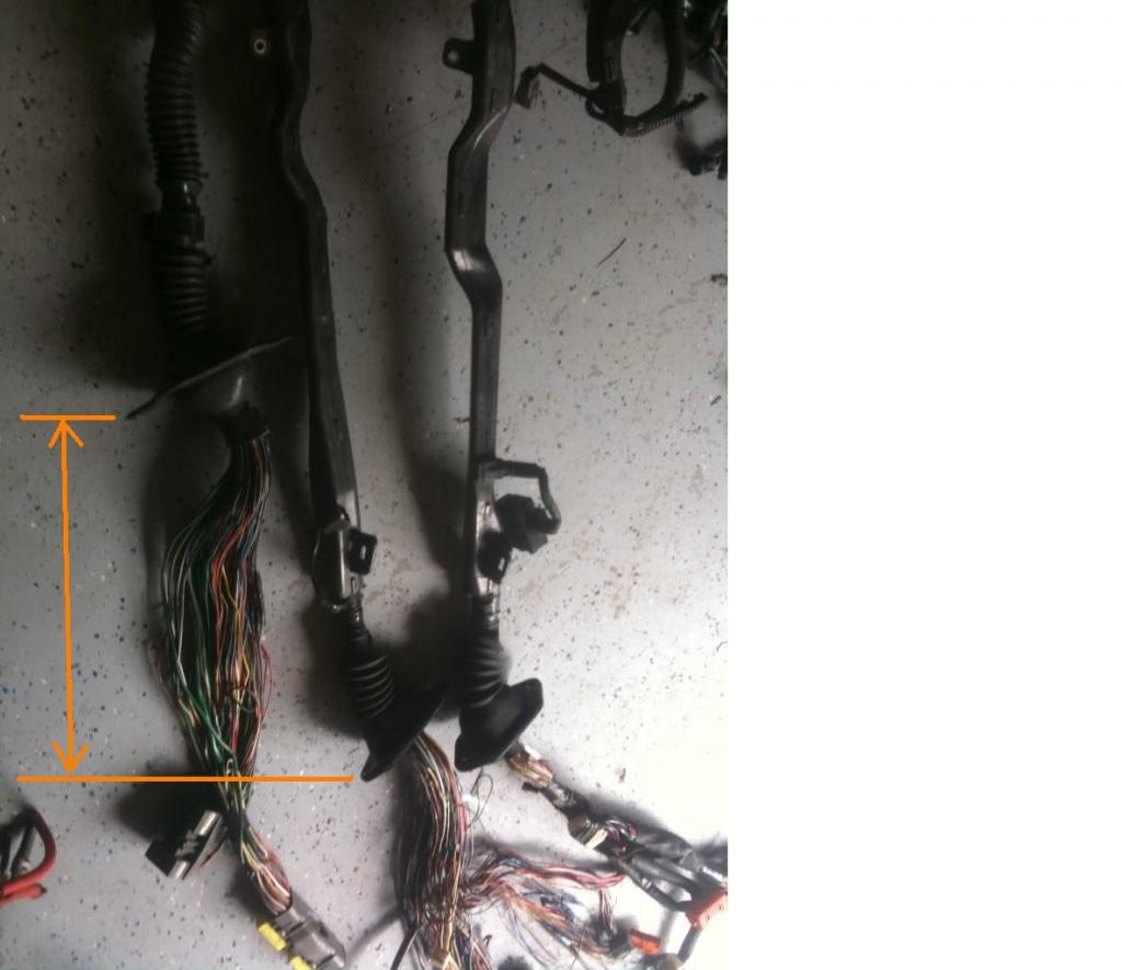
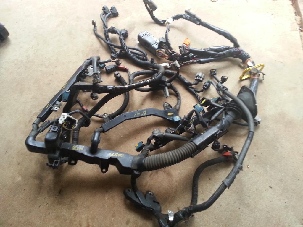
Let me give you pictures of different harnesses so you have an idea on how they look like. The Aristo (2jzgte) on top , then SC300 (2jzge) , then Supra MKIV (2jzge) .
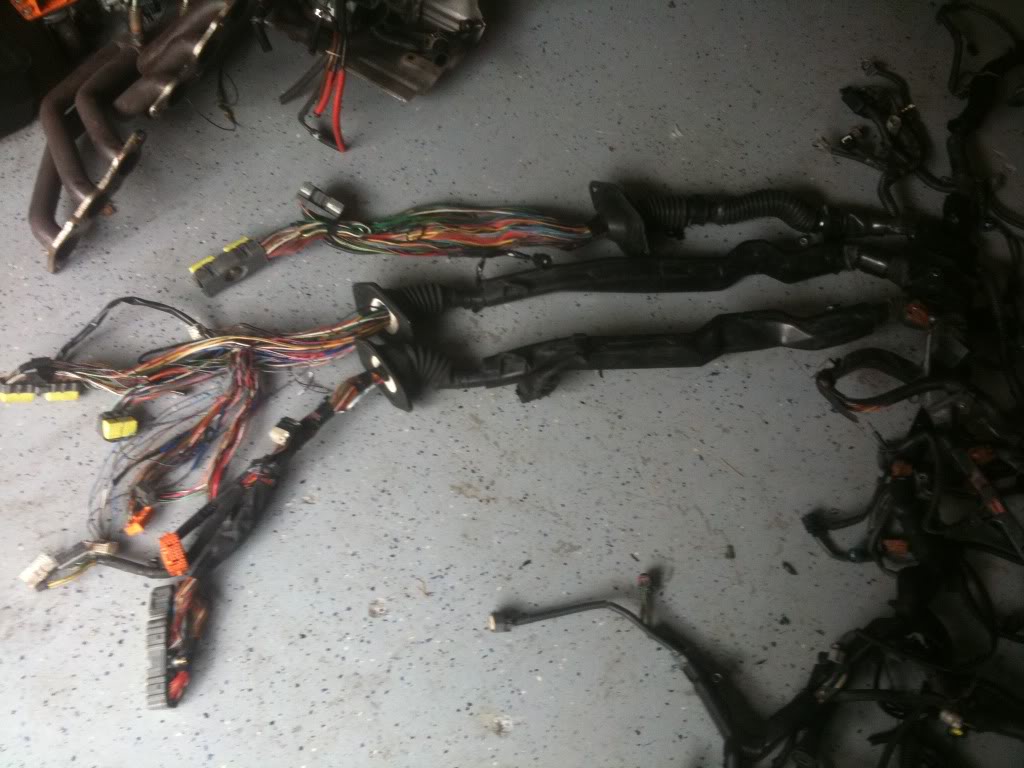
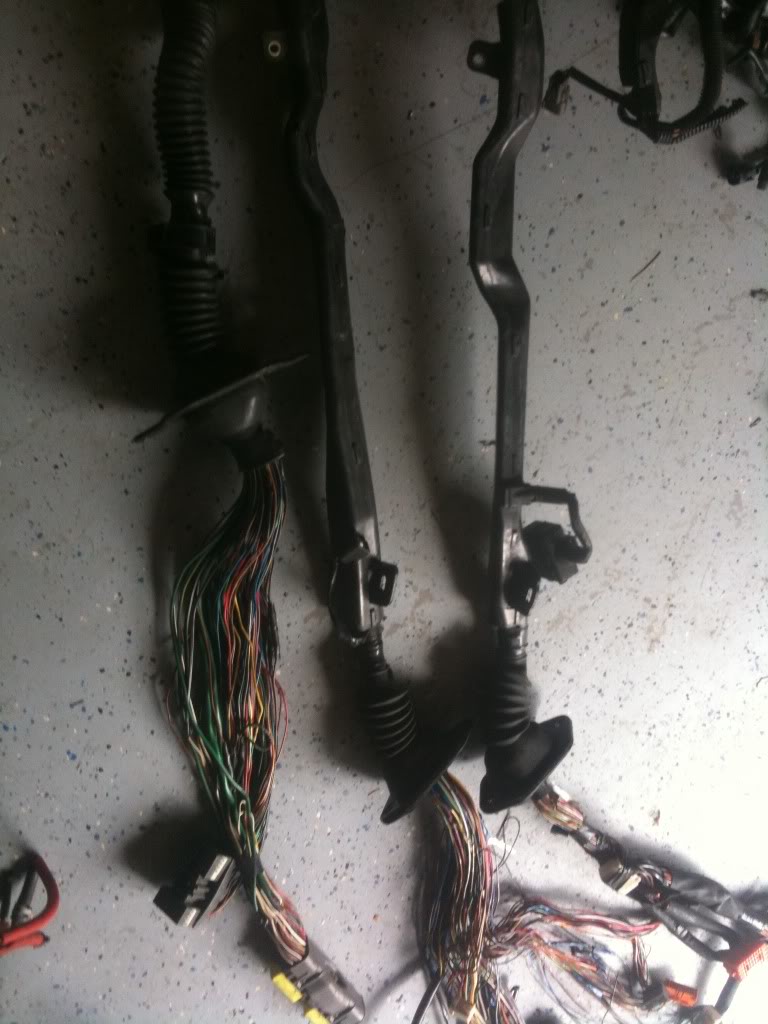
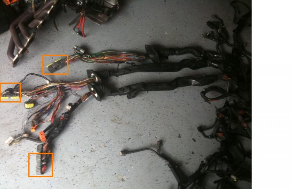
Observe them , they have something in common , the 80 pin connector which I enclosed with an orange rectangle . The rest of the plugs vary depending on the particular car .
Can you now tell why the Aristo 2jzgte harness needs extending ? Japanese cars are right hand driven so their harnesses goes through the left side of the firewall. To use such harnesses on our USDM cars , you need to extend them. How much extending you might ask . It all depends on your harness ? Not all SC300 harnesses have exactly the same length . They need to be extended by around 16" to 22" . I usually go for around 18". I even got away with extending one only by 12" .
When I did my 2jzgte harness for my SC400 ( Red Mamba 1 ) almost two years ago , I wanted to document every step but saw a lot of threads already discussing it. So I decided against it. In-spite of those threads , I still got a lot of PMs from members here asking me questions about it. In fact , two of my friends here started working on their harnesses but eventually got scared and gave up , I ended up working on their harnesses . You guys know who you are and owe me big time
. You know I love drinking Margarita ... hint hint hint ... lmaol . With the insistence of some friends and our moderator Mark (1jzpwrd) I have decided to do this write up titled " 2jzgte Wiring Harness Made Easy ". The original write-up is on my build thread https://www.clublexus.com/forums/bui...mkivs-132.html .This 2jzgte harness build is my own way of doing it. It may not be the best way to do it but I was successful on my first try in doing one for my Red Mamba 1 with a built auto transmission and all the other harnesses I have worked on for my friends. As a DISCLAIMER , I am not taking any responsibility for anyone using this as a reference. Though I have proof read what I wrote , there may still be typographical errors on this write-up. I suggest you learn the process of how I did it , how I counter checked the pin numbers and where wires go or should go by analyzing the wiring diagrams thus you probably will be able to spot errors if ever there are on this write up. Doing is a lot easier than writing what you have done and I for one am not a writer .
If you guys decide to work on your own 2jzgte harness , I do hope you are successful and thereby help you save lots of money. We all know it is not cheap to get a harness done. You are looking at the vicinity of $750 - $1200 depending if it is manual , auto or there are added plugs and wiring plus the cost to replace your broken plugs.
With this harness build thread , we have two Non VVTi Aristo 2jzgte engine harnesses that came with the Aristo 2jzgte swaps that we normally buy from the JDM dealers. These usually have the auto transmissions. I also have two 1992 SC300 engine harnesses with auto transmissions. Out of these harnesses , we should be able to make a harness for a 1992 SC300 2jzgte with manual transmission and another one for a 1992 SC300 2jzgte with auto transmission. I won't be able to make one for the SC400 since I am done with my 2jzgte SC400 while my two 6 speed MKIVs were built by BoostLogic and Majestic Motor Sports. But I will include the pertinent informations and diagrams for the SC400 and MKIV NA so if you have one of these cars , you can still follow the harness build thread and make a harness for it.
The harness build will have the following parts
Part I Cleaning Up the Aristo 2jzgte Harness
Part II Extracting the 40 pin ECU and Body Plugs from the SC300 engine harness
Part III Merging the Aristo 2jzgte harness with the 40 pin ECU and Body Plugs
Part IV Others
Part V Connectors Part Numbers
Part VI Questions & Answers
Part I : Cleaning up the Aristo 2jzgte Harness
Let me give you pictures of different harnesses so you have an idea on how they look like. The Aristo (2jzgte) on top , then SC300 (2jzge) , then Supra MKIV (2jzge) .


Observe them , they have something in common , the 80 pin connector which I enclosed with an orange rectangle . The rest of the plugs vary depending on the particular car .

Can you now tell why the Aristo 2jzgte harness needs extending ? Japanese cars are right hand driven so their harnesses goes through the left side of the firewall. To use such harnesses on our USDM cars , you need to extend them. How much extending you might ask . It all depends on your harness ? Not all SC300 harnesses have exactly the same length . They need to be extended by around 16" to 22" . I usually go for around 18". I even got away with extending one only by 12" .

Last edited by gerrb; 12-15-15 at 07:26 PM.
 01-31-14, 01:05 PM
#2
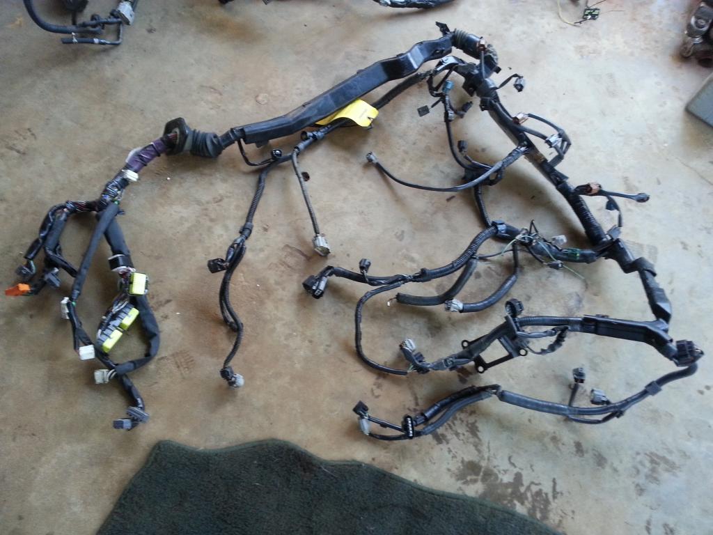
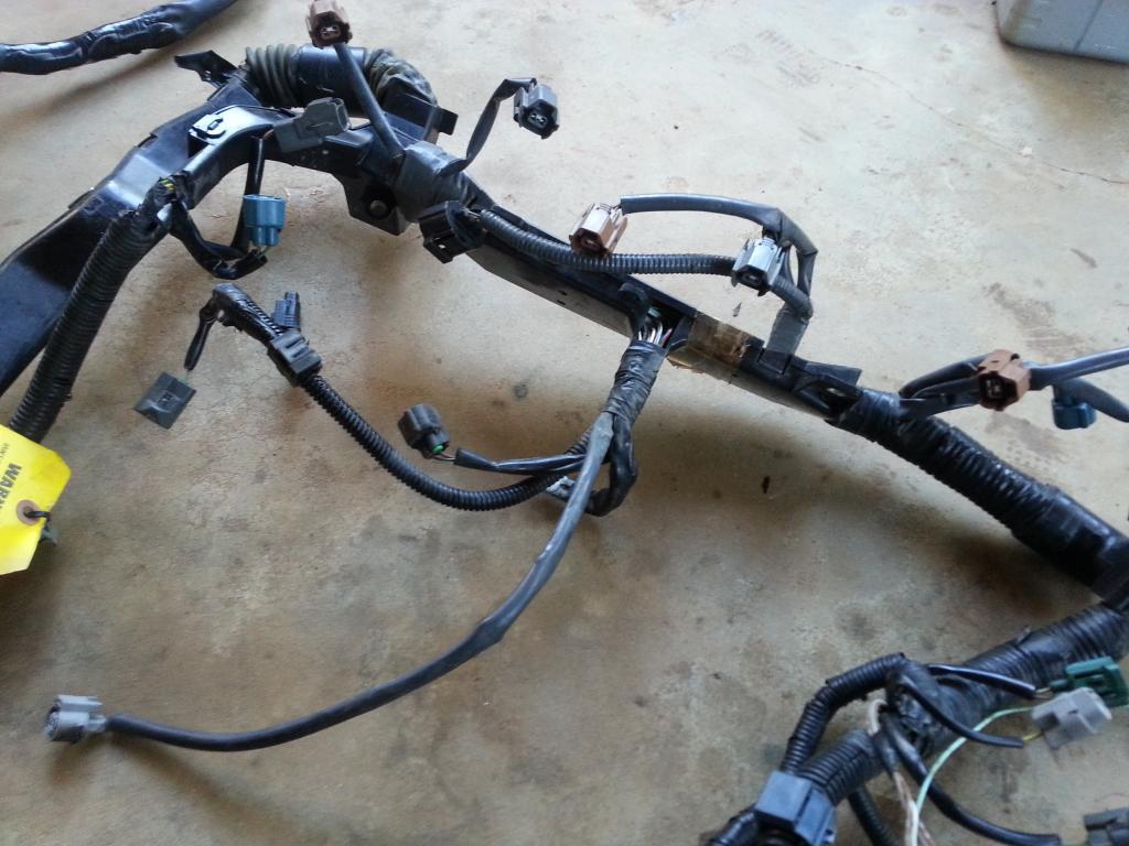
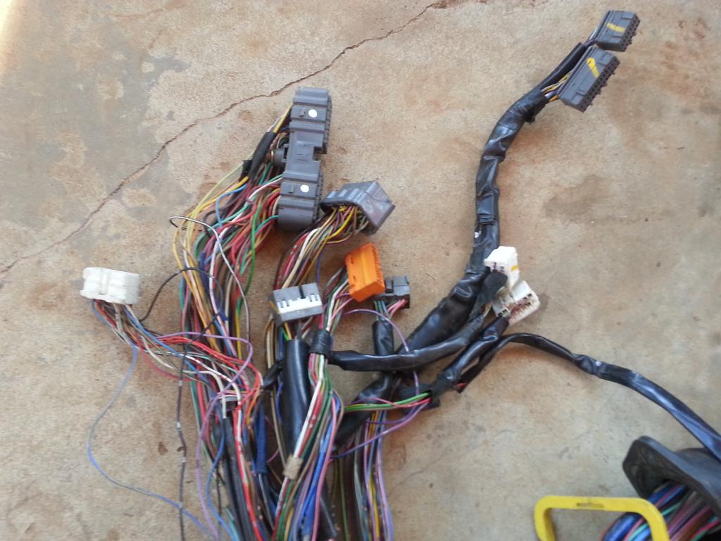
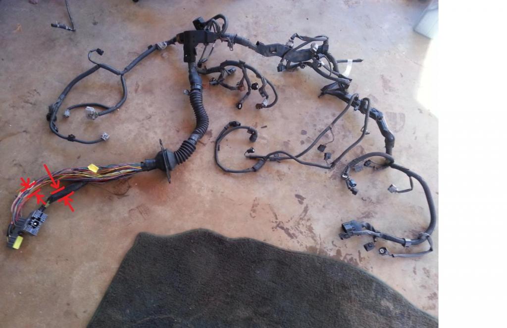
Here is a detailed picture of an Aristo 2jzgte harness that comes with the engine swap you will get.
Whole uncut harness
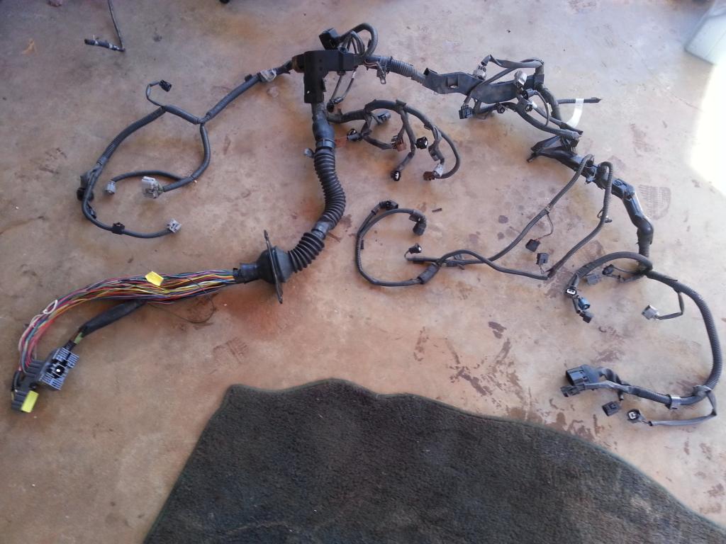
The following pictures are close-up pictures of the uncut harness
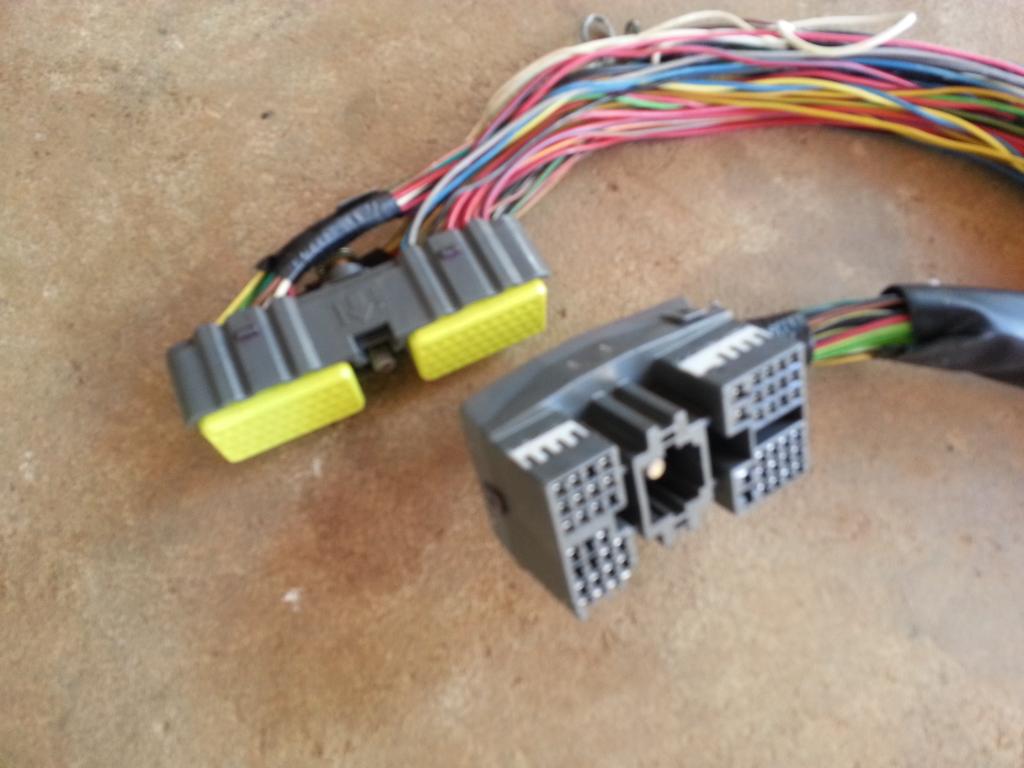
80 pin harness with the Big Gray Body Plug
They normally come with auto transmissions so they have the plugs / wiring to control the transmission.
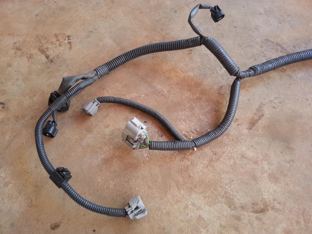
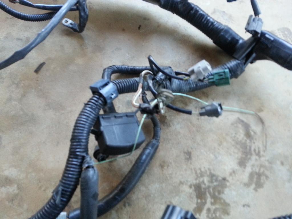
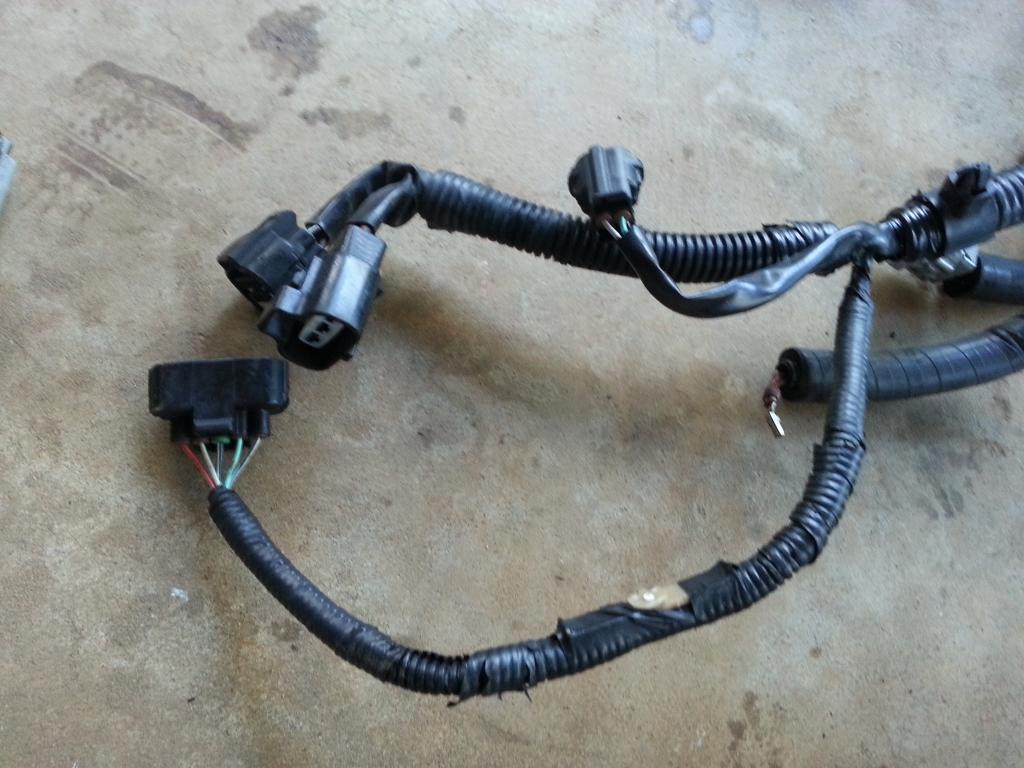
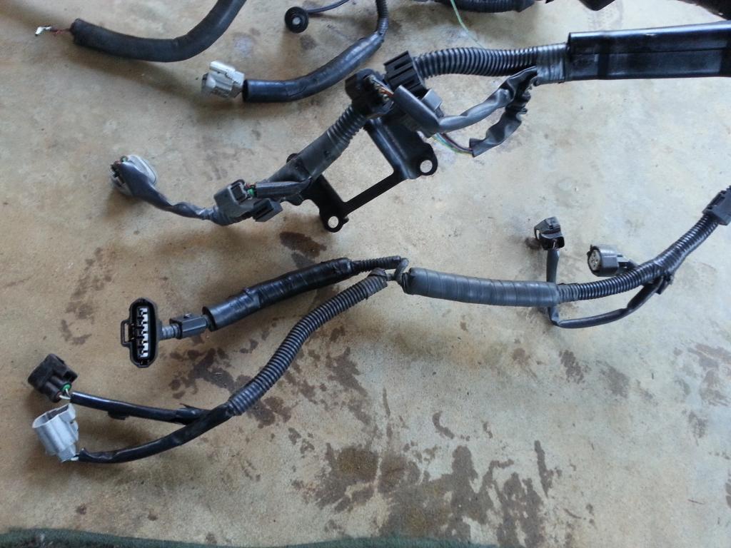
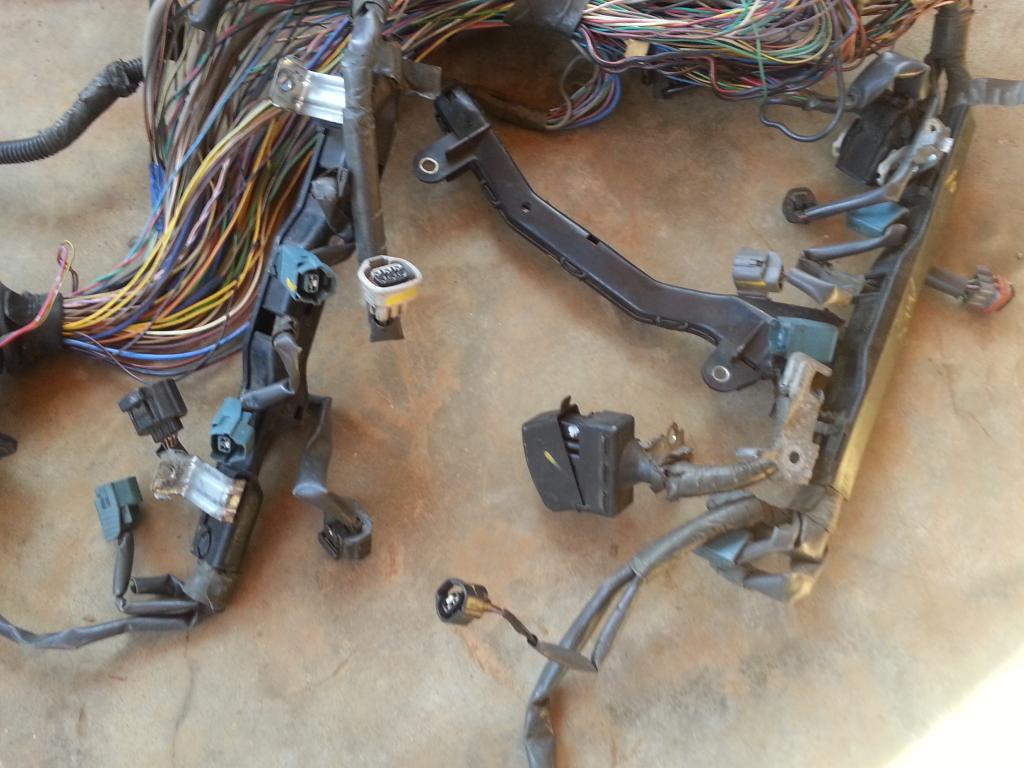
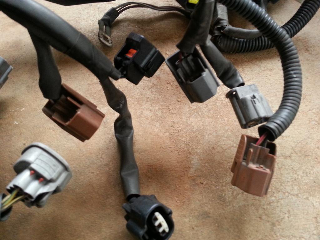
Injectors , Cam sensors , IACV , Map and Air Temp sensors connectors
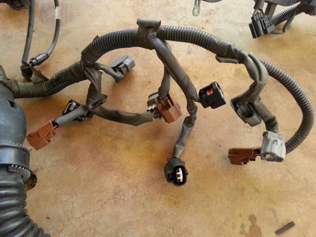
#1 injector , TPS , sub-tps , oil pressure sensor , knock sensor , throttle motor valve , Ground Front Side of Intake Manifold connectors
Coils, VSVs connectors
Igniter , noise filter , crank , coolant temp , coolant gauge sender and VSV connectors
Diagnostic port , knock , starter , ground connectors
Whole uncut harness

The following pictures are close-up pictures of the uncut harness
80 pin harness with the Big Gray Body Plug

They normally come with auto transmissions so they have the plugs / wiring to control the transmission.

Injectors , Cam sensors , IACV , Map and Air Temp sensors connectors

#1 injector , TPS , sub-tps , oil pressure sensor , knock sensor , throttle motor valve , Ground Front Side of Intake Manifold connectors

Coils, VSVs connectors

Igniter , noise filter , crank , coolant temp , coolant gauge sender and VSV connectors

Diagnostic port , knock , starter , ground connectors

Last edited by gerrb; 01-31-14 at 01:12 PM.
01-31-14, 01:12 PM
#3
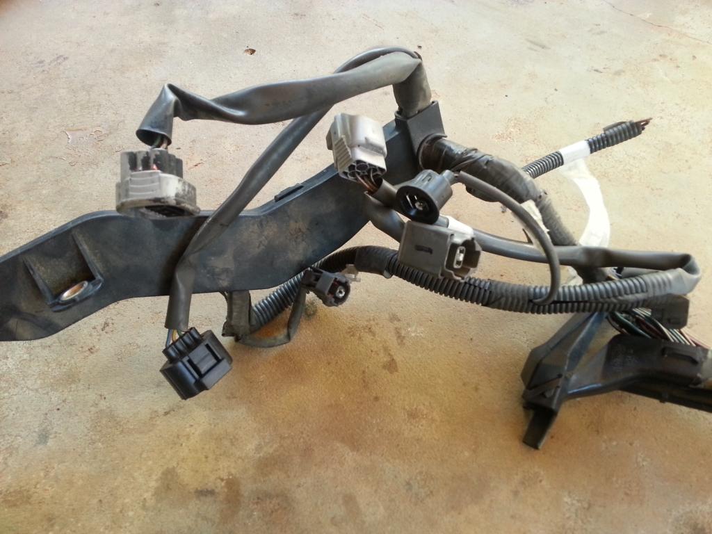
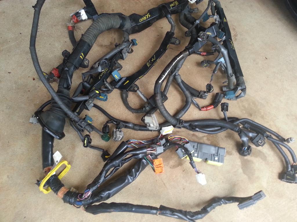
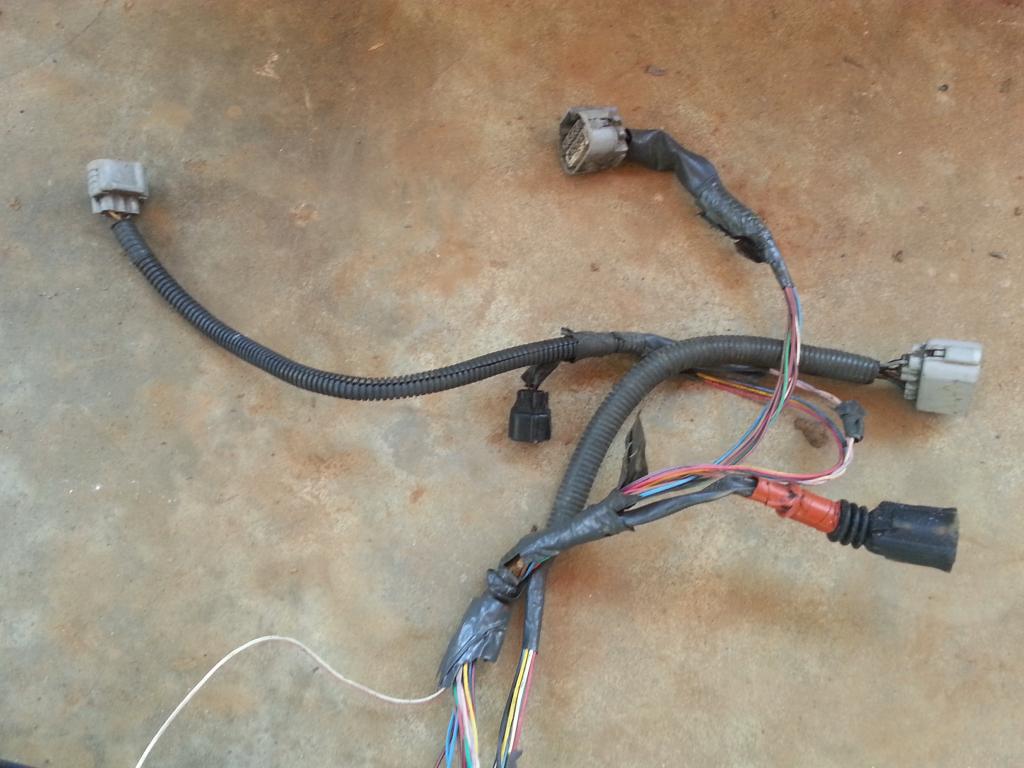
This is a picture of your SC300 harness.
80 pin connector , 40 pin connector and the body plugs
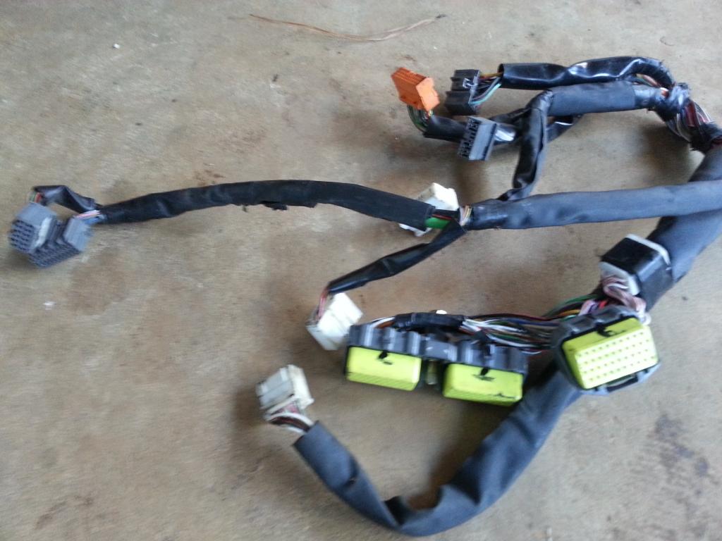
This harness had the auto transmission connectors .
Here you see the injectors , knock sensor connectors
You got the diagnostic port , ground , knock sensor connectors
Those two big connectors you find front lower part of your fusebox.
Coil, filter , igniter , tps , coolant connectors

80 pin connector , 40 pin connector and the body plugs

This harness had the auto transmission connectors .

Here you see the injectors , knock sensor connectors

You got the diagnostic port , ground , knock sensor connectors

Those two big connectors you find front lower part of your fusebox.

Coil, filter , igniter , tps , coolant connectors

Last edited by gerrb; 01-31-14 at 01:15 PM.
01-31-14, 01:15 PM
#4
I don't have new pictures of an SC400 harness. These I took for someone here some time back. This harness is from a 1992 SC400 with auto transmission. BTW , no USDM SC400 came out with manual transmission from the factory.
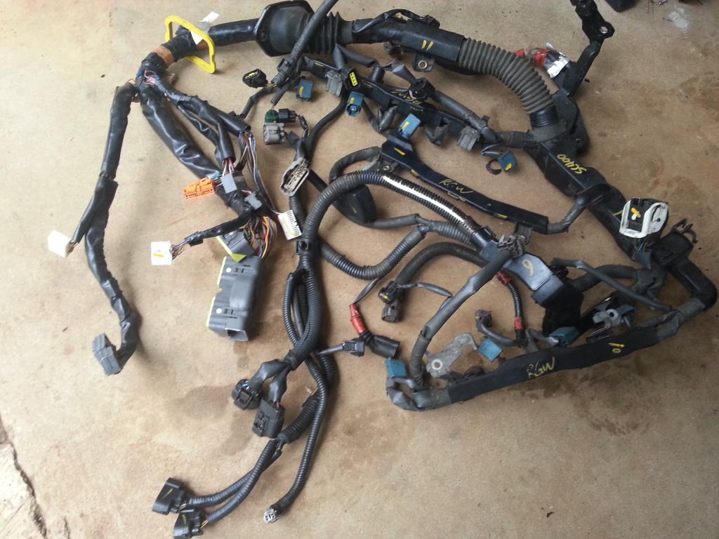
Observe the 80 pin, 40 pin and most of the body plugs . Don't they look similar with that of the SC300 ?
So what are these 80 pin and 40 pin connectors for ? They are actually the connectors to the ECU. They link your engine components , sensors to your Engine ECU whether it is a 2jzge , 1uzfe or your new 2jzgte.
What are the body plugs for ? The body plugs connect the engine components , sensors or ECU to your dashboard cluster or other components of your car .
IF you look back , the Aristo , SC300 , SC400 harness have all one thing in common , the 80 pin connector . Take note though that not all of them have same pin configuration. What does that mean ? Not all pins are used in the same manner by all of those three harnesses. Let's say pin 6 may be used differently by the other. They also have different body plugs though the SC300 and SC400 have similar ones but again may have different pin configurations.
SC400 injectors , diagnostic port , IACV , etc
Big plugs you see on the SC400 lower front fuse box

Auto transmission connectors
O2 sensor connector
I will leave the Supra MKIV wiring harness out of the picture now . I just want to let people know that not because you bought a MKIV TT 2jzgte harness (whether for auto or manual) , it will work with our SC300 or SC400 2jzgte swaps. They have different body plugs . They would not work without any modifications on them meaning you have to remove the plugs distinct to the MKIV and incorporate some plugs (like body plugs) that are distinct to our SC300 / SC400 cars.


Observe the 80 pin, 40 pin and most of the body plugs . Don't they look similar with that of the SC300 ?
So what are these 80 pin and 40 pin connectors for ? They are actually the connectors to the ECU. They link your engine components , sensors to your Engine ECU whether it is a 2jzge , 1uzfe or your new 2jzgte.
What are the body plugs for ? The body plugs connect the engine components , sensors or ECU to your dashboard cluster or other components of your car .
IF you look back , the Aristo , SC300 , SC400 harness have all one thing in common , the 80 pin connector . Take note though that not all of them have same pin configuration. What does that mean ? Not all pins are used in the same manner by all of those three harnesses. Let's say pin 6 may be used differently by the other. They also have different body plugs though the SC300 and SC400 have similar ones but again may have different pin configurations.

SC400 injectors , diagnostic port , IACV , etc

Big plugs you see on the SC400 lower front fuse box

Auto transmission connectors

O2 sensor connector

I will leave the Supra MKIV wiring harness out of the picture now . I just want to let people know that not because you bought a MKIV TT 2jzgte harness (whether for auto or manual) , it will work with our SC300 or SC400 2jzgte swaps. They have different body plugs . They would not work without any modifications on them meaning you have to remove the plugs distinct to the MKIV and incorporate some plugs (like body plugs) that are distinct to our SC300 / SC400 cars.
Last edited by gerrb; 01-31-14 at 01:18 PM.
01-31-14, 01:18 PM
#5
Let me go back on the Aristo 2jzgte harness which you got with your 2jzgte swap . I will always start with this harness as my base . Why ? Most of the major plugs / wiring needed to run your engine is already there , done for you. They are already installed in the right places.
Before unwrapping your harness , take note of the diameter or size of the wrapped wires. WHY ? The firewall hole on the passenger side is not that big. Whatever you do on that harness make sure that you will still be able to insert it into that hole going to the passenger footwell. This will be more important when you lengthen those wires and do soldering and shrink wrapping. The wrapped harness becomes bigger.
Remember it is a 2jzgte harness already though for an aristo car and not SC300 / SC400. So truly all you need to do is replace that big gray aristo body plug with all the body plugs and 40 pin connector of the SC300 / SC400 .
Try to recall for a moment what I previously said about the body plugs and 40 pin connector . The 40 pin connector will house some of the pins needed to get your car running . Like many of the auto transmission wiring go to that connector and the body plugs are used to connect your engine components and ecu to the components in your car like cluster , switches , gauges , etc.
BEFORE WE GO AHEAD , let me warn you , CLEANLINESS or ORDERLINESS is very important. Do things in small phases. IF you are not sure you won't be confused , don't try to unwrap all covers or tapes of your harness. I have seen some who have unwrapped everything at once and all wires got messed up and gave up due to the confusion and the harness becoming a ball of messed wires.
Let me assume some things here .
A) You have and know how to use the multi-tester or ohmmeter or connectivity probe / analyzer to check connections between two or more points.
B) You have the simple tools needed like soldering iron or gun , screw drivers , wire cutter / splicer , etc.
C) You have the supplies necessary that goes with your tools like soldering paste , soldering wire , heat shrink , etc.
Let me introduce here what I call "THE DRILL" .
A) Decide if you need the plug and wires depending on your particular setup .
..A1) IF YES ( that means you are keeping the plug ) , then
......A1a) Inspect the connector (plug) if it is physically damaged
......A1b) Replace that plug if its casing or lock is broken
......A1c) Go through all the wires of that plug
.........A1c1) Trace the wire by finding the pin from the plug where it goes to
............A1c11) If the wire ends at the 80 pin ECU connector OR Other Plug (except Big Gray Aristo Plug) then leave it where it is. That is where it should be anyway.
............A1c12) If the wire ends at the Big Gray Aristo Plug then pull it out from there and label it..
.........A1c2) If the wire ends at the 80 pin ECU connector OR Big Gray Aristo Plug then EXTEND IT otherwise you are not extending the wire.
.........A1c3) If the wire had been extended then Heat Shrink Wrap those solder points ( make sure no strand of wire is out of that heat shrink )
.........A1c4) Check connectivity between the two end points for that particular wire which you have just extended.
......A1d) Cover the wires of the plug with electrical tape and corrugated flexible hose once you are done with every single wire on that plug.
...A2) IF NO ( that means you are NOT keeping the plug ) and YOU ARE NOT KEEPING THE WIRES for future needs then start pulling the plug and its wires out
...A3) IF NO ( that means you are NOT keeping the plug ) BUT YOU ARE KEEPING THOSE WIRES for other components
......A3a) Remove the stock connector
......A3b) Extend the wires you are keeping and pull out the wires you do not need.
......A3c) Heat Shrink Wrap those solder points ( make sure no strand of wire is out of that heat shrink )
......A3d) Check connectivity between the two end points for that particular wire which you have just extended.
......A3e) Label the wire on both ends so you know it is an extra wire and which end point goes to the other end point
B) Update your CHART .
You have to know that drill really well by heart .You will do it many times on this 2jzgte harness build.
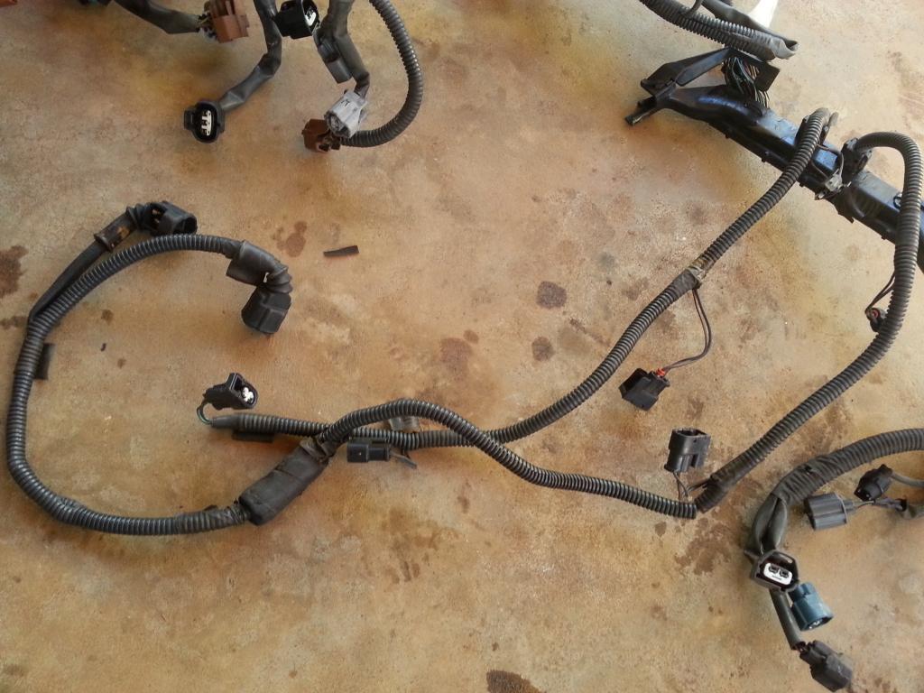
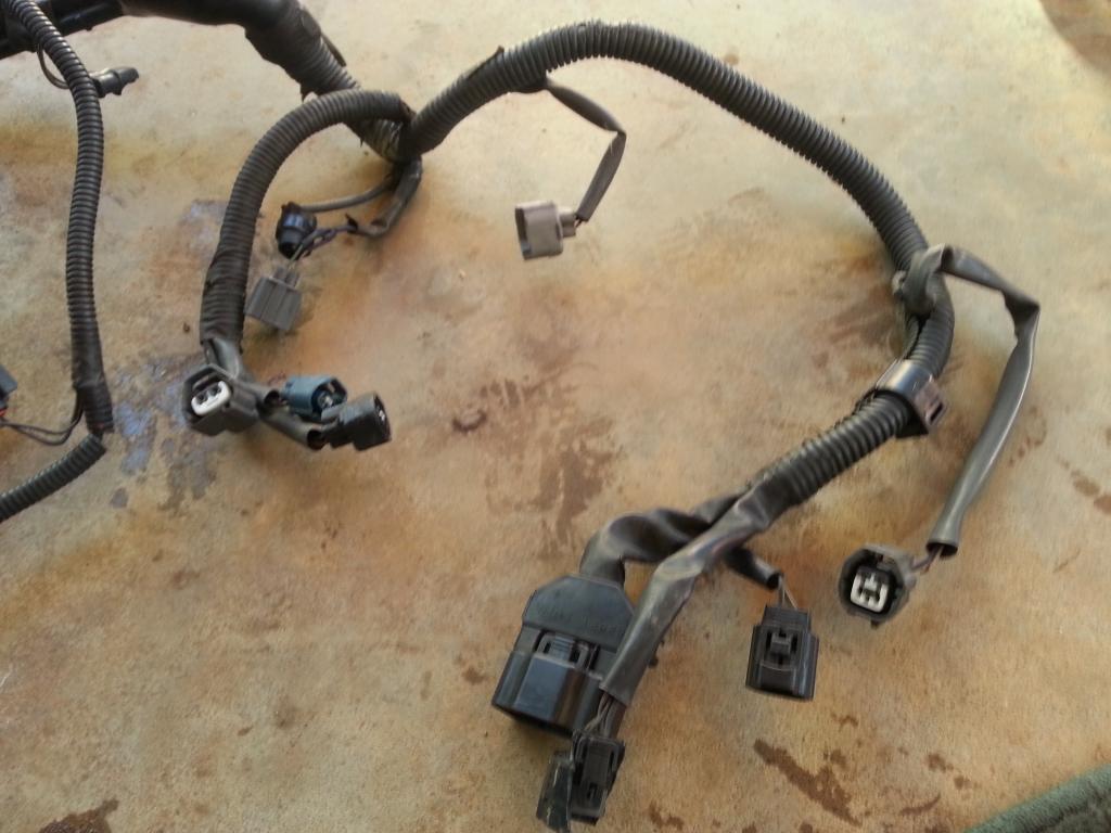
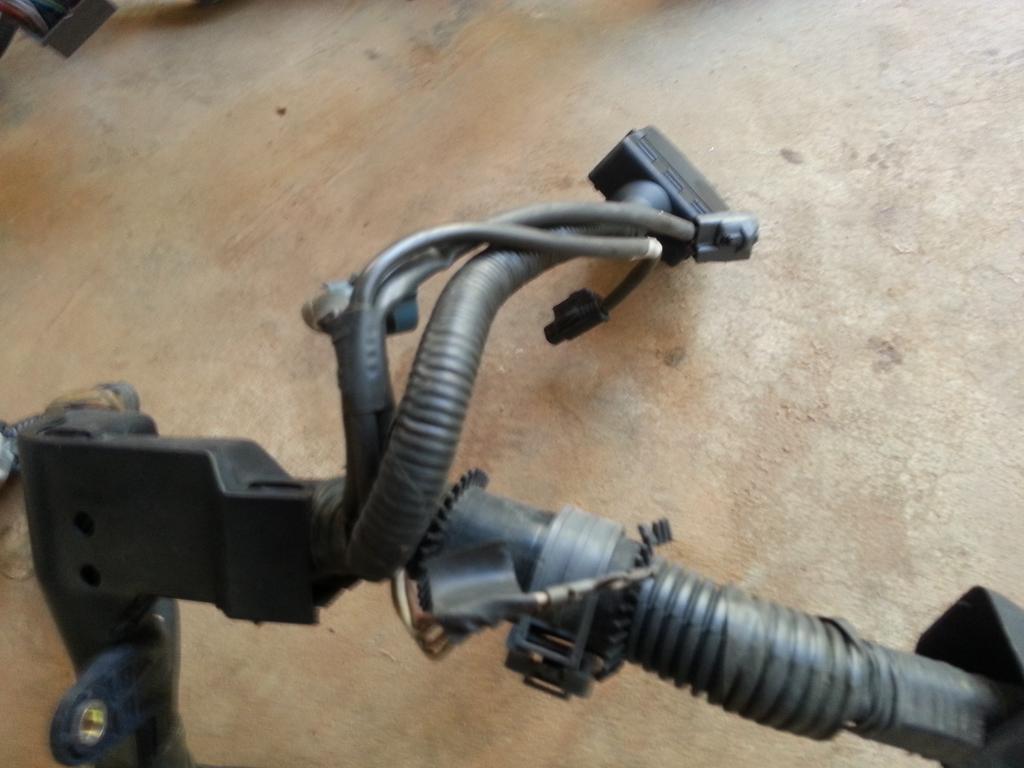
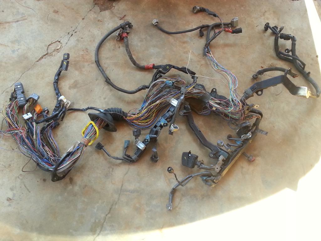
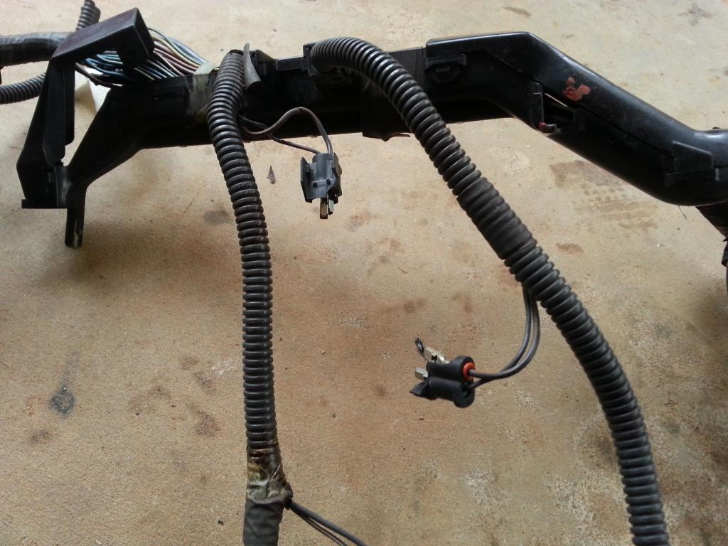
You need to inspect well your 2jzgte harness . How many plugs are broken or missing ? Most of them get brittle especially their locks. Make a list of what connectors you need to replace. You might need to buy some of them or get them from an extra harness you have. If you can get all those broken plugs and the wires you need for extending before you start the actual work then you can work continuously on the harness.
Here you see broken coil connectors.
Injectors and cam connectors with broken locks
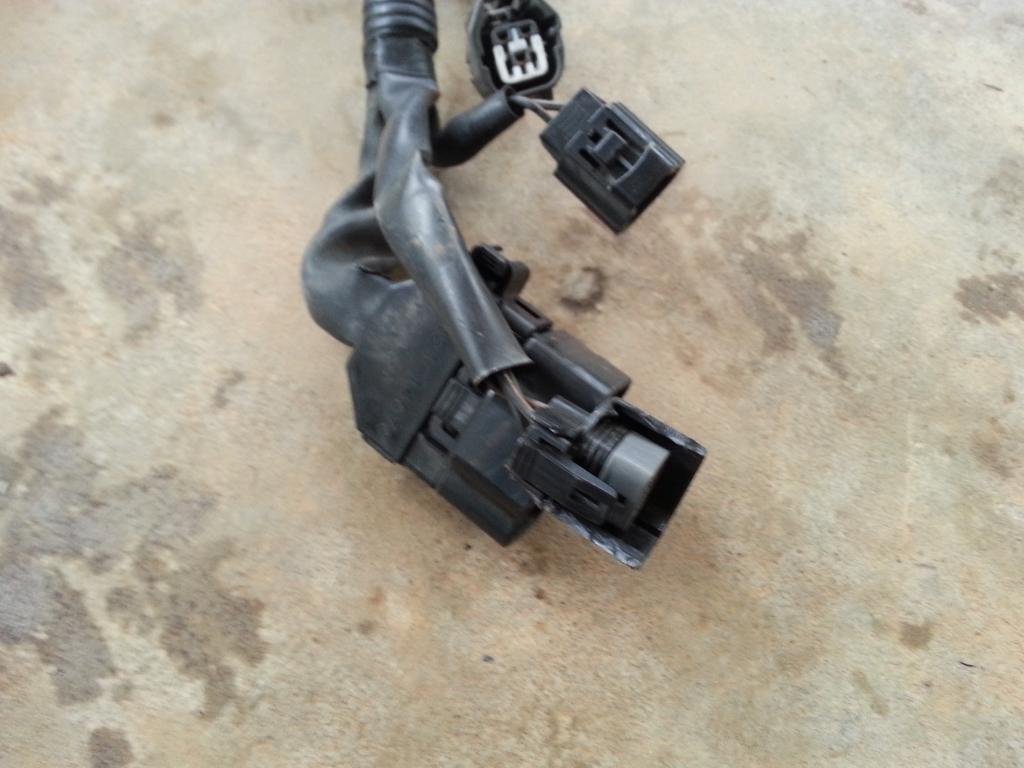
Another connector with a broken housing
You got to identify all the wires that are broken or are not insulated . You don't want exposed wires and get shorts that can damage components or start a fire.
Broken / Cut wires
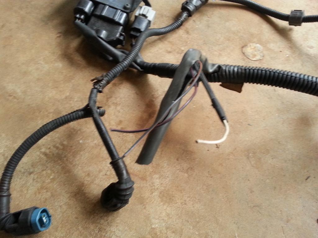
Once you have figured out what connectors need to be replaced and wires that are exposed , it is time to secure the parts you need so you can get the ball rolling.
With regards thickness of wires. ALWAYS use the same gauge (size) of wire or bigger. The amount of current (amperes) that goes through those wires have already been computed by Toyota. All you need is use at least same size of wire so you don't burn anything or start any engine bay fire with too much current going through the wires which causes the wires to heat up and eventually burn.
Also consider if you are using other set of injectors or aftermarket connectors for MAP , Air Intake Temp , Fuel & Oil Pressure , Coolant & Oil Temp and others. You need to get their pigtails or connectors so you can incorporate them into your harness.
Depending on your setup , like if you are going single turbo , some of the connectors on this harness like VSVs can be removed / deleted OR those wires can be used for other stuff you would include in your setup like AIT Sensor , Boost Solenoid . Just take note of the wiring sizes and use them accordingly meaning small wires can only carry small current so you can't use those wires for components that consume a lot of current. Remember what I just said regarding thickness of wires.
Before unwrapping your harness , take note of the diameter or size of the wrapped wires. WHY ? The firewall hole on the passenger side is not that big. Whatever you do on that harness make sure that you will still be able to insert it into that hole going to the passenger footwell. This will be more important when you lengthen those wires and do soldering and shrink wrapping. The wrapped harness becomes bigger.

Remember it is a 2jzgte harness already though for an aristo car and not SC300 / SC400. So truly all you need to do is replace that big gray aristo body plug with all the body plugs and 40 pin connector of the SC300 / SC400 .
Try to recall for a moment what I previously said about the body plugs and 40 pin connector . The 40 pin connector will house some of the pins needed to get your car running . Like many of the auto transmission wiring go to that connector and the body plugs are used to connect your engine components and ecu to the components in your car like cluster , switches , gauges , etc.
BEFORE WE GO AHEAD , let me warn you , CLEANLINESS or ORDERLINESS is very important. Do things in small phases. IF you are not sure you won't be confused , don't try to unwrap all covers or tapes of your harness. I have seen some who have unwrapped everything at once and all wires got messed up and gave up due to the confusion and the harness becoming a ball of messed wires.
Let me assume some things here .
A) You have and know how to use the multi-tester or ohmmeter or connectivity probe / analyzer to check connections between two or more points.
B) You have the simple tools needed like soldering iron or gun , screw drivers , wire cutter / splicer , etc.
C) You have the supplies necessary that goes with your tools like soldering paste , soldering wire , heat shrink , etc.
Let me introduce here what I call "THE DRILL" .
A) Decide if you need the plug and wires depending on your particular setup .
..A1) IF YES ( that means you are keeping the plug ) , then
......A1a) Inspect the connector (plug) if it is physically damaged
......A1b) Replace that plug if its casing or lock is broken
......A1c) Go through all the wires of that plug
.........A1c1) Trace the wire by finding the pin from the plug where it goes to
............A1c11) If the wire ends at the 80 pin ECU connector OR Other Plug (except Big Gray Aristo Plug) then leave it where it is. That is where it should be anyway.
............A1c12) If the wire ends at the Big Gray Aristo Plug then pull it out from there and label it..
.........A1c2) If the wire ends at the 80 pin ECU connector OR Big Gray Aristo Plug then EXTEND IT otherwise you are not extending the wire.
.........A1c3) If the wire had been extended then Heat Shrink Wrap those solder points ( make sure no strand of wire is out of that heat shrink )
.........A1c4) Check connectivity between the two end points for that particular wire which you have just extended.
......A1d) Cover the wires of the plug with electrical tape and corrugated flexible hose once you are done with every single wire on that plug.
...A2) IF NO ( that means you are NOT keeping the plug ) and YOU ARE NOT KEEPING THE WIRES for future needs then start pulling the plug and its wires out
...A3) IF NO ( that means you are NOT keeping the plug ) BUT YOU ARE KEEPING THOSE WIRES for other components
......A3a) Remove the stock connector
......A3b) Extend the wires you are keeping and pull out the wires you do not need.
......A3c) Heat Shrink Wrap those solder points ( make sure no strand of wire is out of that heat shrink )
......A3d) Check connectivity between the two end points for that particular wire which you have just extended.
......A3e) Label the wire on both ends so you know it is an extra wire and which end point goes to the other end point
B) Update your CHART .
You have to know that drill really well by heart .You will do it many times on this 2jzgte harness build.
You need to inspect well your 2jzgte harness . How many plugs are broken or missing ? Most of them get brittle especially their locks. Make a list of what connectors you need to replace. You might need to buy some of them or get them from an extra harness you have. If you can get all those broken plugs and the wires you need for extending before you start the actual work then you can work continuously on the harness.
Here you see broken coil connectors.

Injectors and cam connectors with broken locks

Another connector with a broken housing

You got to identify all the wires that are broken or are not insulated . You don't want exposed wires and get shorts that can damage components or start a fire.
Broken / Cut wires

Once you have figured out what connectors need to be replaced and wires that are exposed , it is time to secure the parts you need so you can get the ball rolling.
With regards thickness of wires. ALWAYS use the same gauge (size) of wire or bigger. The amount of current (amperes) that goes through those wires have already been computed by Toyota. All you need is use at least same size of wire so you don't burn anything or start any engine bay fire with too much current going through the wires which causes the wires to heat up and eventually burn.
Also consider if you are using other set of injectors or aftermarket connectors for MAP , Air Intake Temp , Fuel & Oil Pressure , Coolant & Oil Temp and others. You need to get their pigtails or connectors so you can incorporate them into your harness.
Depending on your setup , like if you are going single turbo , some of the connectors on this harness like VSVs can be removed / deleted OR those wires can be used for other stuff you would include in your setup like AIT Sensor , Boost Solenoid . Just take note of the wiring sizes and use them accordingly meaning small wires can only carry small current so you can't use those wires for components that consume a lot of current. Remember what I just said regarding thickness of wires.
01-31-14, 01:22 PM
#6
I am not sure if it is allowed here to post a link but the following info I extracted from this site ( http://wilbo666.pbworks.com/w/page/3...ngine%20Wiring)
BIG THANKS to the owners of that site for the info and if the link will be deleted because it is not allowed ,just do a google search "WILBO666 2jzgte" .
I am posting the info here so all info that may help you understand your 2jzgte harness better will all be in one place.
REFERENCE INFO for JDM 2jzgte Engine - ECU PINOUT
80 pin connector on the left and 40 pin connector on the right.

40 Pins Plug - Configuration ( Pin Number , Symbol , Definition , Input or Output , Description )
Pin 1 - IGSW , Ignition Switch , Input , This pin is used to determine if the ignition is ON. The engine ECU is turned on by this signal. This pin is connected to battery voltage when the ignition switch is in RUN and CRANK positions.
Pin 2 - SP1 , No.1 Speed Sensor , Input , This pin is used to determine vehicle speed.Vehicle speed is used in idle control, automatic transmission shift control, speed limiting etc. Two speed sensors are used to provide a backup. This pin is connected to the combination meter speed output which outputs 4 pulses (Open collector square wave pulses) per No.1 speed sensor shaft revolution. The combination meter receives its speed signal from the No.1 speed sensor which is located on the right, rear side of automatic transmission and outputs 4 pulses (0 to Battery Voltage square wave pulses) per sensor shaft revolution.
Pin 3 - KD , Kick Down Switch , Input , This pin is used to detect when the accelerator pedal is fully depressed. Used to 'kick down' or change down a gear of automatic transmission under full throttle. This pin is Grounded by a switch that is located under the accelerator pedal that is pressed at full throttle. The Kick Down switch is open circuit when the switch is not pressed (Accelerator pedal is not fully depressed). Note: 1991-10 to 1993-08 models only, later models do not have this pin wired or a Kick Down switch installed.
Pin 4 - STP , Stop Light Switch , Input , This pin is used to detect when the brake pedal is depressed. Used to disable the automatic transmission lock up torque converter and exit deceleration fuel cut mode etc. This pin is connected to battery voltage when brake pedal is depressed, the ECU pin is open circuit when the brake pedal is not depressed.
Pin 5 - EGW , Exhaust Gas Temperature Warning Light (Catalytic Converter) , Output , This pin is used to turn ON / OFF the exhaust gas warning light. The exhaust gas warning light comes on to inform of an overheated catalytic converter. This pin is Grounded by the ECU as required to turn the exhaust gas warning light ON. Light ON = Error Condition, light OFF = Normal.
Pin 6 - W , Engine Warning Light (Check Engine Light) , Output , This pin is used to turn ON / OFF the check engine light. The check engine light comes on to inform of a detected engine issue. This pin is Grounded by the ECU as required to turn the Check Engine Light ON. The check engine light should be wired with one side of the light connected to battery voltage (Ignition Switched) and one side of the light connected to this ECU pin. Light ON = Error Condition, light OFF = Normal.
Pin 7 - R , Reverse Gear Automatic Transmission Position Indicator , Input , This pin is used to determine if the automatic transmission shifter is in the Reverse position. The engine ECU needs to energize/de-energize the automatic transmission solenoids to select the correct gear. This pin is connected to battery voltage by the automatic shifter position switch when the automatic transmission shifter is in the 'R' position.
Pin 8 - / / / / / /
Pin 9 - 2 , 2nd Gear Automatic Transmission Position Indicator , Input , This pin is used to determine if the automatic transmission shifter is in the 2nd position. The engine ECU needs to energize/de-energize the automatic transmission solenoids to select the correct gear. This pin is connected to battery voltage by the automatic shifter position switch when the automatic transmission shifter is in the '2' position.
Pin 10 - L , Low Gear Automatic Transmission Position Indicator , Input , This pin is used to determine if the automatic transmission shifter is in the L position. The engine ECU needs to energize/de-energize the automatic transmission solenoids to select the correct gear. This pin is connected to battery voltage by the automatic shifter position switch when the automatic transmission shifter is in the 'L' position.
Last edited by gerrb; 01-31-14 at 01:25 PM.
01-31-14, 01:25 PM
#7
Pin 11 - AD , Auto Drive , Input , This pin is used to signal that cruise control is ON to the engine ECU. Currently unsure what exact action the engine ECU takes based on this signal. This pin is Grounded by the Cruise Control ECU when Auto Drive is engaged.
Pin 12 - OD1 , Over Drive Disable 1 , Input , This pin is used by the Cruise Control ECU to request to disable the automatic transmission over drive gear (4th Gear). The cruise control ECU may need to change to 3rd gear from 4th gear (over drive) to maintain the desired set speed. This pin is Grounded by the Cruise Control ECU to disable the automatic transmissions over drive gear.
Pin 13 / / / / / /
Pin 14 / / / / / /
Pin 15 - ELS , Electrical Load Sense , Input , This pin is used to signal that heavy electrical loads are ON (e.g. rear demister). Heavy electrical loads place more load on the alternator and hence the engine, the engine ECU can adjust for these heavy electrical loads if it is aware of them. This pin is connected to battery voltage when a heavy electrical load is ON.
Pin 16 - TRI , Timing Retard 1? , Input , Timing Retard perhaps? , Reduced ignition time will reduce engine power which is used by the Traction Control ECU to attempt to maintain traction. This pin connects to the Traction Control ECU pin MPC. Perhaps this should be labelled TR1 and have a similar function to TR2?
Pin 17 - TT , Test Terminal , Output , This pin is used to output a diagnostic voltage dependent on throttle position, brake pedal position and automatic transmission gear position. Used to help in diagnosing issues with the TPS, brake and automatic transmission. Refer to TT section.
Pin 18 - P , Power / Normal Auto , Input , This pin is used to select Power or Normal shift patterns for the automatic transmission. Used to modify the automatic transmission shift points to make the automatic transmission shifts more performance orientated. This pin is connected to battery voltage when the Power / Normal switch is in the Power position. Pin is open circuit when the Power / Normal switch is in the Normal Position. In power mode gears are held longer and the automatic transmission will not select 1st gear when the automatic shifter is manually placed in the '2' position.
Pin 19 - TE2 , Test mode select 2 , Input , This pin is used to select the test mode during which diagnostic serial data is sent out the VF1 pin. Used to help in diagnosing issues. This pin is connected to Ground to enable test mode.
Pin 20 - TE1 , Test mode select 1 , Input , This pin is used to select the test mode during which diagnostic codes are flashed on the check engine light . Used to help in diagnosing issues. This pin is connected to Ground to enable test mode.
Pin 21 - DI , Diagnostic Indication - Fuel Pump Control , Input , This pin is used to determine if the Fuel Pump ECU is healthy. Lets the engine ECU know if the Fuel Pump ECU is healthy, if the Fuel Pump ECU is not healthy the engine ECU stops the output on the FPC pin. This pin is connected to battery voltage when the Fuel Pump ECU is healthy, the pin is open circuit when Fuel Pump ECU is not healthy.
Pin 22 - FPC , Fuel Pump Control , Output , This pin is used to signal the desired fuel pump speed to the Fuel Pump ECU. The fuel pump speed can be reduced at low load conditions to make the fuel quieter and improve fuel pump longevity. This pin outputs a 0V to 5V Pulse Width Modulated (PWM) signal which is connected to the Fuel Pump ECU to control fuel pump speed.
Pin 23 - ACMG , Air Conditioning (AC) Magnetic Clutch Relay , Output , This pin is used to turn the AC magnetic clutch relay ON. ECU control of the AC enables the AC to be turned off during hard acceleration. This pin is Grounded by the ECU as required to turn the AC magnetic clutch relay ON. One side of the AC magnetic clutch relay coil should be wired to this pin and one side of the AC magnetic clutch relay coil should be connected to battery voltage (Ignition switched) and one side of the relay coil connected to this ECU pin.
Pin 24 , M-REL , EFI Main Relay , Output , This pin is used to turn ON the Main EFI Relay which feeds power to the fuel pump, engine ECU, ISCV, engine VSVs and O2 sensor heater circuits, etc. ECU control of the main power relay allows the ECU to remain powered up after engine shutdown to fully open the ISCV. This pin is connected to battery voltage inside the ECU as required to turn the Main EFI Relay ON when the ignition switch is ON. Note that this pin continues to output voltage for a few second after the ignition has been switched off to allow the ISCV to be fully opened by the ECU for the next engine start. One side of the Main EFI Relay coil should be connected to this pin and one side of the Main EFI Relay coil should be connected to Ground.
Pin 25 / / / / / /
Pin 26 / / / / / /
Pin 27 / / / / / /
Pin 28 - OD2 , Over Drive Disable 2 , Input , This pin is used to disable the automatic transmission over drive gear (4th Gear) by a user switch. Used to enable the driver to disable the automatic transmission over drive gear (4th Gear) for towing, hills, etc. This pin is Grounded by the over drive switch to disable the automatic transmission over drive gear.
Pin 29 - CCO , Catalytic Converter Temperature Sensor , Input , This pin is used to measure the catalytic converter temperature. Used to inform the driver of an overheated catalytic converter. This pin connects to a thermistor that is installed after the catalytic converter to sense the catalytic converter temperature. One side of the thermistor should be wired to this pin and one side of the thermistor should be wired to Ground.
Pin 30 - TRO , Timing Retard 0? , Input Timing Retard perhaps? , Reduced ignition time will reduce engine power which is used by the Traction Control ECU to attempt to maintain traction. This pin connects to the Traction Control ECU pin MPR. Perhaps this should be labelled TR0 and have a similar function to TR2?
Pin 31 - +B , EFI Main Relay Switched Power , Input , This pin is used to supply switched battery power to the ECU. Used to supply power. This pin is connected to battery voltage when the Main EFI Relay is energized to supply power to the ECU. The Main EFI Relay is triggered by the engine ECU pin M-REL pin. This pin is connected inside the ECU to the +B1 pin.
Pin 32 - +B1 , EFI Main Relay Switched Power , Input , This pin is used to supply switched battery power to the ECU. Used to supply power. This pin is connected to battery voltage when the Main EFI Relay is energized to supply power to the ECU. The Main EFI Relay is triggered by the engine ECU M-REL pin. This pin is connected inside the ECU to the +B pin.
Pin 33 - BATT , Battery Power , Input , This pin is used to supply constant battery power to the ECU. Constant battery power allows the engine ECU to retain error codes, fuel trims, etc. This pin is connected to battery voltage at all times.
Pin 34 - A/C , Air Conditioning (AC) Request Signal , Input , This pin is used to request that the AC be turned ON. Having an AC request input and a separate control output allows the engine ECU to turn the AC OFF under some conditions, such as hard acceleration. This pin is connected to battery voltage to request that the AC be turned ON. The AC request signal is usually generated by the climate control ECU, however connecting this pin to battery voltage will not guarantee that the AC is turned ON.
Pin 35 / / / / / /
Pin 36 / / / / / /
Pin 37 - TR2 , Timing Retard 2 , Input , This pin is used as a signal to request that the engine ECU retard engine ignition timing. Reduced ignition time will reduce engine power which is used by the Traction Control ECU to attempt to maintain traction. This pin connects to the Traction Control ECU pin TR2.
Pin 38 - NEO , Slave Engine Speed Sensor , Output , This pin is used to supply a copy of the engine speed (NE) signal to the traction control ECU. Engine speed is a useful parameter for traction control. This pin connects to the Traction Control ECU pin NEO.
Pin 39 - VTO2 , Slave Traction Control Throttle Position Sensor , Output , This pin is used to supply a copy of the analogue traction control throttle position (VTA2) signal to the traction control ECU. The measured position of the traction control throttle is a useful parameter for traction control. This pin connects to the Traction Control ECU pin VSH.
Pin 40 - VTO1 , Slave Throttle Position Sensor , Output , This pin is used to supply a copy of the analogue throttle position signal (VTA1) to the traction control ECU. The measured position of the engine throttle is a useful parameter for traction control. This pin connects to the Traction Control ECU pin VTH.
Last edited by gerrb; 01-31-14 at 04:10 PM.
Trending Topics
01-31-14, 01:28 PM
#8
REFERENCE INFO for JDM 2jzgte Engine - ECU PINOUT
80 pin connector on the left and 40 pin connector on the right.

80 Pins Plug - Configuration ( Pin Number , Symbol , Definition , Input or Output , Description )
Pin 1 NCO - Over Drive Direct Clutch Speed Sensor , Input , This pin is used to detect the speed of the automatic transmission OD input shaft. Detection of the automatic transmission OD input shaft speed can be used to improve shift timing and ensure smooth gear shifts. This pin connects to the OD speed sensor located on the left, front side of the automatic transmission and outputs a number of pulses (reluctor pulses) per revolution of the OD direct clutch drum.
Pin 2 / / / / / /
Pin 3 , SP2- , No. 2 Speed Sensor , Input , This pin is used to determine vehicle speed. Vehicle speed is used in idle control, automatic transmission shift control, speed limiting etc. Two speed sensors are used to provide a backup. This pin connects to the No.2 speed sensor located on the left, rear side of the automatic transmission and outputs 4 pulses (reluctor pulses) per revolution of the automatic transmission output shaft.
Pin 4 , E11 , ECU Ground , Input , Ground Used to supply a Ground path to allow current to flow. This pin connects to Ground or the battery negative.
Pin 5 , G2- , Cam Position Sensor No.2 (Rear) , Input , This pin is used to detect the location of the intake camshaft. The engine ECU needs to know if the engine is on the compression or exhaust stroke for sequential spark and ignition, the camshaft position sensor provides this information. This pin connects to the No.2 camshaft position sensor located to the rear of the intake side of the engine head which outputs 1 pulse (reluctor pulse) per camshaft revolution. A pulse is generated slightly before the TDC on the cylinder 1 compression stroke which is used to determine the engine position for sequential ignition and fuel.
Pin 6 , G1- , Cam Position Sensor No.1 (Front) , Input , This pin is used to detect the location of the intake camshaft. The engine ECU needs to know if the engine is on the compression or exhaust stroke for sequential spark and ignition, the camshaft position sensor provides this information. This pin connects to the No.1 camshaft position sensor located to the front of the intake side of the engine head which outputs 1 pulse (reluctor pulse) per camshaft revolution. A pulse is generated slightly before the TDC on the cylinder 1 exhaust stroke which is used to determine the engine position for sequential ignition and fuel.
Pin 7 , NE- , Crank Position Sensor , Input , This pin is used to detect the speed and location of the engine crankshaft. The engine ECU needs to know the position of the engine so that it can accurately provide fuel and ignition. This pin connects to the engine crankshaft position sensor located to the lower front of the exhaust side of the engine near the alternator which outputs 12 pulses (reluctor pulses) per engine crankshaft revolution.
Pin 8 / / / / / /
Pin 9 , S2 , Automatic Transmission No.2 Shift Solenoid , Output , This pin is used to control the automatic transmission No.2 shift solenoid. The automatic transmission gear selection is controlled by electronic solenoids. This pin outputs battery voltage to turn the No.2 shift solenoid ON as required . The No.2 shift solenoid is ON in gears 2 & 3. The other side of the No.2 shift solenoid is Grounded inside the automatic transmission.
Pin 10 , S1 , Automatic Transmission No.1 Shift Solenoid , Output , This pin is used to control the automatic transmission No.1 shift solenoid. The automatic transmission gear selection is controlled by electronic solenoids. This pin outputs battery voltage to turn the No.1 shift solenoid ON as required. The No.1 shift solenoid is ON in gears 1 & 2. The other side of the No.1 shift solenoid is Grounded inside the automatic transmission.
Pin 11 / / / / / /
Pin 12 , SLT- , Automatic Transmission Line Pressure Control Solenoid , Output , This pin is used to control the automatic transmission line pressure control solenoid. The automatic transmission line pressure is controlled by an electronic solenoid. This pin in association with the SLT+ pin outputs Pulse Width Modulated (PWM) battery voltage to turn the line pressure control solenoid ON.
Pin 13 , SLN- , Automatic Transmission Accumulator Back Pressure Solenoid , Output ,This pin is used to control the automatic transmission accumulator back pressure control solenoid. The automatic transmission accumulator back pressure is controlled by an electronic solenoid. This pin is connected to Ground inside the ECU as required in a PWM fashion to control the accumulator back pressure control solenoid ON. The accumulator back pressure control solenoid should be wired with one side of the solenoid connected to battery voltage (Main EFI Relay switched) and one side of the solenoid connected to this ECU pin.
Pin 14 , SLU- , Automatic Transmission No.3 Lock Up Solenoid , Output , This pin is used to control the automatic transmission No.3 lock up control solenoid which is used to enable torque converter lock up. The automatic transmission lock up torque converter is controlled by an electronic solenoid. This pin is connected to Ground inside the ECU as required to turn the No.3 lock up solenoid ON. When the No.3 lock up solenoid is on the torque converter lock up is engaged. The No.3 lock up solenoid should be wired with one side of the solenoid connected to battery voltage (Main EFI Relay switched) and one side of the solenoid connected to this ECU pin.
Pin 15 , #60 , No. 6 Injector (Rear) , Output , This pin is used to control the No.6 fuel injector. , The fuel injectors are electronically controlled by the engine ECU. This pin is connected to Ground inside the ECU as required to turn the fuel injector ON. The fuel injector should be wired with one side of the solenoid connected to battery voltage (Ignition switched) and one side of the fuel injector connected to this ECU pin.
Pin 16 , #50 , No. 5 Injector , Output , This pin is used to control the No.5 fuel injector. , The fuel injectors are electronically controlled by the engine ECU. This pin is connected to Ground inside the ECU as required to turn the fuel injector ON. The fuel injector should be wired with one side of the solenoid connected to battery voltage (Ignition switched) and one side of the fuel injector connected to this ECU pin.
Pin 17 , #40 , No. 4 Injector , Output , This pin is used to control the No.4 fuel injector. The fuel injectors are electronically controlled by the engine ECU. This pin is connected to Ground inside the ECU as required to turn the fuel injector ON. The fuel injector should be wired with one side of the solenoid connected to battery voltage (Ignition switched) and one side of the fuel injector connected to this ECU pin.
Pin 18 , #30 , No. 3 Injector , Output , This pin is used to control the No.3 fuel injector. The fuel injectors are electronically controlled by the engine ECU. This pin is connected to Ground inside the ECU as required to turn the fuel injector ON. The fuel injector should be wired with one side of the solenoid connected to battery voltage (Ignition switched) and one side of the fuel injector connected to this ECU pin.
Pin 19 , #20 , No. 2 Injector , Output , This pin is used to control the No.2 fuel injector. The fuel injectors are electronically controlled by the engine ECU. This pin is connected to Ground inside the ECU as required to turn the fuel injector ON. The fuel injector should be wired with one side of the solenoid connected to battery voltage (Ignition switched) and one side of the fuel injector connected to this ECU pin.
Pin 20 , #10 , No. 1 Injector (Front) , Output , This pin is used to control the No.1 fuel injector. The fuel injectors are electronically controlled by the engine ECU. This pin is connected to Ground inside the ECU as required to turn the fuel injector ON. The fuel injector should be wired with one side of the solenoid connected to battery voltage (Ignition switched) and one side of the fuel injector connected to this ECU pin.
Pin 21 , NCO+ , Over Drive Direct Clutch Speed Sensor , Input , This pin is used to detect the speed of the automatic transmission O/D input shaft. The fuel injectors are electronically controlled by the engine ECU. This pin connects to the OD speed sensor located on the left, front side of the automatic transmission and outputs ? pulses (reluctor pulses) per revolution of the OD direct clutch drum.
Pin 22 / / / / / /
Pin 23 , SP2+ , No. 2 Speed Sensor , Input , This pin is used to determine vehicle speed. Vehicle speed is used in idle control, automatic transmission shift control, speed limiting etc. Two speed sensors are used to provide a backup. This pin connects to the No.2 speed sensor located on the left, rear side of the automatic transmission and outputs 4 pulses (reluctor pulses) per revolution of the automatic transmission output shaft.
Pin 24 , OIL , Automatic Transmission Oil Temperature Sensor , Input , This pin is used to measure the automatic transmission oil temperature. The automatic transmission oil temperature has a significant effect on the automatic transmissions operation, the engine ECU can compensate if the automatic transmission oil temperature is measured. This pin connects to a thermistor that is installed inside the automatic transmission to measure the automatic transmission oil temperature. One side of the thermistor should be wired to this pin and one side of the thermistor should be wired to the engine ECU pin E2 (Ground).
Pin 25 , G2 , Cam Position Sensor No.1 (Front) , Input , This pin is used to detect the location of the intake camshaft. The engine ECU needs to know if the engine is on the compression or exhaust stroke for sequential spark and ignition, the camshaft position sensor provides this information. This pin connects to the No.2 camshaft position sensor located to the rear of the intake side of the engine head which outputs 1 pulse (reluctor pulse) per camshaft revolution. A pulse is generated slightly before the TDC on the cylinder 1 compression stroke which is used to determine the engine position for sequential ignition and fuel.
Pin 26 , G1 , Cam Position Sensor No.2 (Rear) , Input , This pin is used to detect the location of the intake camshaft. The engine ECU needs to know if the engine is on the compression or exhaust stroke for sequential spark and ignition, the camshaft position sensor provides this information. This pin connects to the No.1 camshaft position sensor located to the front of the intake side of the engine head which outputs 1 pulse (reluctor pulse) per camshaft revolution. A pulse is generated slightly before the TDC on the cylinder 1 exhaust stroke which is used to determine the engine position for sequential ignition and fuel.
Pin 27 , NE , Crank Position Sensor , Input , This pin is used to detect the speed and location of the engine crankshaft. The engine ECU needs to know the position of the engine so that it can accurately provide fuel and ignition. This pin connects to the engine crankshaft position sensor located to the lower front of the exhaust side of the engine near the alternator which outputs 12 pulses (reluctor pulses) per engine crankshaft revolution.
Pin 28 / / / / / /
Pin 29 , VF1 Voltage Feedback , Output , This pin is used to output diagnostic voltages that are related to the air fuel ratio and O2 sensor as well as OBD serial data. Used to help in diagnosing issues. This pin outputs a diagnostic voltage related to fuel trim. When the engine ECU pin TE1 is connected to Ground and the TPS IDL contact is OFF (engine ECU pin IDL1 is not connected to Ground) this pin outputs 0V when the engine ECU detects a lean O2 condition and 5V when the engine ECU detects a rich O2 condition. When the engine ECU pin TE1 is connected to Ground and the TPS IDL contact is ON (engine ECU pin IDL1 is connected to Ground) this pin outputs 0V if no trouble codes are stored and 5V if trouble codes have been stored. When the engine ECU pin TE2 is connected to Ground serial OBD data is outputted by this pin.
Pin 30 / / / / / /
Pin 31 , SLT+ , Automatic Transmission Line Pressure Control Solenoid , Output , This pin is used to control the automatic transmission line pressure control solenoid. The automatic transmission line pressure is controlled by an electronic solenoid. This pin in association with the SLT- pin outputs Pulse Width Modulated (PWM) battery voltage to turn the line pressure control solenoid ON.
Pin 32 , ISC4 , Idle Speed Control Valve , Output , This pin is used to open / close the Idle Speed Control Valve (ISCV) to allow more or less air to enter the engine as required to keep the desired engine idle speed There are a large number of items that effect idle speed (e.g. engine temperature, electrical load, etc) an Idle Speed Control Valve allows the engine ECU to compensate and attempt to maintain the desired engine idle RPM. This pin is connected to Ground inside the ECU as required in a sequenced fashion with the other ISCVx pins to open / close the ISCV as required by the engine ECU. The ISCV has two power pins which should be connected to battery voltage (Main EFI Relay switched).
Pin 33 , ISC3 , Idle Speed Control Valve , Output , This pin is used to open / close the Idle Speed Control Valve (ISCV) to allow more or less air to enter the engine as required to keep the desired engine idle speed . There are a large number of items that effect idle speed (e.g. engine temperature, electrical load, etc) an Idle Speed Control Valve allows the engine ECU to compensate and attempt to maintain the desired engine idle RPM. This pin is connected to Ground inside the ECU as required in a sequenced fashion with the other ISCVx pins to open / close the ISCV as required by the engine ECU. The ISCV has two power pins which should be connected to battery voltage (Main EFI Relay switched).\
Pin 34 , ISC2 , Idle Speed Control Valve , Output , This pin is used to open / close the Idle Speed Control Valve (ISCV) to allow more or less air to enter the engine as required to keep the desired engine idle speed. There are a large number of items that effect idle speed (e.g. engine temperature, electrical load, etc) an Idle Speed Control Valve allows the engine ECU to compensate and attempt to maintain the desired engine idle RPM. This pin is connected to Ground inside the ECU as required in a sequenced fashion with the other ISCVx pins to open / close the ISCV as required by the engine ECU. The ISCV has two power pins which should be connected to battery voltage (Main EFI Relay switched).
Pin 35 , ISC1 , Idle Speed Control Valve , Output , This pin is used to open / close the Idle Speed Control Valve (ISCV) to allow more or less air to enter the engine as required to keep the desired engine idle speed There are a large number of items that effect idle speed (e.g. engine temperature, electrical load, etc) an Idle Speed Control Valve allows the engine ECU to compensate and attempt to maintain the desired engine idle RPM. This pin is connected to Ground inside the ECU as required in a sequenced fashion with the other ISCVx pins to open / close the ISCV as required by the engine ECU. The ISCV has two power pins which should be connected to battery voltage (Main EFI Relay switched).
Pin 36 / / / / / /
Pin 37 / / / / / /
Pin 38 , VSV3 , Exhaust Bypass Valve Vacuum Switching Valve , Output , This pin is used to control the VSV which is used to open / close the Exhaust Bypass Valve that is a component of the sequential turbo system. The Exhaust Bypass Valve allows exhaust gas to pre-spool the rear turbocharger prior to it coming online as part of the sequential turbo system. This pin is connected to Ground inside the ECU as required to turn the Exhaust Bypass Valve VSV ON allowing pressurized intake air to open the Exhaust Bypass Valve. One side of the VSV should be wired to this pin and one side of VSV should be wired to battery voltage (Main EFI Relay switched).
Pin 39 , VSV2 , Exhaust Gas Control Valve Vacuum Switching Valve , Output , This pin is used to control the VSV which is used to open / close the Exhaust Gas Control Valve that is a component of the sequential turbo system. The Exhaust Gas Control Valve allows exhaust gas to exit the rear turbocharger allowing it to fully come online as part of the sequential turbo system. This pin is connected to Ground inside the ECU as required to turn the Exhaust Gas Control Valve VSV ON allowing pressurized intake air to open the Exhaust Gas Control Valve. One side of the VSV should be wired to this pin and one side of VSV should be wired to battery voltage (Main EFI Relay switched).
Pin 40 , VSV1 , Intake Air Bypass Valve Vacuum Switching Valve , Output , This pin is used to control the VSV which is used to open / close the Intake Air Bypass Valve that is a component of the sequential turbo system. The Intake Air Control Valve allows pressurised air to exit the rear turbocharger allowing it to fully come online as part of the sequential turbo system. This pin is connected to Ground inside the ECU as required to turn the Intake Air Control Valve VSV ON allowing pressurised intake air to open the Intake Air Control Valve. One side of the VSV should be wired to this pin and one side of VSV should be wired to battery voltage (Main EFI Relay switched).
Pin 41 , VCC , +5V Regulated Power , Output , This pin is used to supply +5V power to the throttle position and MAP sensors. The throttle position and MAP sensors require regulated and constant +5V to operate. This pin outputs regulated +5V to the throttle position sensors and the MAP sensor.
Pin 42 , VTA2 , Traction Control Throttle Position Sensor , Input , This pin is used to detect the position of the traction control throttle. The measured position of the traction control throttle is a useful parameter for engine operation. This pin measures the variable voltage from the traction control throttle position sensor that represents how open / closed the traction control throttle is.
Pin 43 , VTA1 , Throttle Position Sensor Input , This pin is used to detect the position of the engine throttle. The measured position of the engine throttle is a useful parameter for engine operation, particularly in transient conditions such as acceleration. This pin measures the variable voltage from the throttle position sensor that represents how open / closed the throttle is.
Pin 44 , THW , Water Temperature Sensor , Input , This pin is used to measure the temperature of the engine coolant. The engine coolant temperature has a significant effect on the engines operation, for example requiring more fuel during 'warm up' conditions. This pin connects to a thermistor that is installed at the engine coolant water outlet to the radiator on the front, upper, exhaust side of the engine to measure engine coolant temperature. One side of the thermistor should be wired to this pin and one side of the thermistor should be wired to the engine ECU pin E2 (Ground).
Pin 45 , THA , Intake Air Temperature Sensor , Input , This pin is used to measure the temperature of the engine inlet manifold air. The engine air temperature has an effect on the engines operation, such as reducing ignition timing if the intake air is very hot. This pin connects to a thermistor that is installed at the middle, engine side of the engine intake manifold to the radiator on the front, upper, exhaust side of the engine to measure engine air intake temperature. One side of the thermistor should be wired to this pin and one side of the thermistor should be wired to the engine ECU pin E2 (Ground).
Pin 46 / / / / / /
Pin 47 / / / / / /
Pin 48 , OX , Oxygen Sensor , Input , This pin is used to determine the exhaust gas air fuel ratio. The engine ECU will aim for an air fuel ratio near stoichiometric (neither rich or lean) to enhance fuel economy under periods of low load. This pin connects to the signal output of the oxygen sensor that is mounted in the exhaust. The factory oxygen sensor is a 'narrow band' oxygen sensor that outputs approximately 0V when the air fuel ratio is lean and approximately 1V when the air fuel ratio is rich. The engine ECU will aim to keep the engine running at stoichiometric by alternating between very slightly rich and very slightly lean conditions, as the sensor is only a narrow band sensor this is a practical way to achieve (or very close to) the desired stoichiometric air fuel ratio.
Pin 49 , KNK2 , No.2 Knock Sensor (Rear) , Input , This pin is used to measure engine knock. Engine knock can occur if too much ignition timing and poor fuel are present, as engine knock can damage an engine the engine ECU used a knock sensor to detect and compensate for knock if is detected. This pin connects to the signal output of the knock sensor which is mounted under the intake manifold, to the rear of the engine and screwed into the side of the engine block. The knock sensor is Grounded via the engine block. 8.1kHz is the normal mode vibration.
Pin 50 , KNK1 , No.1 Knock Sensor (Front) , Input , This pin is used to measure engine knock. Engine knock can occur if too much ignition timing and poor fuel are present, as engine knock can damage an engine the engine ECU used a knock sensor to detect and compensate for knock if is detected. This pin connects to the signal output of the knock sensor which is mounted under the intake manifold, to the front of the engine and screwed into the side of the engine block. The knock sensor is Grounded via the engine block. 8.1kHz is the normal mode vibration.
Pin 51 / / / / / /
Pin 52 , IGT6 , Igniter Trigger Signal Cyl 6 (Rear) , Output , This pin is used to control the ignition for cylinder 6. The ignition timing is electronically controlled by the engine ECU. This pin is connected to +5V inside the engine ECU as required to trigger engine ignition. Ignition is triggered after approx 4mSec of dwell on the high (+5V) to low (0V) transition.
Pin 53 , IGT5 , Igniter Trigger Signal Cyl 5 , Output , This pin is used to control the ignition for cylinder 5. The ignition timing is electronically controlled by the engine ECU. This pin is connected to +5V inside the engine ECU as required to trigger engine ignition. Ignition is triggered after approx 4mSec of dwell on the high (+5V) to low (0V) transition.
Pin 54 . IGT4 , Igniter Trigger Signal Cyl 4 , Output , This pin is used to control the ignition for cylinder 4. The ignition timing is electronically controlled by the engine ECU. This pin is connected to +5V inside the engine ECU as required to trigger engine ignition. Ignition is triggered after approx 4mSec of dwell on the high (+5V) to low (0V) transition.
Pin 55 , IGT3 , Igniter Trigger Signal Cyl 3 , Output , This pin is used to control the ignition for cylinder 3. The ignition timing is electronically controlled by the engine ECU. This pin is connected to +5V inside the engine ECU as required to trigger engine ignition. Ignition is triggered after approx 4mSec of dwell on the high (+5V) to low (0V) transition.
Pin 56 , IGT2 , Igniter Trigger Signal Cyl 2 , Output , This pin is used to control the ignition for cylinder 2. The ignition timing is electronically controlled by the engine ECU. This pin is connected to +5V inside the engine ECU as required to trigger engine ignition. Ignition is triggered after approx 4mSec of dwell on the high (+5V) to low (0V) transition.
Pin 57 , IGT1 , Igniter Trigger Signal Cyl 1 (Front) , Output , This pin is used to control the ignition for cylinder 1. The ignition timing is electronically controlled by the engine ECU. This pin is connected to +5V inside the engine ECU as required to trigger engine ignition. Ignition is triggered after approx 4mSec of dwell on the high (+5V) to low (0V) transition.
80 Pin Plug 58 IGF Igniter Verification Signal Input This is pin is used to detect if ignition has taken place successfully. If no ignition is occurring and fuel injection continues the spark plugs can be fouled and backfires can occur in the exhaust, the igniter sends a signal to inform the engine so that it can stop fuel injection if successful ignition is not detected. This pin is connected to Ground by the Igniter for a short period of time after a successful ignition event has been detected.
Pin 59 / / / / / /
Pin 60 , PMC , Pressure Modulation Control (Wastegate) Vacuum Switching Valve , Output , This pin is used to control the VSV which controls the turbo wastegate on the front turbo. This VSV allows the engine ECU to attempt to control boost pressure. The Wastegate Control Valve allows exhaust gas to pre-spool the rear turbocharger prior to it coming online as part of the sequential turbo system. This pin is connected to Ground inside the ECU as required to turn the Pressure Modulation Control valve which is more commonly called the Wastegate control valve ON allowing pressurised intake air to be diverted away from the mechanical wastegate actuator. When this VSV is ON the mechanical wastegate actuator will not operate and the wastegate will not open, this will result in a very large amount of boost pressure being generated by the turbochargers. One side of the VSV should be wired to this pin and one side of VSV should be wired to battery voltage (Main EFI Relay switched).
Pin 61 / / / / / /
Pin 62 , PIM , Pressure Intake Manifold (MAP Sensor) , Input , This pin is used to determine the manifold air pressure (MAP). Manifold air pressure is a primary component in the speed density fuel injection control algorithm that is used, it is also used to control the sequential turbo system. This pin connects to the signal output of the MAP sensor which contains a small sensor to measure air pressure. A small vacuum hose connects the MAP sensor to the intake after the throttle body.
Pin 63 , IDL2 , Traction Control Throttle Idle Position Sensor , Input , This pin is used to detect when the traction control throttle is in the idle (fully open) position. Knowing when the throttle is fully open allows the engine ECU to have a known position allowing it to compensate for slight variation in the analogue signal. This pin is connected to Ground by a switch inside the throttle position sensor when the traction control throttle is fully open.
Pin 64 , IDL1 , Throttle Position Idle Sensor , Input , This pin is used to detect when the throttle is in the idle (fully closed) position. Knowing when the throttle is fully closed allows the engine ECU to have a known position allowing it to compensate for slight variation in the analogue signal. This pin is connected to Ground by a switch inside the throttle position sensor when the throttle is fully closed.
Pin 65 , E2 , Sensor Ground , Output , Sensor ground. The throttle position and MAP sensors have a separate ground to ensure clear signals. This pin is connected to sensor Ground inside the engine ECU. Do not connect this pin to chassis Ground.
Pin 66 / / / / / /
Pin 67 / / / / / /
Pin 68 / / / / / /
Pin 69 , E1 , ECU Ground , Input , Ground Used to supply a Ground path to allow current to flow. This pin connects to Ground or the battery negative.
Pin 70 / / / / / /
Pin 71 , HT , Oxygen Sensor Heater , Output , This pin is used to control the heater for the exhaust gas oxygen sensor. The oxygen sensor requires a certain temperature to start operating, to allow this temperature to be reached quickly and allow the oxygen sensor to start operation the sensor is heated. This pin connects to Ground inside the engine ECU as required to turn the oxygen sensor heater on. One side of the oxygen sensor heater should be wired to this pin and one side of oxygen sensor heater should be wired to battery voltage (Main EFI Relay switched).
Pin 72 / / / / / /
Pin 73 / / / / / /
Pin 74 , EVAP , Evaporative Emission Control Vacuum Switching Valve , Output , This pin is used to control the VSV which is used to allow fuel vapour from the charcoal canister to enter the intake manifold and enter the engine. Fuel vapours from the fuel tank are captured in the charcoal canister to protect the environment, the EVAP VSV is used to allow these captured emissions to be burnt during normal engine operation as determined by the engine ECU. This pin is connected to Ground inside the ECU as required to turn the Evaporative Emissions Control Valve VSV ON allowing fuel emissions to pass to the intake manifold into the engine. One side of the VSV should be wired to this pin and one side of VSV should be wired to battery voltage (Main EFI Relay switched).
Pin 75 / / / / / /
Pin 76 , NSW , Neutral & Park Switch Auto Position Indicator , Input , This pin is used to determine if the automatic transmission shifter is in the Park or Neutral positions. The engine ECU needs to energise/de-energise the automatic transmission solenoids to select the correct gear. This pin is connected to Ground by the automatic shifter position switch and the Starter Relay coil when the automatic transmission shifter is in the 'N' or 'P' positions.
Pin 77 , STA Starter Signal , Input , This pin is used to determine if the engine is being cranked. The engine ECU can take action to allow the engine to start easier if it is aware that the engine is trying to be started. This pin is connected to battery voltage when the ignition switch is in CRANK position.
Pin 78 / / / / / /
Pin 79 , E02 ECU Ground , Input , Ground Used to supply a Ground path to allow current to flow. This pin connects to Ground or the battery negative.
Pin 80 , E01 , ECU Ground , Input , Ground Used to supply a Ground path to allow current to flow. This pin connects to Ground or the battery negative.
80 pin connector on the left and 40 pin connector on the right.
80 Pins Plug - Configuration ( Pin Number , Symbol , Definition , Input or Output , Description )
Pin 1 NCO - Over Drive Direct Clutch Speed Sensor , Input , This pin is used to detect the speed of the automatic transmission OD input shaft. Detection of the automatic transmission OD input shaft speed can be used to improve shift timing and ensure smooth gear shifts. This pin connects to the OD speed sensor located on the left, front side of the automatic transmission and outputs a number of pulses (reluctor pulses) per revolution of the OD direct clutch drum.
Pin 2 / / / / / /
Pin 3 , SP2- , No. 2 Speed Sensor , Input , This pin is used to determine vehicle speed. Vehicle speed is used in idle control, automatic transmission shift control, speed limiting etc. Two speed sensors are used to provide a backup. This pin connects to the No.2 speed sensor located on the left, rear side of the automatic transmission and outputs 4 pulses (reluctor pulses) per revolution of the automatic transmission output shaft.
Pin 4 , E11 , ECU Ground , Input , Ground Used to supply a Ground path to allow current to flow. This pin connects to Ground or the battery negative.
Pin 5 , G2- , Cam Position Sensor No.2 (Rear) , Input , This pin is used to detect the location of the intake camshaft. The engine ECU needs to know if the engine is on the compression or exhaust stroke for sequential spark and ignition, the camshaft position sensor provides this information. This pin connects to the No.2 camshaft position sensor located to the rear of the intake side of the engine head which outputs 1 pulse (reluctor pulse) per camshaft revolution. A pulse is generated slightly before the TDC on the cylinder 1 compression stroke which is used to determine the engine position for sequential ignition and fuel.
Pin 6 , G1- , Cam Position Sensor No.1 (Front) , Input , This pin is used to detect the location of the intake camshaft. The engine ECU needs to know if the engine is on the compression or exhaust stroke for sequential spark and ignition, the camshaft position sensor provides this information. This pin connects to the No.1 camshaft position sensor located to the front of the intake side of the engine head which outputs 1 pulse (reluctor pulse) per camshaft revolution. A pulse is generated slightly before the TDC on the cylinder 1 exhaust stroke which is used to determine the engine position for sequential ignition and fuel.
Pin 7 , NE- , Crank Position Sensor , Input , This pin is used to detect the speed and location of the engine crankshaft. The engine ECU needs to know the position of the engine so that it can accurately provide fuel and ignition. This pin connects to the engine crankshaft position sensor located to the lower front of the exhaust side of the engine near the alternator which outputs 12 pulses (reluctor pulses) per engine crankshaft revolution.
Pin 8 / / / / / /
Pin 9 , S2 , Automatic Transmission No.2 Shift Solenoid , Output , This pin is used to control the automatic transmission No.2 shift solenoid. The automatic transmission gear selection is controlled by electronic solenoids. This pin outputs battery voltage to turn the No.2 shift solenoid ON as required . The No.2 shift solenoid is ON in gears 2 & 3. The other side of the No.2 shift solenoid is Grounded inside the automatic transmission.
Pin 10 , S1 , Automatic Transmission No.1 Shift Solenoid , Output , This pin is used to control the automatic transmission No.1 shift solenoid. The automatic transmission gear selection is controlled by electronic solenoids. This pin outputs battery voltage to turn the No.1 shift solenoid ON as required. The No.1 shift solenoid is ON in gears 1 & 2. The other side of the No.1 shift solenoid is Grounded inside the automatic transmission.
Pin 11 / / / / / /
Pin 12 , SLT- , Automatic Transmission Line Pressure Control Solenoid , Output , This pin is used to control the automatic transmission line pressure control solenoid. The automatic transmission line pressure is controlled by an electronic solenoid. This pin in association with the SLT+ pin outputs Pulse Width Modulated (PWM) battery voltage to turn the line pressure control solenoid ON.
Pin 13 , SLN- , Automatic Transmission Accumulator Back Pressure Solenoid , Output ,This pin is used to control the automatic transmission accumulator back pressure control solenoid. The automatic transmission accumulator back pressure is controlled by an electronic solenoid. This pin is connected to Ground inside the ECU as required in a PWM fashion to control the accumulator back pressure control solenoid ON. The accumulator back pressure control solenoid should be wired with one side of the solenoid connected to battery voltage (Main EFI Relay switched) and one side of the solenoid connected to this ECU pin.
Pin 14 , SLU- , Automatic Transmission No.3 Lock Up Solenoid , Output , This pin is used to control the automatic transmission No.3 lock up control solenoid which is used to enable torque converter lock up. The automatic transmission lock up torque converter is controlled by an electronic solenoid. This pin is connected to Ground inside the ECU as required to turn the No.3 lock up solenoid ON. When the No.3 lock up solenoid is on the torque converter lock up is engaged. The No.3 lock up solenoid should be wired with one side of the solenoid connected to battery voltage (Main EFI Relay switched) and one side of the solenoid connected to this ECU pin.
Pin 15 , #60 , No. 6 Injector (Rear) , Output , This pin is used to control the No.6 fuel injector. , The fuel injectors are electronically controlled by the engine ECU. This pin is connected to Ground inside the ECU as required to turn the fuel injector ON. The fuel injector should be wired with one side of the solenoid connected to battery voltage (Ignition switched) and one side of the fuel injector connected to this ECU pin.
Pin 16 , #50 , No. 5 Injector , Output , This pin is used to control the No.5 fuel injector. , The fuel injectors are electronically controlled by the engine ECU. This pin is connected to Ground inside the ECU as required to turn the fuel injector ON. The fuel injector should be wired with one side of the solenoid connected to battery voltage (Ignition switched) and one side of the fuel injector connected to this ECU pin.
Pin 17 , #40 , No. 4 Injector , Output , This pin is used to control the No.4 fuel injector. The fuel injectors are electronically controlled by the engine ECU. This pin is connected to Ground inside the ECU as required to turn the fuel injector ON. The fuel injector should be wired with one side of the solenoid connected to battery voltage (Ignition switched) and one side of the fuel injector connected to this ECU pin.
Pin 18 , #30 , No. 3 Injector , Output , This pin is used to control the No.3 fuel injector. The fuel injectors are electronically controlled by the engine ECU. This pin is connected to Ground inside the ECU as required to turn the fuel injector ON. The fuel injector should be wired with one side of the solenoid connected to battery voltage (Ignition switched) and one side of the fuel injector connected to this ECU pin.
Pin 19 , #20 , No. 2 Injector , Output , This pin is used to control the No.2 fuel injector. The fuel injectors are electronically controlled by the engine ECU. This pin is connected to Ground inside the ECU as required to turn the fuel injector ON. The fuel injector should be wired with one side of the solenoid connected to battery voltage (Ignition switched) and one side of the fuel injector connected to this ECU pin.
Pin 20 , #10 , No. 1 Injector (Front) , Output , This pin is used to control the No.1 fuel injector. The fuel injectors are electronically controlled by the engine ECU. This pin is connected to Ground inside the ECU as required to turn the fuel injector ON. The fuel injector should be wired with one side of the solenoid connected to battery voltage (Ignition switched) and one side of the fuel injector connected to this ECU pin.
Pin 21 , NCO+ , Over Drive Direct Clutch Speed Sensor , Input , This pin is used to detect the speed of the automatic transmission O/D input shaft. The fuel injectors are electronically controlled by the engine ECU. This pin connects to the OD speed sensor located on the left, front side of the automatic transmission and outputs ? pulses (reluctor pulses) per revolution of the OD direct clutch drum.
Pin 22 / / / / / /
Pin 23 , SP2+ , No. 2 Speed Sensor , Input , This pin is used to determine vehicle speed. Vehicle speed is used in idle control, automatic transmission shift control, speed limiting etc. Two speed sensors are used to provide a backup. This pin connects to the No.2 speed sensor located on the left, rear side of the automatic transmission and outputs 4 pulses (reluctor pulses) per revolution of the automatic transmission output shaft.
Pin 24 , OIL , Automatic Transmission Oil Temperature Sensor , Input , This pin is used to measure the automatic transmission oil temperature. The automatic transmission oil temperature has a significant effect on the automatic transmissions operation, the engine ECU can compensate if the automatic transmission oil temperature is measured. This pin connects to a thermistor that is installed inside the automatic transmission to measure the automatic transmission oil temperature. One side of the thermistor should be wired to this pin and one side of the thermistor should be wired to the engine ECU pin E2 (Ground).
Pin 25 , G2 , Cam Position Sensor No.1 (Front) , Input , This pin is used to detect the location of the intake camshaft. The engine ECU needs to know if the engine is on the compression or exhaust stroke for sequential spark and ignition, the camshaft position sensor provides this information. This pin connects to the No.2 camshaft position sensor located to the rear of the intake side of the engine head which outputs 1 pulse (reluctor pulse) per camshaft revolution. A pulse is generated slightly before the TDC on the cylinder 1 compression stroke which is used to determine the engine position for sequential ignition and fuel.
Pin 26 , G1 , Cam Position Sensor No.2 (Rear) , Input , This pin is used to detect the location of the intake camshaft. The engine ECU needs to know if the engine is on the compression or exhaust stroke for sequential spark and ignition, the camshaft position sensor provides this information. This pin connects to the No.1 camshaft position sensor located to the front of the intake side of the engine head which outputs 1 pulse (reluctor pulse) per camshaft revolution. A pulse is generated slightly before the TDC on the cylinder 1 exhaust stroke which is used to determine the engine position for sequential ignition and fuel.
Pin 27 , NE , Crank Position Sensor , Input , This pin is used to detect the speed and location of the engine crankshaft. The engine ECU needs to know the position of the engine so that it can accurately provide fuel and ignition. This pin connects to the engine crankshaft position sensor located to the lower front of the exhaust side of the engine near the alternator which outputs 12 pulses (reluctor pulses) per engine crankshaft revolution.
Pin 28 / / / / / /
Pin 29 , VF1 Voltage Feedback , Output , This pin is used to output diagnostic voltages that are related to the air fuel ratio and O2 sensor as well as OBD serial data. Used to help in diagnosing issues. This pin outputs a diagnostic voltage related to fuel trim. When the engine ECU pin TE1 is connected to Ground and the TPS IDL contact is OFF (engine ECU pin IDL1 is not connected to Ground) this pin outputs 0V when the engine ECU detects a lean O2 condition and 5V when the engine ECU detects a rich O2 condition. When the engine ECU pin TE1 is connected to Ground and the TPS IDL contact is ON (engine ECU pin IDL1 is connected to Ground) this pin outputs 0V if no trouble codes are stored and 5V if trouble codes have been stored. When the engine ECU pin TE2 is connected to Ground serial OBD data is outputted by this pin.
Pin 30 / / / / / /
Pin 31 , SLT+ , Automatic Transmission Line Pressure Control Solenoid , Output , This pin is used to control the automatic transmission line pressure control solenoid. The automatic transmission line pressure is controlled by an electronic solenoid. This pin in association with the SLT- pin outputs Pulse Width Modulated (PWM) battery voltage to turn the line pressure control solenoid ON.
Pin 32 , ISC4 , Idle Speed Control Valve , Output , This pin is used to open / close the Idle Speed Control Valve (ISCV) to allow more or less air to enter the engine as required to keep the desired engine idle speed There are a large number of items that effect idle speed (e.g. engine temperature, electrical load, etc) an Idle Speed Control Valve allows the engine ECU to compensate and attempt to maintain the desired engine idle RPM. This pin is connected to Ground inside the ECU as required in a sequenced fashion with the other ISCVx pins to open / close the ISCV as required by the engine ECU. The ISCV has two power pins which should be connected to battery voltage (Main EFI Relay switched).
Pin 33 , ISC3 , Idle Speed Control Valve , Output , This pin is used to open / close the Idle Speed Control Valve (ISCV) to allow more or less air to enter the engine as required to keep the desired engine idle speed . There are a large number of items that effect idle speed (e.g. engine temperature, electrical load, etc) an Idle Speed Control Valve allows the engine ECU to compensate and attempt to maintain the desired engine idle RPM. This pin is connected to Ground inside the ECU as required in a sequenced fashion with the other ISCVx pins to open / close the ISCV as required by the engine ECU. The ISCV has two power pins which should be connected to battery voltage (Main EFI Relay switched).\
Pin 34 , ISC2 , Idle Speed Control Valve , Output , This pin is used to open / close the Idle Speed Control Valve (ISCV) to allow more or less air to enter the engine as required to keep the desired engine idle speed. There are a large number of items that effect idle speed (e.g. engine temperature, electrical load, etc) an Idle Speed Control Valve allows the engine ECU to compensate and attempt to maintain the desired engine idle RPM. This pin is connected to Ground inside the ECU as required in a sequenced fashion with the other ISCVx pins to open / close the ISCV as required by the engine ECU. The ISCV has two power pins which should be connected to battery voltage (Main EFI Relay switched).
Pin 35 , ISC1 , Idle Speed Control Valve , Output , This pin is used to open / close the Idle Speed Control Valve (ISCV) to allow more or less air to enter the engine as required to keep the desired engine idle speed There are a large number of items that effect idle speed (e.g. engine temperature, electrical load, etc) an Idle Speed Control Valve allows the engine ECU to compensate and attempt to maintain the desired engine idle RPM. This pin is connected to Ground inside the ECU as required in a sequenced fashion with the other ISCVx pins to open / close the ISCV as required by the engine ECU. The ISCV has two power pins which should be connected to battery voltage (Main EFI Relay switched).
Pin 36 / / / / / /
Pin 37 / / / / / /
Pin 38 , VSV3 , Exhaust Bypass Valve Vacuum Switching Valve , Output , This pin is used to control the VSV which is used to open / close the Exhaust Bypass Valve that is a component of the sequential turbo system. The Exhaust Bypass Valve allows exhaust gas to pre-spool the rear turbocharger prior to it coming online as part of the sequential turbo system. This pin is connected to Ground inside the ECU as required to turn the Exhaust Bypass Valve VSV ON allowing pressurized intake air to open the Exhaust Bypass Valve. One side of the VSV should be wired to this pin and one side of VSV should be wired to battery voltage (Main EFI Relay switched).
Pin 39 , VSV2 , Exhaust Gas Control Valve Vacuum Switching Valve , Output , This pin is used to control the VSV which is used to open / close the Exhaust Gas Control Valve that is a component of the sequential turbo system. The Exhaust Gas Control Valve allows exhaust gas to exit the rear turbocharger allowing it to fully come online as part of the sequential turbo system. This pin is connected to Ground inside the ECU as required to turn the Exhaust Gas Control Valve VSV ON allowing pressurized intake air to open the Exhaust Gas Control Valve. One side of the VSV should be wired to this pin and one side of VSV should be wired to battery voltage (Main EFI Relay switched).
Pin 40 , VSV1 , Intake Air Bypass Valve Vacuum Switching Valve , Output , This pin is used to control the VSV which is used to open / close the Intake Air Bypass Valve that is a component of the sequential turbo system. The Intake Air Control Valve allows pressurised air to exit the rear turbocharger allowing it to fully come online as part of the sequential turbo system. This pin is connected to Ground inside the ECU as required to turn the Intake Air Control Valve VSV ON allowing pressurised intake air to open the Intake Air Control Valve. One side of the VSV should be wired to this pin and one side of VSV should be wired to battery voltage (Main EFI Relay switched).
Pin 41 , VCC , +5V Regulated Power , Output , This pin is used to supply +5V power to the throttle position and MAP sensors. The throttle position and MAP sensors require regulated and constant +5V to operate. This pin outputs regulated +5V to the throttle position sensors and the MAP sensor.
Pin 42 , VTA2 , Traction Control Throttle Position Sensor , Input , This pin is used to detect the position of the traction control throttle. The measured position of the traction control throttle is a useful parameter for engine operation. This pin measures the variable voltage from the traction control throttle position sensor that represents how open / closed the traction control throttle is.
Pin 43 , VTA1 , Throttle Position Sensor Input , This pin is used to detect the position of the engine throttle. The measured position of the engine throttle is a useful parameter for engine operation, particularly in transient conditions such as acceleration. This pin measures the variable voltage from the throttle position sensor that represents how open / closed the throttle is.
Pin 44 , THW , Water Temperature Sensor , Input , This pin is used to measure the temperature of the engine coolant. The engine coolant temperature has a significant effect on the engines operation, for example requiring more fuel during 'warm up' conditions. This pin connects to a thermistor that is installed at the engine coolant water outlet to the radiator on the front, upper, exhaust side of the engine to measure engine coolant temperature. One side of the thermistor should be wired to this pin and one side of the thermistor should be wired to the engine ECU pin E2 (Ground).
Pin 45 , THA , Intake Air Temperature Sensor , Input , This pin is used to measure the temperature of the engine inlet manifold air. The engine air temperature has an effect on the engines operation, such as reducing ignition timing if the intake air is very hot. This pin connects to a thermistor that is installed at the middle, engine side of the engine intake manifold to the radiator on the front, upper, exhaust side of the engine to measure engine air intake temperature. One side of the thermistor should be wired to this pin and one side of the thermistor should be wired to the engine ECU pin E2 (Ground).
Pin 46 / / / / / /
Pin 47 / / / / / /
Pin 48 , OX , Oxygen Sensor , Input , This pin is used to determine the exhaust gas air fuel ratio. The engine ECU will aim for an air fuel ratio near stoichiometric (neither rich or lean) to enhance fuel economy under periods of low load. This pin connects to the signal output of the oxygen sensor that is mounted in the exhaust. The factory oxygen sensor is a 'narrow band' oxygen sensor that outputs approximately 0V when the air fuel ratio is lean and approximately 1V when the air fuel ratio is rich. The engine ECU will aim to keep the engine running at stoichiometric by alternating between very slightly rich and very slightly lean conditions, as the sensor is only a narrow band sensor this is a practical way to achieve (or very close to) the desired stoichiometric air fuel ratio.
Pin 49 , KNK2 , No.2 Knock Sensor (Rear) , Input , This pin is used to measure engine knock. Engine knock can occur if too much ignition timing and poor fuel are present, as engine knock can damage an engine the engine ECU used a knock sensor to detect and compensate for knock if is detected. This pin connects to the signal output of the knock sensor which is mounted under the intake manifold, to the rear of the engine and screwed into the side of the engine block. The knock sensor is Grounded via the engine block. 8.1kHz is the normal mode vibration.
Pin 50 , KNK1 , No.1 Knock Sensor (Front) , Input , This pin is used to measure engine knock. Engine knock can occur if too much ignition timing and poor fuel are present, as engine knock can damage an engine the engine ECU used a knock sensor to detect and compensate for knock if is detected. This pin connects to the signal output of the knock sensor which is mounted under the intake manifold, to the front of the engine and screwed into the side of the engine block. The knock sensor is Grounded via the engine block. 8.1kHz is the normal mode vibration.
Pin 51 / / / / / /
Pin 52 , IGT6 , Igniter Trigger Signal Cyl 6 (Rear) , Output , This pin is used to control the ignition for cylinder 6. The ignition timing is electronically controlled by the engine ECU. This pin is connected to +5V inside the engine ECU as required to trigger engine ignition. Ignition is triggered after approx 4mSec of dwell on the high (+5V) to low (0V) transition.
Pin 53 , IGT5 , Igniter Trigger Signal Cyl 5 , Output , This pin is used to control the ignition for cylinder 5. The ignition timing is electronically controlled by the engine ECU. This pin is connected to +5V inside the engine ECU as required to trigger engine ignition. Ignition is triggered after approx 4mSec of dwell on the high (+5V) to low (0V) transition.
Pin 54 . IGT4 , Igniter Trigger Signal Cyl 4 , Output , This pin is used to control the ignition for cylinder 4. The ignition timing is electronically controlled by the engine ECU. This pin is connected to +5V inside the engine ECU as required to trigger engine ignition. Ignition is triggered after approx 4mSec of dwell on the high (+5V) to low (0V) transition.
Pin 55 , IGT3 , Igniter Trigger Signal Cyl 3 , Output , This pin is used to control the ignition for cylinder 3. The ignition timing is electronically controlled by the engine ECU. This pin is connected to +5V inside the engine ECU as required to trigger engine ignition. Ignition is triggered after approx 4mSec of dwell on the high (+5V) to low (0V) transition.
Pin 56 , IGT2 , Igniter Trigger Signal Cyl 2 , Output , This pin is used to control the ignition for cylinder 2. The ignition timing is electronically controlled by the engine ECU. This pin is connected to +5V inside the engine ECU as required to trigger engine ignition. Ignition is triggered after approx 4mSec of dwell on the high (+5V) to low (0V) transition.
Pin 57 , IGT1 , Igniter Trigger Signal Cyl 1 (Front) , Output , This pin is used to control the ignition for cylinder 1. The ignition timing is electronically controlled by the engine ECU. This pin is connected to +5V inside the engine ECU as required to trigger engine ignition. Ignition is triggered after approx 4mSec of dwell on the high (+5V) to low (0V) transition.
80 Pin Plug 58 IGF Igniter Verification Signal Input This is pin is used to detect if ignition has taken place successfully. If no ignition is occurring and fuel injection continues the spark plugs can be fouled and backfires can occur in the exhaust, the igniter sends a signal to inform the engine so that it can stop fuel injection if successful ignition is not detected. This pin is connected to Ground by the Igniter for a short period of time after a successful ignition event has been detected.
Pin 59 / / / / / /
Pin 60 , PMC , Pressure Modulation Control (Wastegate) Vacuum Switching Valve , Output , This pin is used to control the VSV which controls the turbo wastegate on the front turbo. This VSV allows the engine ECU to attempt to control boost pressure. The Wastegate Control Valve allows exhaust gas to pre-spool the rear turbocharger prior to it coming online as part of the sequential turbo system. This pin is connected to Ground inside the ECU as required to turn the Pressure Modulation Control valve which is more commonly called the Wastegate control valve ON allowing pressurised intake air to be diverted away from the mechanical wastegate actuator. When this VSV is ON the mechanical wastegate actuator will not operate and the wastegate will not open, this will result in a very large amount of boost pressure being generated by the turbochargers. One side of the VSV should be wired to this pin and one side of VSV should be wired to battery voltage (Main EFI Relay switched).
Pin 61 / / / / / /
Pin 62 , PIM , Pressure Intake Manifold (MAP Sensor) , Input , This pin is used to determine the manifold air pressure (MAP). Manifold air pressure is a primary component in the speed density fuel injection control algorithm that is used, it is also used to control the sequential turbo system. This pin connects to the signal output of the MAP sensor which contains a small sensor to measure air pressure. A small vacuum hose connects the MAP sensor to the intake after the throttle body.
Pin 63 , IDL2 , Traction Control Throttle Idle Position Sensor , Input , This pin is used to detect when the traction control throttle is in the idle (fully open) position. Knowing when the throttle is fully open allows the engine ECU to have a known position allowing it to compensate for slight variation in the analogue signal. This pin is connected to Ground by a switch inside the throttle position sensor when the traction control throttle is fully open.
Pin 64 , IDL1 , Throttle Position Idle Sensor , Input , This pin is used to detect when the throttle is in the idle (fully closed) position. Knowing when the throttle is fully closed allows the engine ECU to have a known position allowing it to compensate for slight variation in the analogue signal. This pin is connected to Ground by a switch inside the throttle position sensor when the throttle is fully closed.
Pin 65 , E2 , Sensor Ground , Output , Sensor ground. The throttle position and MAP sensors have a separate ground to ensure clear signals. This pin is connected to sensor Ground inside the engine ECU. Do not connect this pin to chassis Ground.
Pin 66 / / / / / /
Pin 67 / / / / / /
Pin 68 / / / / / /
Pin 69 , E1 , ECU Ground , Input , Ground Used to supply a Ground path to allow current to flow. This pin connects to Ground or the battery negative.
Pin 70 / / / / / /
Pin 71 , HT , Oxygen Sensor Heater , Output , This pin is used to control the heater for the exhaust gas oxygen sensor. The oxygen sensor requires a certain temperature to start operating, to allow this temperature to be reached quickly and allow the oxygen sensor to start operation the sensor is heated. This pin connects to Ground inside the engine ECU as required to turn the oxygen sensor heater on. One side of the oxygen sensor heater should be wired to this pin and one side of oxygen sensor heater should be wired to battery voltage (Main EFI Relay switched).
Pin 72 / / / / / /
Pin 73 / / / / / /
Pin 74 , EVAP , Evaporative Emission Control Vacuum Switching Valve , Output , This pin is used to control the VSV which is used to allow fuel vapour from the charcoal canister to enter the intake manifold and enter the engine. Fuel vapours from the fuel tank are captured in the charcoal canister to protect the environment, the EVAP VSV is used to allow these captured emissions to be burnt during normal engine operation as determined by the engine ECU. This pin is connected to Ground inside the ECU as required to turn the Evaporative Emissions Control Valve VSV ON allowing fuel emissions to pass to the intake manifold into the engine. One side of the VSV should be wired to this pin and one side of VSV should be wired to battery voltage (Main EFI Relay switched).
Pin 75 / / / / / /
Pin 76 , NSW , Neutral & Park Switch Auto Position Indicator , Input , This pin is used to determine if the automatic transmission shifter is in the Park or Neutral positions. The engine ECU needs to energise/de-energise the automatic transmission solenoids to select the correct gear. This pin is connected to Ground by the automatic shifter position switch and the Starter Relay coil when the automatic transmission shifter is in the 'N' or 'P' positions.
Pin 77 , STA Starter Signal , Input , This pin is used to determine if the engine is being cranked. The engine ECU can take action to allow the engine to start easier if it is aware that the engine is trying to be started. This pin is connected to battery voltage when the ignition switch is in CRANK position.
Pin 78 / / / / / /
Pin 79 , E02 ECU Ground , Input , Ground Used to supply a Ground path to allow current to flow. This pin connects to Ground or the battery negative.
Pin 80 , E01 , ECU Ground , Input , Ground Used to supply a Ground path to allow current to flow. This pin connects to Ground or the battery negative.
Last edited by gerrb; 01-31-14 at 04:15 PM.
01-31-14, 01:39 PM
#9
Let me introduce here the Big Gray Aristo Plug , we will need to know too where each pin of each plug is .
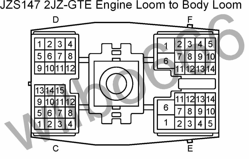
Big Gray Aristo Plug REFERENCE INFO - Configuration ( Plug , Pin , Symbol , Definition , Input/Output , What , Why , How )
C , 1 , Air Conditioning ECU: SSR- , Air Conditioning Compressor Speed Sensor, Output, The body loom side of this pin connects to the AC control ECU 'SSR-' input ,
The engine loom side of this pin connects to the AC compressor speed sensor mounted on the AC compressor.
C , 2, Air Conditioning ECU: SSR+, Air Conditioning Compressor Speed Sensor, Output, The body loom side of this pin connects to the AC control ECU 'SSR+' input, The engine loom side of this pin connects to the AC compressor speed sensor mounted on the AC compressor.
C , 3, Traction Control ECU: , A Traction Control Throttle Actuator, Output, The body loom side of this pin connects to the traction control ECU 'A' pin., The engine loom side of this pin connects to the traction control throttle actuator motor.
C , 4, Traction Control ECU: / , A Traction Control Throttle Actuator, Output, The body loom side of this pin connects to the traction control ECU '/A' pin., The engine loom side of this pin connects to the traction control throttle actuator motor.
C , 5, AC Magnetic Clutch, Input, The body loom side of this pin needs to be connected to the AC magnetic clutch relay switched power output which switches battery voltage to the AC magnetic clutch to energise the clutch and turn the AC on, The engine loom side of this pin connects to the AC magnetic clutch. The AC magnetic clutch is grounded via the engine block.
C , 6, Traction Control ECU: ACM, Traction Control Throttle Actuator, Input, The body loom side of this pin connects to the traction control ECU 'ACM' pin. , The engine loom side of this pin connects to the traction control throttle actuator motor.
C , 7, Traction Control ECU: B, Traction Control Throttle Actuator, Output, The body loom side of this pin connects to the traction control ECU 'B' pin., The engine loom side of this pin connects to the traction control throttle actuator motor.
C , 8, Traction Control ECU: /B, Traction Control Throttle Actuator, Output, The body loom side of this pin connects to the traction control ECU '/B' pin., The engine loom side of this pin connects to the traction control throttle actuator motor.
C , 9 / / / /
C , 10 / / / /
C , 11 , Traction Control ECU: BCM, Traction Control Throttle Actuator, Input, The body loom side of this pin connects to the traction control ECU 'BCM' pin., The engine loom side of this pin connects to the traction control throttle actuator motor.
C , 12, Traction Control ECU: GND, Traction Control Throttle Actuator, Output, The body loom side of this pin connects to the traction control ECU 'GND' pin to terminate the cable shield for the traction control throttle actuator motor., The engine loom side of this pin connects to the traction control throttle actuator motor cable shield.
C , 13, Hydraulic Cooling Fan ECU: SOL+, Hydraulic Cooling Fan Solenoid, Input, The body loom side of this pin connects to the hydraulic cooling fan ECU 'SOL+' output., The engine loom side of this pin connects to the hydraulic cooling fan control solenoid which is mounted on the water pump.
C , 14, / / / /
C , 15, Engine Mounted Diagnostic Connector: FP, Fuel Pump Power, Input, The body loom side of this pin needs to be connected to the positive side of the fuel pump wiring., The engine loom side of this pin connects to the diagnostic connector mounted on the side of the engine to allows power to be directly applied to the fuel pump in order to test its functionality.
D , 1, Low Oil Level Switch, Output, The body loom side of this pin connects to the low oil level light located in the dash., The engine loom side of this pin connects to the low oil level switch located at the sump on the front, intake side of the engine.
D , 2, Engine ECU: S2 , Cruise Control ECU: ECT, Automatic Transmission No.2 Shift Solenoid, Output, The body loom side of this pin connects to the cruise control ECU 'ECT' pin., The engine loom side of this pin connects to the engine ECU 'S2' output pin.
D , 3 / / / /
D , 4, Engine Mounted Diagnostic Connector: AB, SRS Airbag Power, Input, The body loom side of this pin connects to the SRS airbag control ECU 'LA' pin., The engine loom side of this pin connects to the diagnostic connector mounted on the side of the engine.
D , 5, Engine Mounted Diagnostic Connector: TEM, TEMS, Input, The body loom side of this pin connects to the TEMS control ECU 'TEM' pin., The engine loom side of this pin connects to the diagnostic connector mounted on the side of the engine.
D , 6, Engine ECU: IDL2, Traction Control Throttle Open Switch, Output, The body loom side of this pin connects to the traction control ECU. The engine loom side of this pin is connected to the traction control TPS and connects to Ground when the traction control throttle is in the idle (fully open) position.
D , 7, Engine Mounted Diagnostic Connector: WA, ABS, Input, The body loom side of this pin connects to the ABS control ECU 'WA' pin and also the ABS light mounted in the dash., The engine loom side of this pin connects to the diagnostic connector mounted on the side of the engine. Note that there is a shorting link inserted between terminals WA and WB of the diagnostic connector.
D , 8, Engine Mounted Diagnostic Connector: CCO, Exhaust Gas Temperature Sensor, Output, The body loom side of this pin needs to be connected to the engine ECU 'CCO' pin (Pin 29 on the 40 pin engine ECU plug)., The engine loom side of this pin connects to the diagnostic connector mounted on the side of the engine.
D , 9, Hydraulic Cooling Fan ECU: SOL- , Hydraulic Cooling Fan Solenoid, Input, The body loom side of this pin connects to the hydraulic cooling fan ECU 'SOL-' output., The engine loom side of this pin connects to the hydraulic cooling fan control solenoid which is mounted on the water pump.
D , 10, Hydraulic Cooling Fan ECU: TH+ Engine Diagnostic Connector: OPT, Hydraulic Cooling Fan Thermistor, Output, The body loom side of this pin connects to the diagnostic connector mounted to the side of the engine., The engine loom side of this pin connects to the hydraulic cooling fan thermistor that is mounted in the lower tank of the radiator.
D , 11, Engine Mounted Diagnostic Connector: WB, ABS, Output, The body loom side of this pin connects to the ABS relay., The engine loom side of this pin connects to the diagnostic connector mounted on the side of the engine. Note that there is a shorting link inserted between terminals WA and WB of the diagnostic connector from factory.
D , 12 / / / /
E , 1 / / / /
E , 2, Engine ECU: W, Check Engine Light, Input, The body loom side of this pin needs to be connected to the engine ECU 'W' check engine light output pin (Pin 6 on the 40 pin engine ECU plug). Note that the engine ECU 'W' check engine light output pin also needs to be connected to the vehicles check engine light located in the dash., The engine loom side of this pin connects to the diagnostic connector mounted on the side of the engine.
E , 3, Engine ECU: +B, Main EFI Relay Switched Power, Input, The body loom side of this pin needs to be connected to the main EFI relay switched power output which switches battery voltage to the ISCV, VSVs, etc. The main EFI relay is switched via the engine ECU M-REL output pin. Note that this pin does NOT supply power to the engine ECU directly, the engine ECU '+B' and '+B1' pins (Pin 39 and 40 on the 40 pin engine ECU plug) also need to be connected to the main EFI relay switched power output. , The engine loom side of this pin connects to the ISCV, VSVs, etc power supply pins.
E , 4, Starter Signal, Input, The body loom side of this pin needs to be connected to battery voltage when the ignition switch is in the CRANK position., The engine loom side of this pin connects to one side of the automatic transmission park / neutral switch and also the engine ECU NSW pin., Refer to pin E5 for further information.
E , 5, Starter Motor Relay Trigger Signal, Output , The body loom side of this pin needs to be connected to the starter motor relay coil to turn the relay on when the ignition switch is in CRANK position and the automatic transmission park / neutral switch is in the park / neutral position., The engine loom side of this pin is connected to the automatic transmission part / neutral position switch and also the engine ECU STA pin., Refer to pin E4 for further information.
E , 6, ABS Control ECU: TC Cruise Control ECU: TC TEMS ECU: TC Climate Control ECU: TC, Test Connector, Input, The body loom side of this pin connects to the 'TC' pin on a number of control modules., The engine loom side of this pin connects to the diagnostic connector mounted on the side of the engine.
E , 7, Engine ECU: TE2, Test Enable, Input, The body loom side of this pin needs to be connected to the engine ECU 'TE2' input pin (Pin 19 on the 40 pin engine ECU plug)., The engine loom side of this pin connects to the diagnostic connector mounted on the side of the engine.
E , 8, Neutral Gear Automatic Transmission Position Switch Indicator, Output, The body loom side of this pin connects to the dash to indicate when Neutral has been selected., The engine loom side of this pin connects to automatic transmission shifter position switch mounted on the automatic transmission and outputs battery voltage when the automatic transmission shifter is in the Neutral position.
E , 9, Engine ECU: 2 , 2nd Gear Automatic Transmission Position Switch Indicator, Output, The body loom side of this pin needs to be connected to the engine ECU '2' input pin (Pin 9 on the 40 pin engine ECU plug)., The engine loom side of this pin connects to automatic transmission shifter position switch mounted on the automatic transmission and outputs battery voltage when the automatic transmission shifter is in the 2 position.
E , 10, Engine ECU: L, Low Gear Automatic Transmission Position Switch Indicator, Output, The body loom side of this pin needs to be connected to the engine ECU 'L' input pin (Pin 10 on the 40 pin engine ECU plug).. The engine loom side of this pin connects to automatic transmission shifter position switch mounted on the automatic transmission and outputs battery voltage when the automatic transmission shifter is in the L position.
E , 11, Drive Gear Automatic Transmission Position Switch Indicator, Output, The body loom side of this pin connects to the dash to indicate when Drive has been selected., The engine loom side of this pin connects to automatic transmission shifter position switch mounted on the automatic transmission and outputs battery voltage when the automatic transmission shifter is in the Drive position.
E , 12, Park Gear Automatic Transmission Position Switch Indicator, Output, The body loom side of this pin connects to the dash to indicate when Park has been selected., The engine loom side of this pin connects to automatic transmission shifter position switch mounted on the automatic transmission and outputs battery voltage when the automatic transmission shifter is in the Park position.
E , 13, Engine ECU: R, Reverse Gear Automatic Transmission Position Switch Indicator, Output, The body loom side of this pin needs to be connected to the engine ECU 'R' input pin (Pin 7 on the 40 pin engine ECU plug) and also the reverse lights., The engine loom side of this pin connects to automatic transmission shifter position switch mounted on the automatic transmission and outputs battery voltage when the automatic transmission shifter is in the Reverse position.
E , 14, Ignition Switched Power, Input, The body loom side of this pin needs to be connected to an ignition switched power source that supplies battery voltage when the ignition is in the RUN and CRANK Positions., The engine loom side of this pin connects switched battery voltage to the alternator, automatic transmission position switch, automatic transmission No.1 speed sensor and the reverse lights.
F , 1, Starter Motor Relay Switched Power, Input, The body loom side of this pin needs to be connected to the starter motor relay switched power output which switches battery voltage to the starter motor to turn it on and crank the engine. , The engine loom side of this pin connects to the starter motor solenoid. The starter motor is grounded via the engine block. , Refer to pins E4 & E5 for further information regarding the starter / starter relay circuit.
F , 2, No.1 Speed Sensor: Output Signal, Output, The body loom side of this pin needs to be connected to the speedometer located in the dash., The engine loom side of this pin connects to the automatic transmission No.1 speed sensor signal output pin.
F , 3, No.1 Speed Sensor: Ground, Input, The body loom side of this pin needs to be connected to pin F7 on this plug (Ground). In factory wiring this pin connects to the dash and the dash connects the speed sensor Ground pin (and other dash items) to Ground via a wire to pin F7 on this body loom plug, however this wiring can be simplified in engine transplant situations. Refer to pin F7 for further information., The engine loom side of this pin connects to the automatic transmission No.1 speed sensor Ground pin.
F , 4, Engine ECU: TE1, Test Enable, Input, The body loom side of this pin needs to be connected to the engine ECU 'TE1' input pin (Pin 20 on the 40 pin engine ECU plug). , The engine loom side of this pin connects to the diagnostic connector mounted on the side of the engine.
F , 5, Traction Control ECU: TS TEMS Control ECU: TS, Test Enable, Input, The body loom side of this pin connects to a number of control module 'TS' input pins., The engine loom side of this pin connects to the diagnostic connector mounted on the side of the engine.
F , 6, Ignition Switched Power to Coils, Igniter & Fuel Injectors, Input, The body loom side of this pin needs to be connected to a relay which is turned on when the ignition is in the RUN and CRANK positions to switch battery voltage to the coils, igniter and fuel injectors., The engine loom side of this pin connects to the coils, igniter and fuel injector power supply pins.
F , 7, Dash Ground & No.1 Speed Sensor Ground, Output, The body loom side of this pin is connected to the dash to supply a Ground. In factory wiring this pin connects to the dash and the dash connects the speed sensor Ground pin to Ground via a wire to this pin. However the automatic transmission No.1 speed sensor Ground wiring can be simplified in engine transplant situations by connecting pin F3 directly to this pin and not via the dash. Refer to pin F3 for further information., The engine loom side of this pin connects to Ground at the in take manifold.
F , 8, Low Oil Pressure Switch, Output, The body loom side of this pin needs to be connected to the low oil pressure light located in the dash., The engine loom side of this pin connects to the low oil pressure switch located on the front, lower, intake side of the engine.
F , 9, Engine Coolant Temperature Dash Sensor, Output, The body loom side of this pin needs to be connected to the coolant temperature gauge located in the dash., The engine loom side of this pin connect s to the one wire engine coolant temperature sensor located at the engine coolant water outlet to the radiator on the front, upper, exhaust side of the engine.
F , 10, Engine ECU: VF1, Voltage Feedback Diagnostics, Output, The body loom side of this pin connects to the under dash mounted diagnostic connector VF1 pin., The engine loom side of this pin connects to the engine ECU VF1 pin.
F , 11, Engine ECU: E1, Ground, Output The body loom side of this pin connects to the diagnostic connector mounted under the dash and the Ground side of the catalytic converter temperature sensor thermistor., The engine loom side of this pin connects to Ground at the intake manifold.
F , 12, Tachometer Output from Igniter, Output, The body loom side of this pin needs to be connected to the dash tachometer and other vehicle systems (e.g. hydraulic cooling fan ECU, etc)., The engine loom side of this pin connects to the igniter tachometer output pin which outputs a 0V to battery voltage signal that is related to engine RPM.
F , 13 / / / /
F , 14, Engine ECU: IDL1, Throttle Closed Switch, Output, The body loom side of this pin connects to the cruise control ECU, hydraulic cooling fan ECU, etc., The engine loom side of this pin is connected to the throttle TPS and connects to Ground when the throttle is in the idle (fully closed) position.
Last edited by gerrb; 01-31-14 at 04:11 PM.
01-31-14, 01:40 PM
#10
As I progress through the 2jzgte harness build for our SCs , there will be times that I remember bits and pieces of informations that may help so I will jump on the keyboard and write those cliff notes down before I forget them
a) Not all SC300 or SC400 throughout the years of their productions have EXACTLY the same wiring diagrams (schematics) . So don't make that assumption that they are all the same. There are differences in different years of SC300 and SC400 , so having the particular wiring diagram of your year and model will help a lot .
b) Not all year models of SC have the same color coding of wires too. So if you are relying on color coding of wires you be careful.
c) JDM wirings also have different color codes from USDM wirings . Like if you were piecing your parts together and got hold of a USDM 2jzgte harness from a MKIV , it has different color coding of wires from a JDM 2jzgte harness.
I know it is easier to look for wires referencing their colors but be careful. Knowing how to use a multi-tester or ohmeter to check resistance / continuity helps. It is not hard. If you buy a cheap multi-tester from harborfreight , I believe it has a small instruction phamplet. Using a multi-tester / ohmeter is for me a safer way of searching for a particular wire. Even that may not be foolproof . Like if your harness is still fully wrapped , you never know that some other wires are paralleled into that circuit so having a wiring diagram while tracing wires helps a lot too.
Last edited by gerrb; 01-31-14 at 01:43 PM.
01-31-14, 01:42 PM
#11
One thing you need to familiarize yourself really well , and I will stress it again REALLY WELL , is the orientation and numberiing of pins on the ecu and the connectors so you don't put / insert wires where they should not be. It is easy to make a mistake on this depending on how and which you are looking at
Let's start with the ECU pinout meaning looking at the pins on the ECU itself . I said ECU , not harness connector .
.
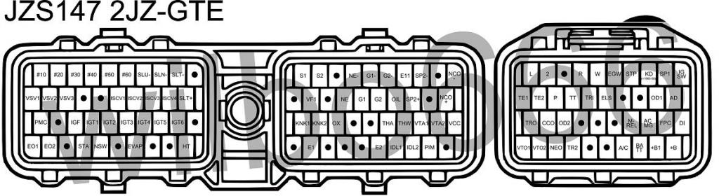
And this is the Actual ECU . IF you are looking on the pins of the ECU , for the 40 pin connector on the right , #1 starts on the right going left up to #10 , then #11 starts on the second row on the right and so on till 40 on the 4th row.
For the 80 pin connector , #1 starts on the right going left up to #20 (don't worry about the gap created by the bolt, pins 1-20 are the top row) ...then #21 starts on the second row on the right and so on till 80 on the 4th row.
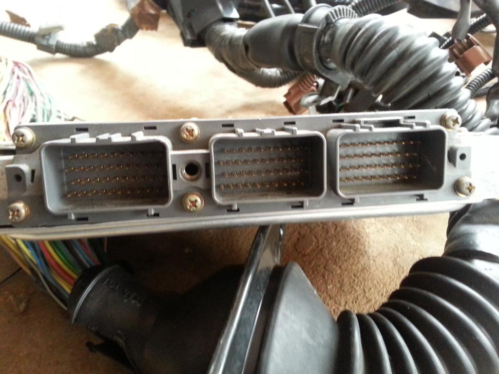
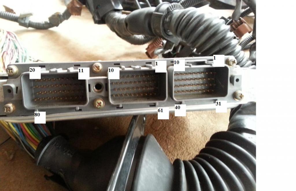
Take note , there is a bolt that separates the first set of 40 and the second set of 40 pins on the 80 pin connector . But it should be treated as one connector.
Again .. familiarize yourself well on this , cause once you are dealing with the harness itself , pin number orientations will differ and can be confusing and you may end up having wires in different places. Later on , I will show you , to add up to the confusion , on the 80 pin connector , there are numbers engraved that are not even the same as what I just mentioned thus adds up to the confusion.
Let's start with the ECU pinout meaning looking at the pins on the ECU itself . I said ECU , not harness connector
.And this is the Actual ECU . IF you are looking on the pins of the ECU , for the 40 pin connector on the right , #1 starts on the right going left up to #10 , then #11 starts on the second row on the right and so on till 40 on the 4th row.
For the 80 pin connector , #1 starts on the right going left up to #20 (don't worry about the gap created by the bolt, pins 1-20 are the top row) ...then #21 starts on the second row on the right and so on till 80 on the 4th row.


Take note , there is a bolt that separates the first set of 40 and the second set of 40 pins on the 80 pin connector . But it should be treated as one connector.
Again .. familiarize yourself well on this , cause once you are dealing with the harness itself , pin number orientations will differ and can be confusing and you may end up having wires in different places. Later on , I will show you , to add up to the confusion , on the 80 pin connector , there are numbers engraved that are not even the same as what I just mentioned thus adds up to the confusion.
Last edited by gerrb; 01-31-14 at 01:45 PM.
01-31-14, 01:44 PM
#12
By now , I hope you have familiarized yourself with the pin and numbering orientation on the ECU itself and have read the reference info on what each pin is for . If not, please do so because it will help you understand better what each wire is for and where they should go. IT WILL HELP A LOT I will assure you if you have a good understanding of the pinouts. It will also help you pinpoint which pins you will not use or will not need so you can delete / remove the wire or you can use it for something else. Like if you are on a Manual Transmission (v160,R154,W58 or any other) , the wiring for auto transmissions will not be needed. You, knowing which pins they are will make life easier for you. That is the reason I posted those JDM / Aristo ECU pinout INFO..
Once you are familiar with the ECU pin out , you will better understand what I would say next. A lot of people including me in the beginning got confused. I have been inserting pins / wires where they should not be. I only noticed it when one time I was looking for a certain number of pin and just to find out I already inserted a pin there so either the pin that was already in the plug was out of place or what I was holding should not be there.
Now , let's look at the actual 80 pin and 40 pin connectors .
This is how they look with the yellow covers
40 pin connector above the 80 pin connector
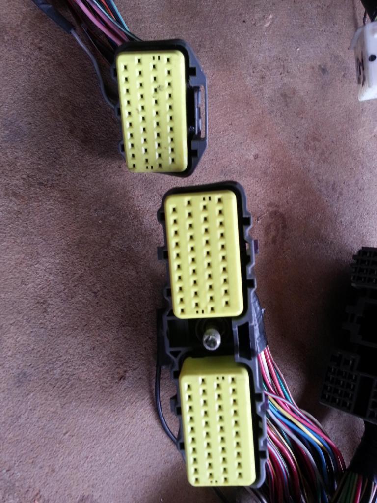
if you pry and remove those yellow covers , this is what you see.
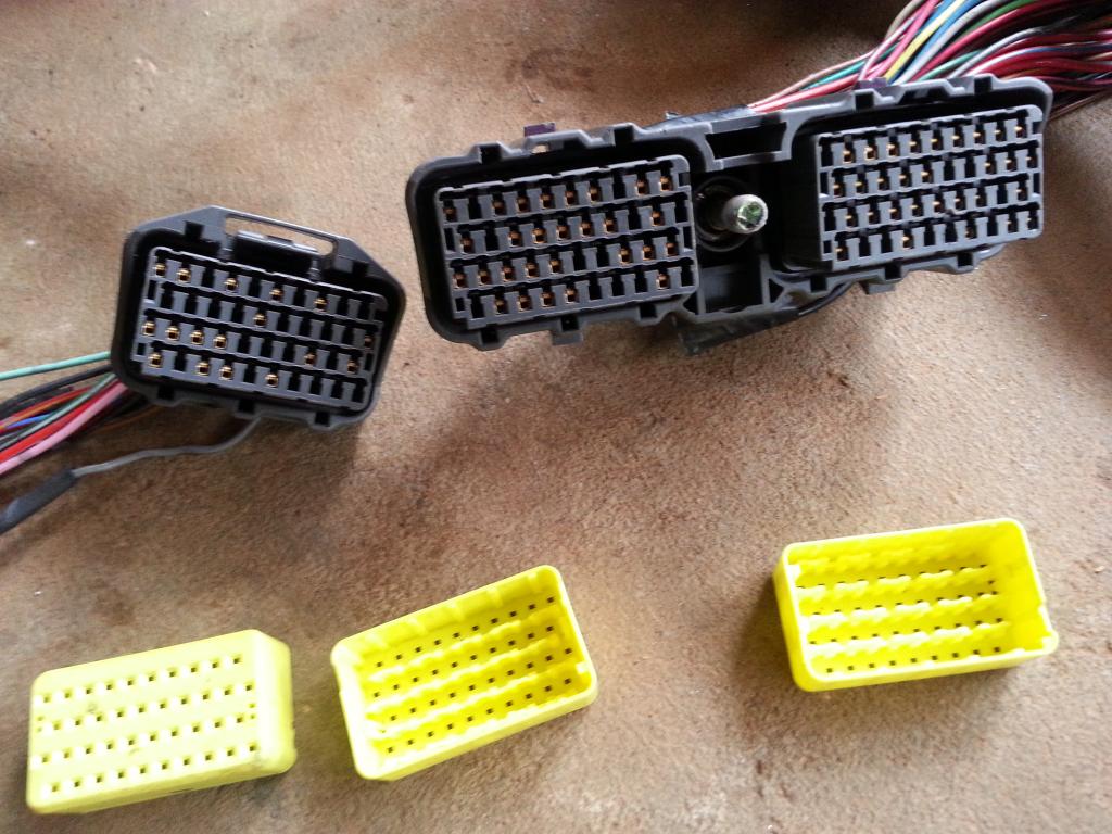
Now visualize how these connectors go into the ECU
they go this way
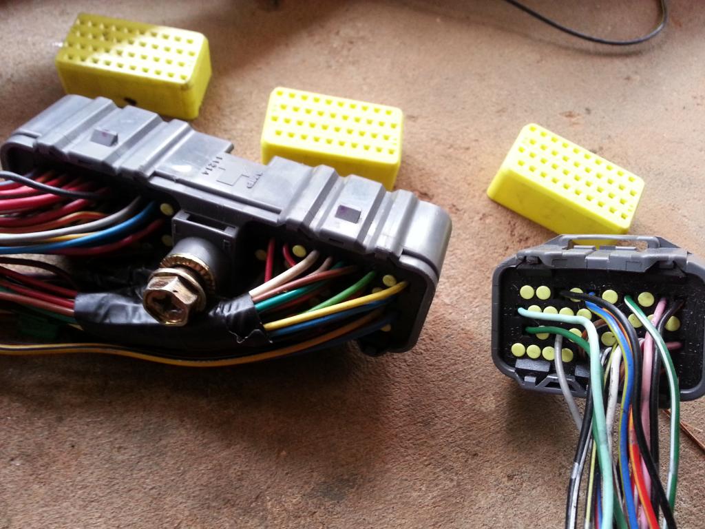
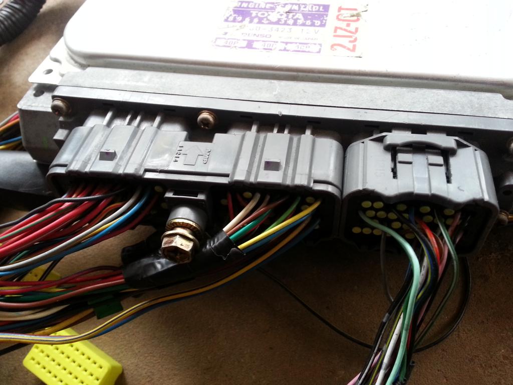
Now I guess you know where I am heading to . PIN Numbering orientation on the actual harness connectors is opposite with that of the ECU pinout.
for the 40 pin connector #1 starts on the left to #10 on the right and for the 80 pin connector #1 starts on the left and #20 to the right on the picture below

FROM NOW ON, you will be working on the harness , not the ecu , so you make sure you are fully aware which is let's say pin 21 of the 40 pin connector and which is pin 31 of the 80 pin connector of the HARNESS. It is on the harness where you will be inserting and removing pins so you make sure you know which is which so you don't inadvertently insert wires / pins on the wrong slot.
I hope I haven't created a lot of confusion so far. It is very important that you know which pin number you are working at ON THE HARNESS . For now , you can put aside the ECU pinning so you don't get confused. After all you will be modifying the HARNESS and not the ECU .
WHILE WORKING ON the 80 pin connector , there is something I want you to ignore on that connector cause it will just add up to the confusion .
Observe these pictures

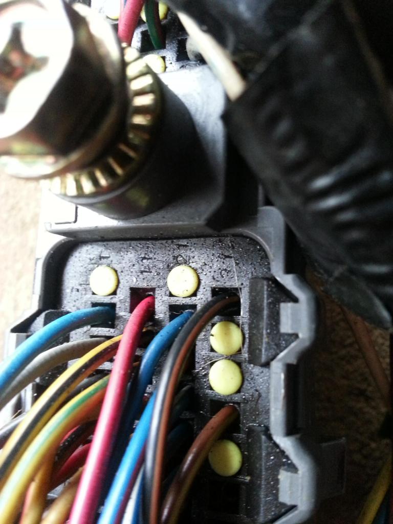
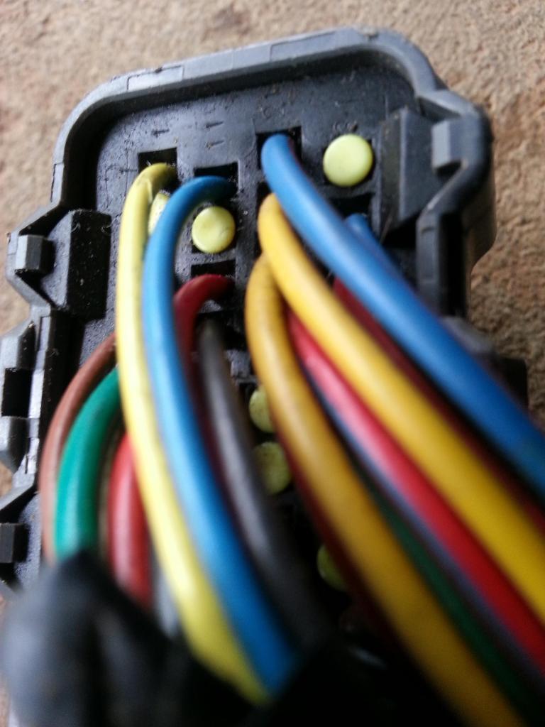
On that 80 pin connector , wire side , there are pin numbering embossed . They are not same as the way we have described them previously and the way we want them. On those embossed numbers , they have treated the 80 pin connector as two connectors that is why they have the numberings as 1 to 40 and another 1 to 40. FORGET ABOUT THAT , don't even reference to those numbers when you are moving wires around. REMEMBER 1 - 20 on the 80 pin connector is the top row and so on...so forth.
When you hold the 80 pin and 40 pin connectors of the harness , you should be able to tell the pin numbers which ever side of the connectors you are looking at . That helps a lot because you will be unlocking the pin on one side of the connector and you will be pulling the wire on the other side of the connector.
By now just by looking at this picture below , you should be able to pinpoint let's say pin 58 of the 80 pin ECU connector . I hope you see clearer now why I want you to be good in pinpointing pins. It is because you will be taking them out from their connectors.
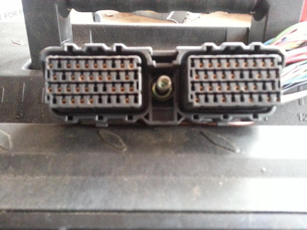
So for the 80 pin ECU connector , how do you do it ? Use a pointed tool to unlock the pin from the connector
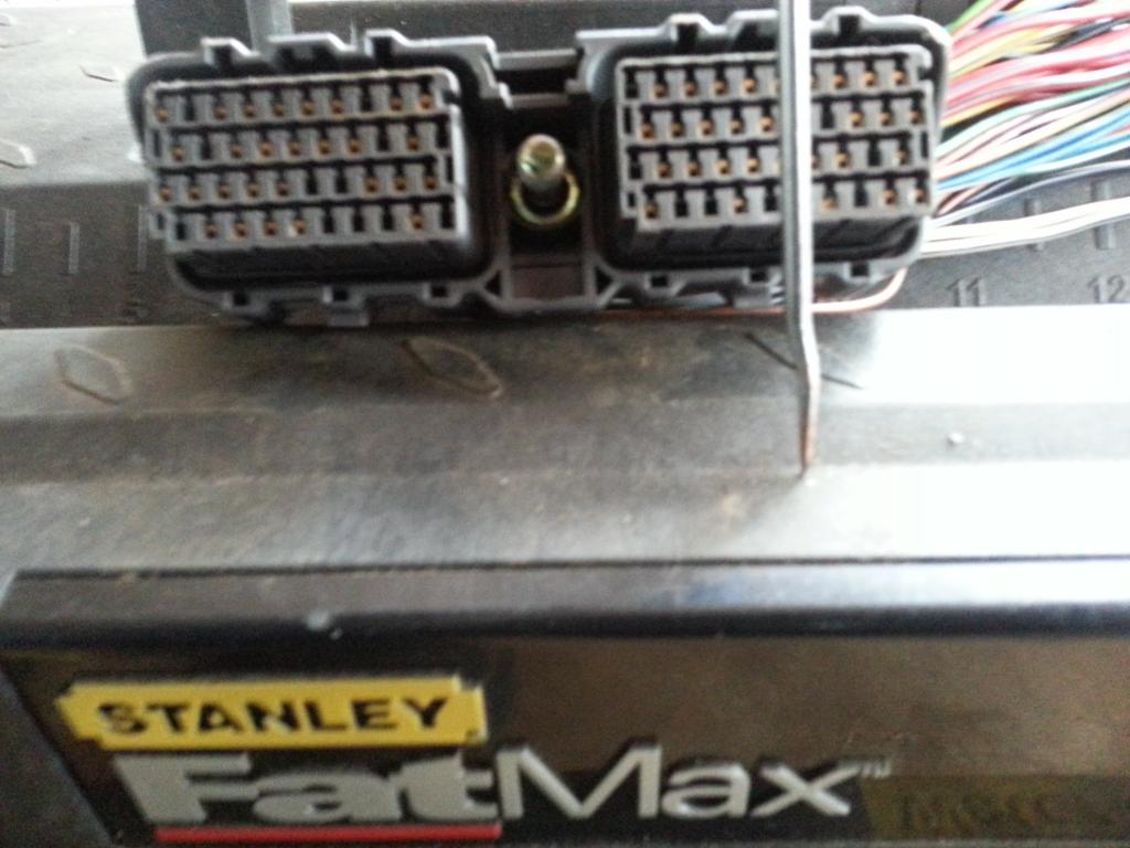
You need to insert it on the pin hole plug , let's say pin 58, trying to push that plastic holding that pin in place. Move that tool upwards or downwards depending on how you are holding that 80 pin connector. At the same time , you should be pulling the wire on the other side. Once you get the hang of it , it becomes easy. You may not be able to do it at one try but don't get discourage. It is easy.
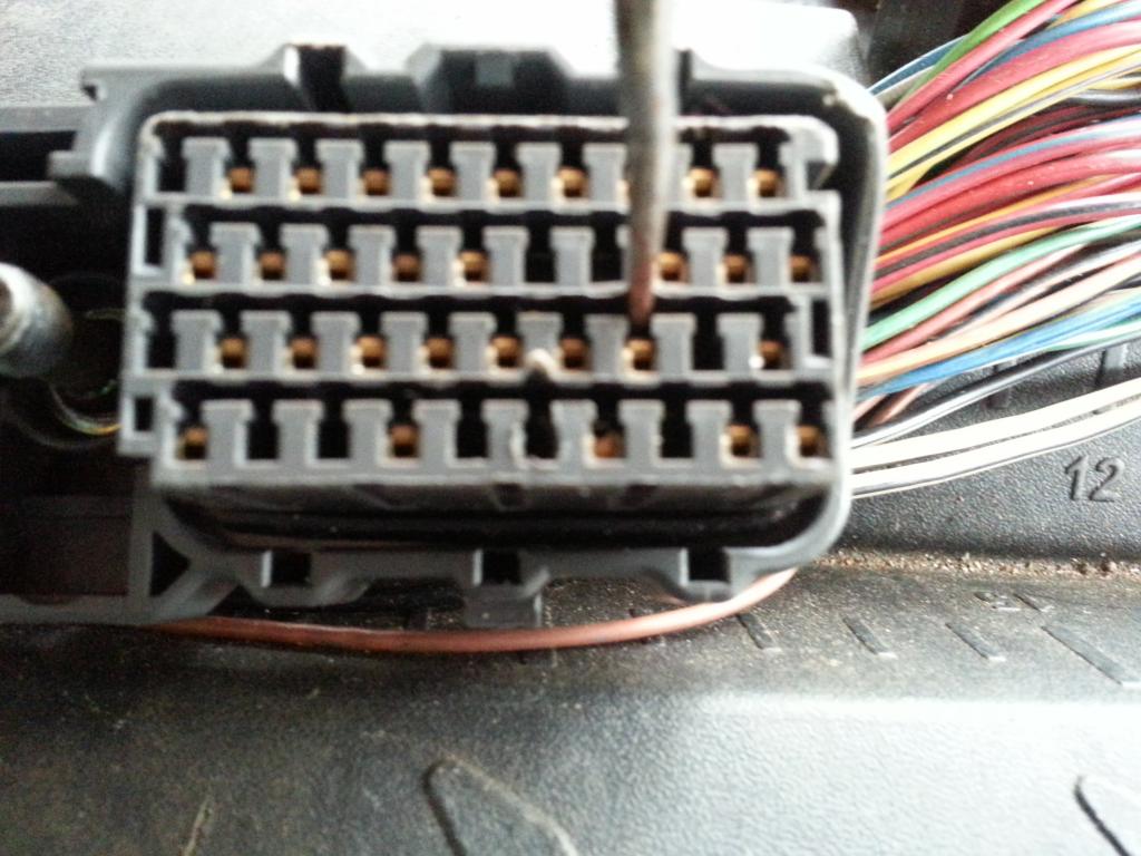
Here you go , the wire with its pin is out
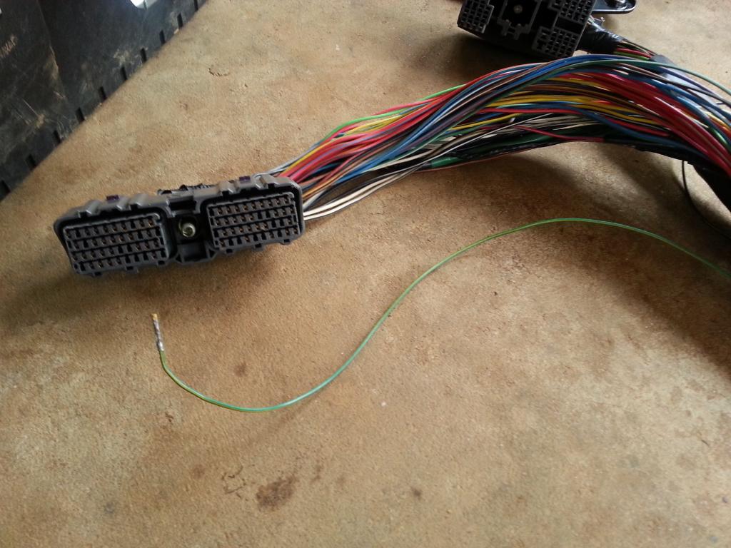
Observe closely the pin , there is a notch on the right side. That is what is holding it in place inside the connector. So when you pry that plastic lock inside , you can pull the wire/pin out.
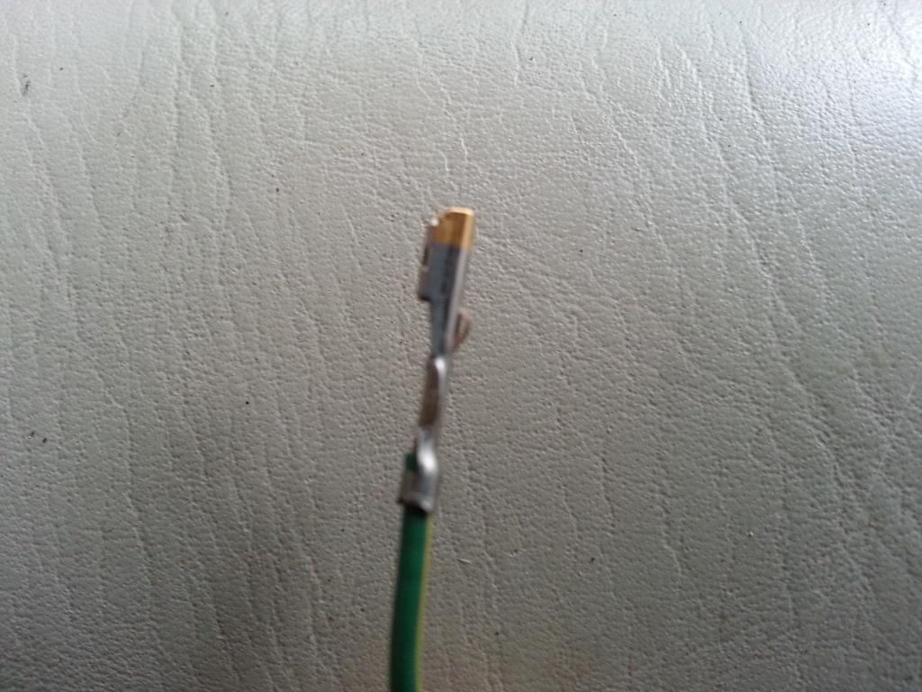
So how do you take out pins / wires from that Big Gray Aristo Plug on the Aristo 2jzgte harness ?
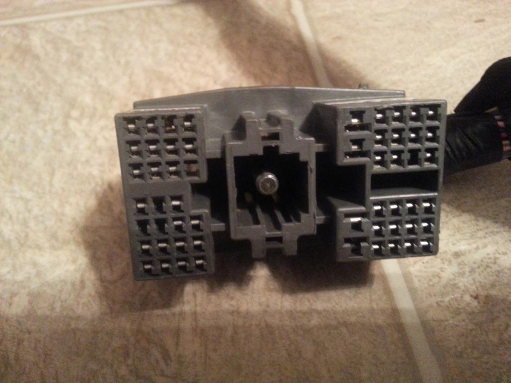
Every side of those C , D , E , F plugs have a lock ..white in color
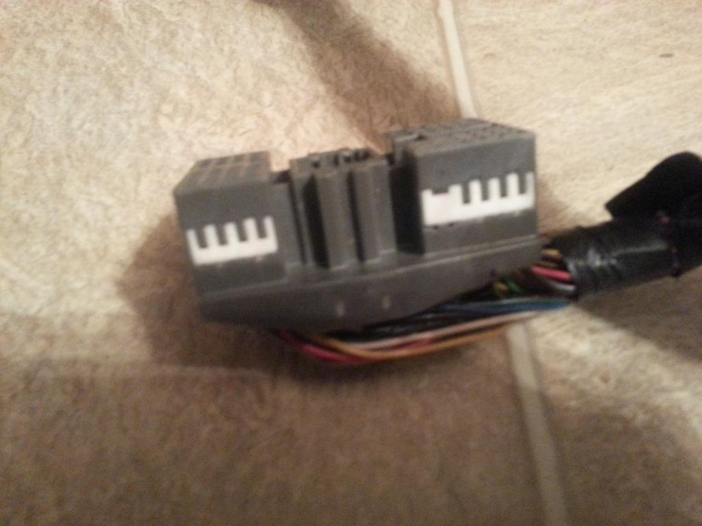
You need a sharp tool to pull that lock a bit .. it won't go far though ,
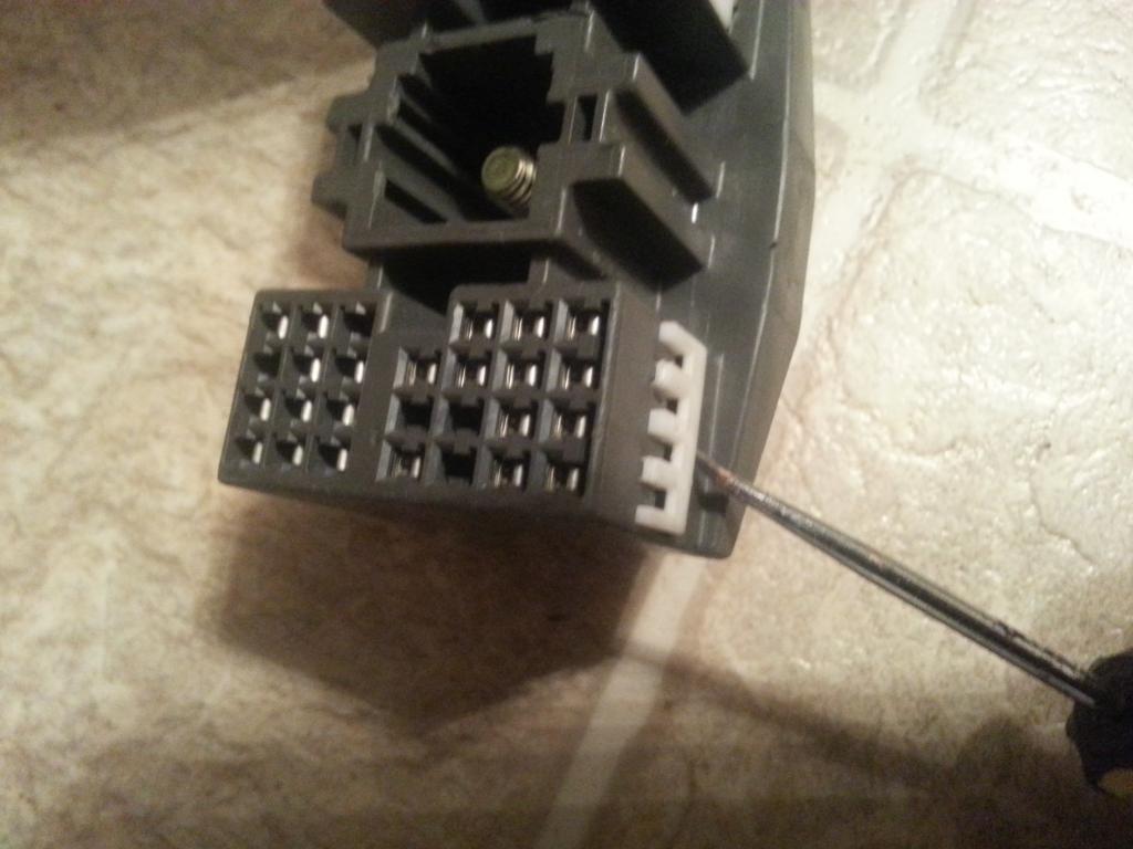
Now just like the 80 pin ECU connector , insert that sharp tool or paper clip and do an upward or downward motion depending on how you are holding that aristo gray plug (you are actually pushing that plastic clip inside that holds the pin) while you try to pull the wire/pin on the other side.
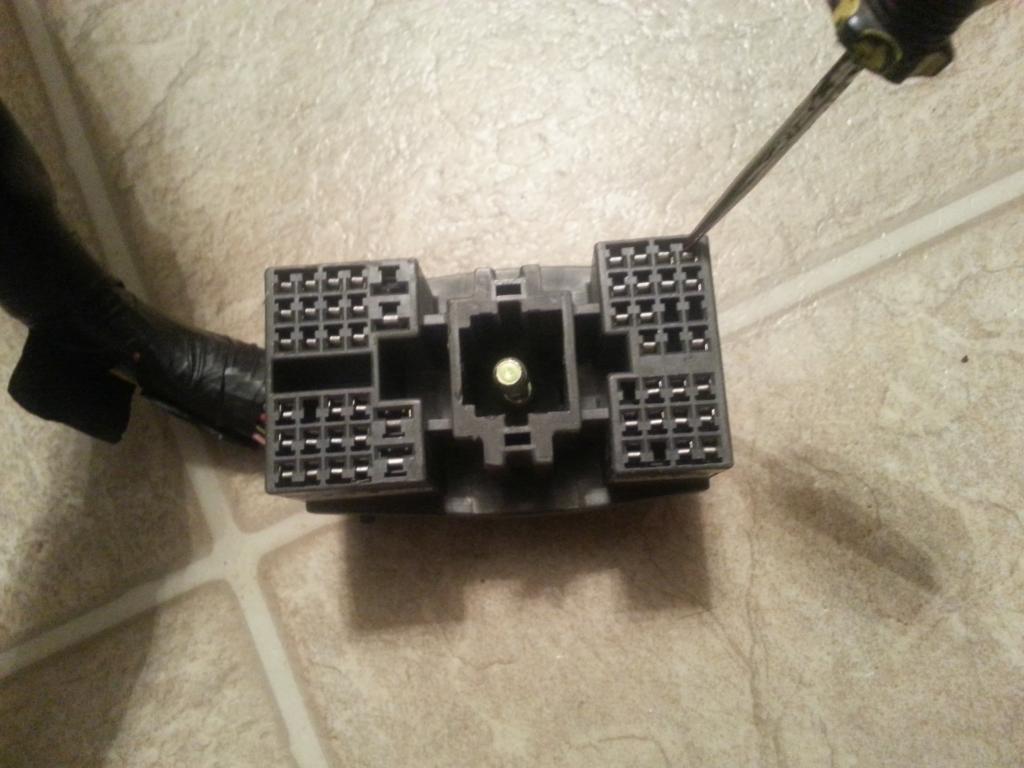
Once you are familiar with the ECU pin out , you will better understand what I would say next. A lot of people including me in the beginning got confused. I have been inserting pins / wires where they should not be. I only noticed it when one time I was looking for a certain number of pin and just to find out I already inserted a pin there so either the pin that was already in the plug was out of place or what I was holding should not be there.
Now , let's look at the actual 80 pin and 40 pin connectors .
This is how they look with the yellow covers
40 pin connector above the 80 pin connector

if you pry and remove those yellow covers , this is what you see.

Now visualize how these connectors go into the ECU
they go this way


Now I guess you know where I am heading to . PIN Numbering orientation on the actual harness connectors is opposite with that of the ECU pinout.
for the 40 pin connector #1 starts on the left to #10 on the right and for the 80 pin connector #1 starts on the left and #20 to the right on the picture below

FROM NOW ON, you will be working on the harness , not the ecu , so you make sure you are fully aware which is let's say pin 21 of the 40 pin connector and which is pin 31 of the 80 pin connector of the HARNESS. It is on the harness where you will be inserting and removing pins so you make sure you know which is which so you don't inadvertently insert wires / pins on the wrong slot.
I hope I haven't created a lot of confusion so far. It is very important that you know which pin number you are working at ON THE HARNESS . For now , you can put aside the ECU pinning so you don't get confused. After all you will be modifying the HARNESS and not the ECU .
WHILE WORKING ON the 80 pin connector , there is something I want you to ignore on that connector cause it will just add up to the confusion .
Observe these pictures


On that 80 pin connector , wire side , there are pin numbering embossed . They are not same as the way we have described them previously and the way we want them. On those embossed numbers , they have treated the 80 pin connector as two connectors that is why they have the numberings as 1 to 40 and another 1 to 40. FORGET ABOUT THAT , don't even reference to those numbers when you are moving wires around. REMEMBER 1 - 20 on the 80 pin connector is the top row and so on...so forth.
When you hold the 80 pin and 40 pin connectors of the harness , you should be able to tell the pin numbers which ever side of the connectors you are looking at . That helps a lot because you will be unlocking the pin on one side of the connector and you will be pulling the wire on the other side of the connector.
By now just by looking at this picture below , you should be able to pinpoint let's say pin 58 of the 80 pin ECU connector . I hope you see clearer now why I want you to be good in pinpointing pins. It is because you will be taking them out from their connectors.

So for the 80 pin ECU connector , how do you do it ? Use a pointed tool to unlock the pin from the connector

You need to insert it on the pin hole plug , let's say pin 58, trying to push that plastic holding that pin in place. Move that tool upwards or downwards depending on how you are holding that 80 pin connector. At the same time , you should be pulling the wire on the other side. Once you get the hang of it , it becomes easy. You may not be able to do it at one try but don't get discourage. It is easy.

Here you go , the wire with its pin is out

Observe closely the pin , there is a notch on the right side. That is what is holding it in place inside the connector. So when you pry that plastic lock inside , you can pull the wire/pin out.

So how do you take out pins / wires from that Big Gray Aristo Plug on the Aristo 2jzgte harness ?

Every side of those C , D , E , F plugs have a lock ..white in color

You need a sharp tool to pull that lock a bit .. it won't go far though ,

Now just like the 80 pin ECU connector , insert that sharp tool or paper clip and do an upward or downward motion depending on how you are holding that aristo gray plug (you are actually pushing that plastic clip inside that holds the pin) while you try to pull the wire/pin on the other side.

Last edited by gerrb; 01-31-14 at 01:48 PM.
01-31-14, 01:46 PM
#13
Each one has his own way of tackling the 2jzgte SC harness. Maybe some will start with the SC harness just like you see in other threads , take out what they don't need and then incorporate the 2jzgte wiring. Some will work on the 2jzgte wiring first and incorporate the SC plugs. I don't think there is any right or wrong there. It is all about personal preference. Which ever way you are comfortable and not get confused then go for it. What matters is at the end of the day , you have a working 2jzgte harness for your SC.
Just like I said , I like to start with the 2jzgte harness as my base because most of the plugs and wires you need for your engine are already there at the right places , done for you. That is the reason most of the info I have provided so far are about the 2jzgte harness and ECU .
Thus , I am cleaning up and working on that harness first .
These are two 2jzgte Aristo harnesses.
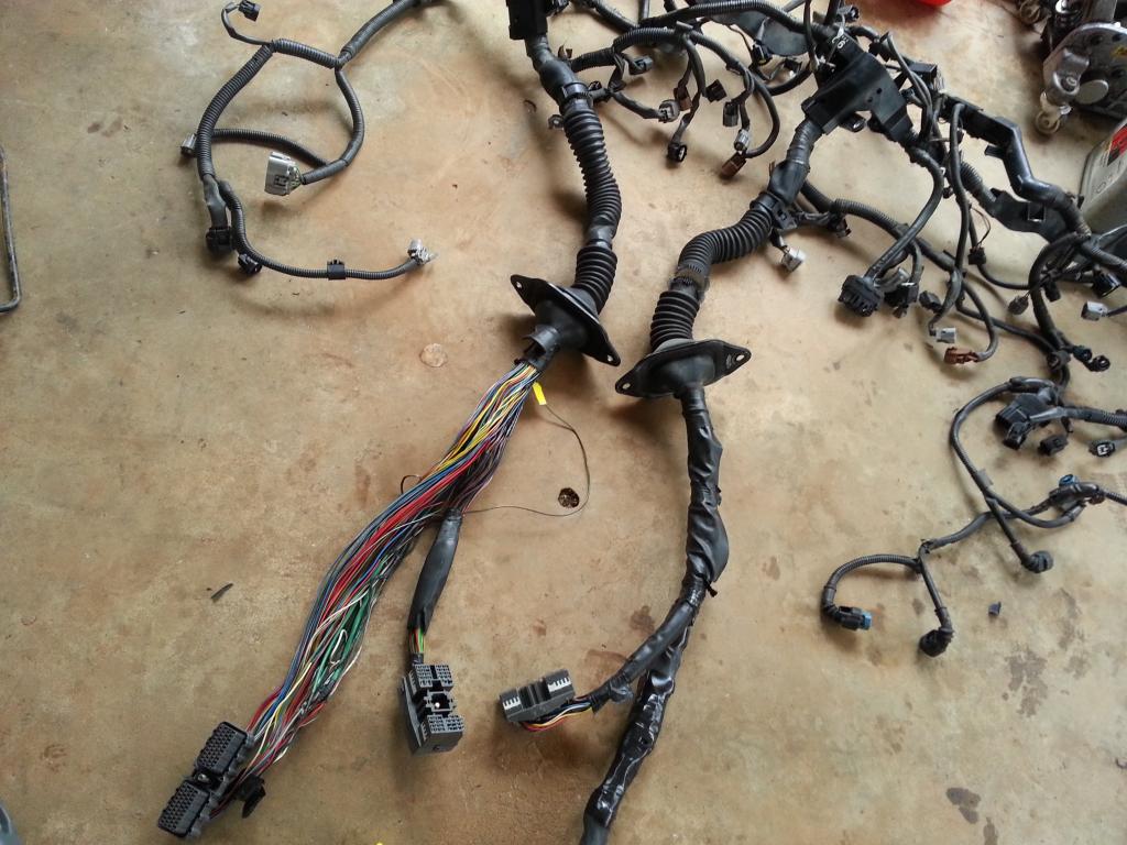
I took out the harness wrap up to a certain point but avoided spreading out the wires so it doesn't become messy. It is when all those wires start looking like a ball of sphagetti and getting messy that some people get all confused and give up . So be careful. Hey , for some as long as nobody touches what they are doing , regardless if it is messy , they are able to get away with it . Kudos to them.
I took out that metal bracket that bolts to an aristo firewall.
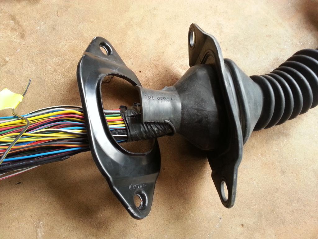
And cut that rubber wrap since I don't want it. If you want to reuse it , then save it by sliding it out of the plugs at the end but it is not easy.

I unwrapped it to that point for now because it is somewhere in that area where I will do the extending of wires.
In an Aristo 2jzgte harness, the igniter and noise filter plugs and wiring are on the passenger side strut tower that is the reason you find those connectors at the end of the harness. But on the MIKV with TT 2jzgte , whether USDM or JDM , the igniter and filter are on the driver side strut tower.
Some would like to put those connectors / wires just like where they are on the Supra MKIVs , on the driver strut tower. But I will personally leave them there since it saves me the trouble of relocating and messing with those plugs and wires. After all if you have seen my Red Mamba 1 engine bay , I hid that igniter and filter behind the passenger headlight. It is not even on the passenger strut tower. Less wires you see on the engine bay means cleaner look. Again that is a personal preference.
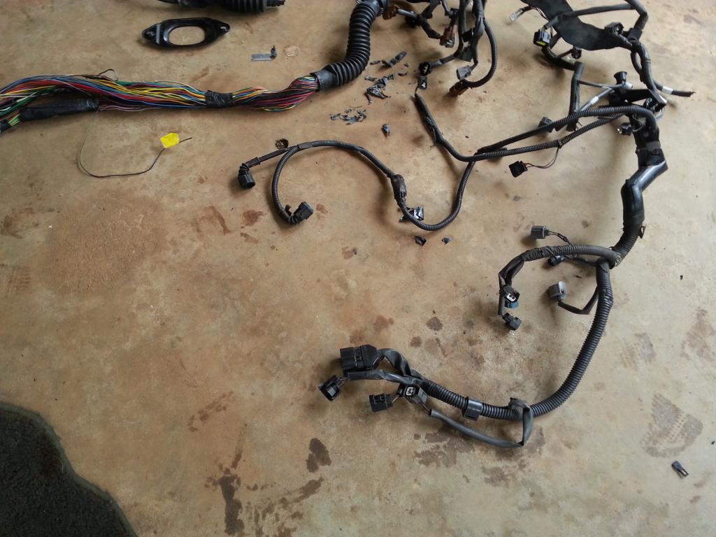
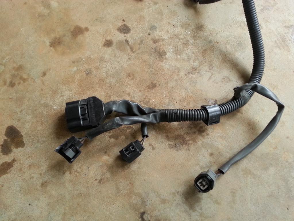
Are you ready to do THE DRILL ? Do you still remember it ? Damn , if you don't go back and memorize it. Know it by heart since you will be doing it a lot .
Let me refresh your memory about that drill.
A) Decide if you need the plug and wires depending on your particular setup .
..A1) IF YES ( that means you are keeping the plug ) , then
......A1a) Inspect the connector (plug) if it is physically damaged
......A1b) Replace that plug if its casing or lock is broken
......A1c) Go through all the wires of that plug
.........A1c1) Trace the wire by finding the pin from the plug where it goes to
............A1c11) If the wire ends at the 80 pin ECU connector OR Other Plug (except Big Gray Aristo Plug) then leave it where it is. That is where it should be anyway.
............A1c12) If the wire ends at the Big Gray Aristo Plug then pull it out from there and label it..
.........A1c2) If the wire ends at the 80 pin ECU connector OR Big Gray Aristo Plug then EXTEND IT otherwise you are not extending the wire.
.........A1c3) If the wire had been extended then Heat Shrink Wrap those solder points ( make sure no strand of wire is out of that heat shrink )
.........A1c4) Check connectivity between the two end points for that particular wire which you have just extended.
......A1d) Cover the wires of the plug with electrical tape and corrugated flexible hose once you are done with every single wire on that plug.
...A2) IF NO ( that means you are NOT keeping the plug ) and YOU ARE NOT KEEPING THE WIRES for future needs then start pulling the plug and its wires out
...A3) IF NO ( that means you are NOT keeping the plug ) BUT YOU ARE KEEPING THOSE WIRES for other components
......A3a) Remove the stock connector
......A3b) Extend the wires you are keeping and pull out the wires you do not need.
......A3c) Heat Shrink Wrap those solder points ( make sure no strand of wire is out of that heat shrink )
......A3d) Check connectivity between the two end points for that particular wire which you have just extended.
......A3e) Label the wire on both ends so you know it is an extra wire and which end point goes to the other end point
B) Update your CHART .
One thing I suggest , do things in phases and do it methodically . If you do things in an organized manner then you don't get confused. As much as possible , don't leave a group of connectors and wires you are working on till you have done everything you need to do with them .
Just like I said , I like to start with the 2jzgte harness as my base because most of the plugs and wires you need for your engine are already there at the right places , done for you. That is the reason most of the info I have provided so far are about the 2jzgte harness and ECU .
Thus , I am cleaning up and working on that harness first .
These are two 2jzgte Aristo harnesses.

I took out the harness wrap up to a certain point but avoided spreading out the wires so it doesn't become messy. It is when all those wires start looking like a ball of sphagetti and getting messy that some people get all confused and give up . So be careful. Hey , for some as long as nobody touches what they are doing , regardless if it is messy , they are able to get away with it . Kudos
to them.I took out that metal bracket that bolts to an aristo firewall.

And cut that rubber wrap since I don't want it. If you want to reuse it , then save it by sliding it out of the plugs at the end but it is not easy.

I unwrapped it to that point for now because it is somewhere in that area where I will do the extending of wires.
In an Aristo 2jzgte harness, the igniter and noise filter plugs and wiring are on the passenger side strut tower that is the reason you find those connectors at the end of the harness. But on the MIKV with TT 2jzgte , whether USDM or JDM , the igniter and filter are on the driver side strut tower.
Some would like to put those connectors / wires just like where they are on the Supra MKIVs , on the driver strut tower. But I will personally leave them there since it saves me the trouble of relocating and messing with those plugs and wires. After all if you have seen my Red Mamba 1 engine bay , I hid that igniter and filter behind the passenger headlight. It is not even on the passenger strut tower. Less wires you see on the engine bay means cleaner look. Again that is a personal preference.


Are you ready to do THE DRILL ? Do you still remember it ? Damn , if you don't
go back and memorize it. Know it by heart since you will be doing it a lot . Let me refresh your memory about that drill.
A) Decide if you need the plug and wires depending on your particular setup .
..A1) IF YES ( that means you are keeping the plug ) , then
......A1a) Inspect the connector (plug) if it is physically damaged
......A1b) Replace that plug if its casing or lock is broken
......A1c) Go through all the wires of that plug
.........A1c1) Trace the wire by finding the pin from the plug where it goes to
............A1c11) If the wire ends at the 80 pin ECU connector OR Other Plug (except Big Gray Aristo Plug) then leave it where it is. That is where it should be anyway.
............A1c12) If the wire ends at the Big Gray Aristo Plug then pull it out from there and label it..
.........A1c2) If the wire ends at the 80 pin ECU connector OR Big Gray Aristo Plug then EXTEND IT otherwise you are not extending the wire.
.........A1c3) If the wire had been extended then Heat Shrink Wrap those solder points ( make sure no strand of wire is out of that heat shrink )
.........A1c4) Check connectivity between the two end points for that particular wire which you have just extended.
......A1d) Cover the wires of the plug with electrical tape and corrugated flexible hose once you are done with every single wire on that plug.
...A2) IF NO ( that means you are NOT keeping the plug ) and YOU ARE NOT KEEPING THE WIRES for future needs then start pulling the plug and its wires out
...A3) IF NO ( that means you are NOT keeping the plug ) BUT YOU ARE KEEPING THOSE WIRES for other components
......A3a) Remove the stock connector
......A3b) Extend the wires you are keeping and pull out the wires you do not need.
......A3c) Heat Shrink Wrap those solder points ( make sure no strand of wire is out of that heat shrink )
......A3d) Check connectivity between the two end points for that particular wire which you have just extended.
......A3e) Label the wire on both ends so you know it is an extra wire and which end point goes to the other end point
B) Update your CHART .
One thing I suggest , do things in phases and do it methodically . If you do things in an organized manner then you don't get confused. As much as possible , don't leave a group of connectors and wires you are working on till you have done everything you need to do with them .
Last edited by gerrb; 01-31-14 at 01:50 PM.
01-31-14, 01:47 PM
#14
Before we start working on the farthest connectors , allow me to show you where the GROUND in FRONT of INTAKE MANIFOLD since you will be dealing with it.
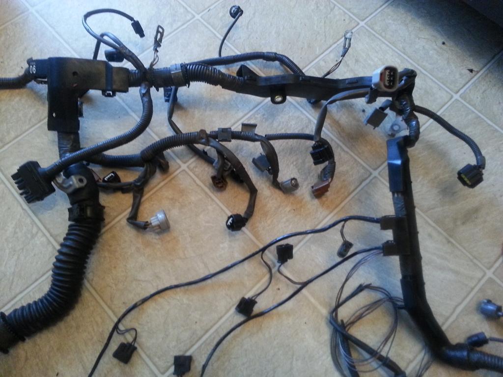
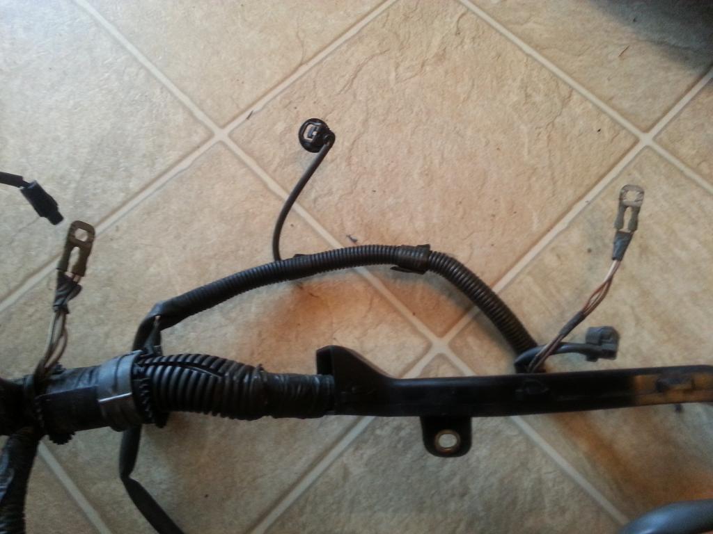
right at the center of this picture

Now let us explore the 4 connectors that are the farthest in relation to the ECU connectors.
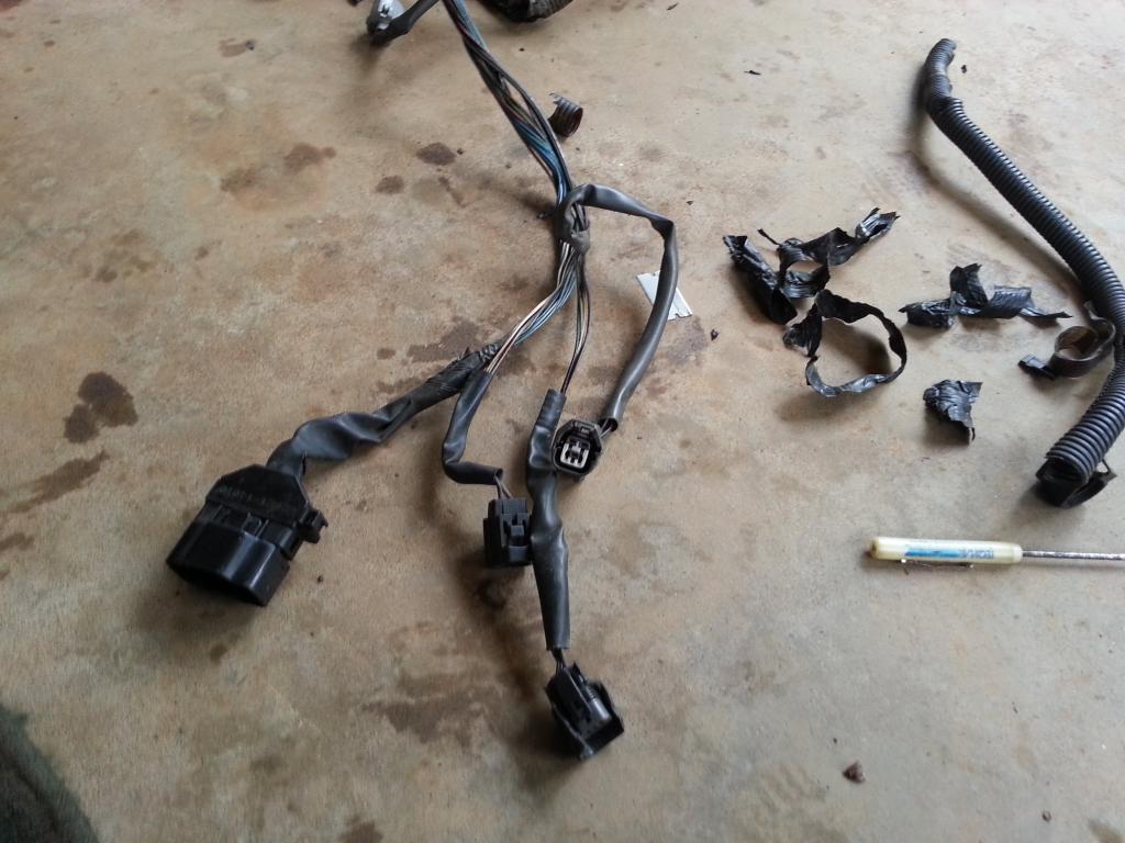
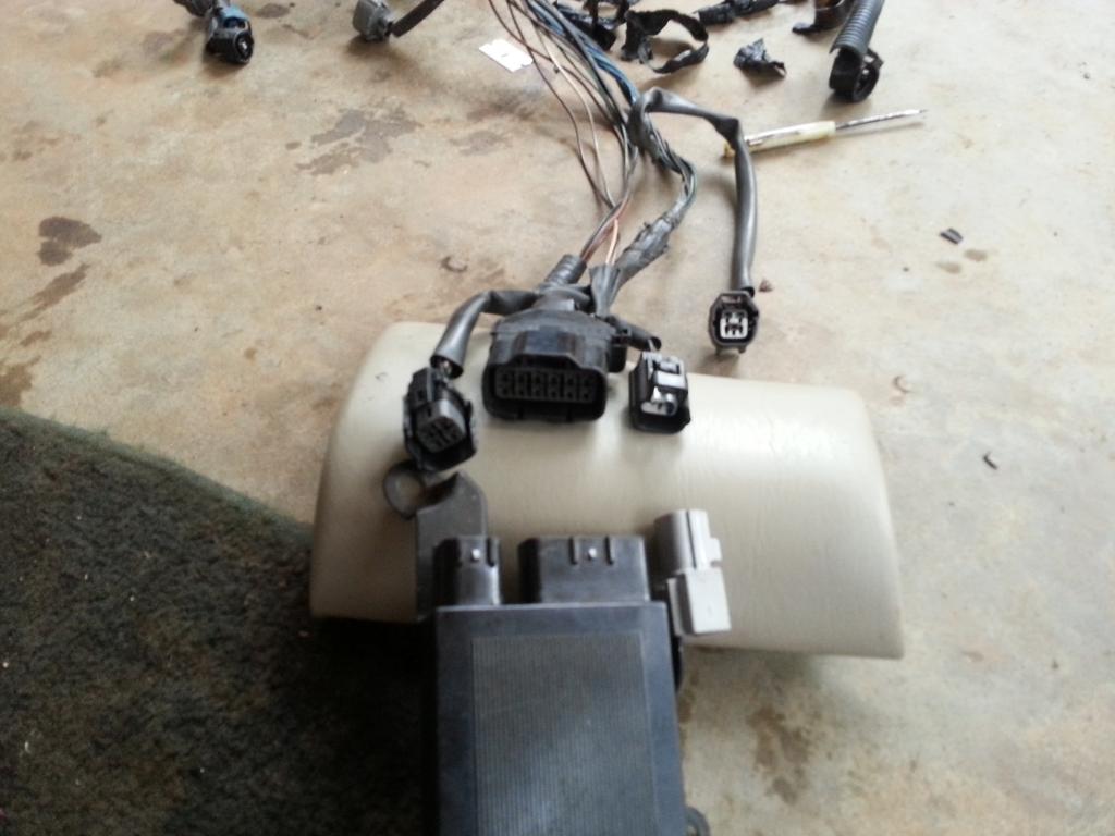
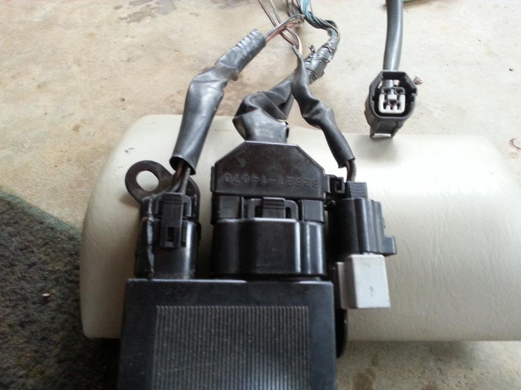
You need to know how to determine the pin numbering of component or sensor plugs . Usually , if you hold the connector in front of you with the lock on top , PIN #1 is top left and goes to the right then next row , left to right . Just like this one pictured..
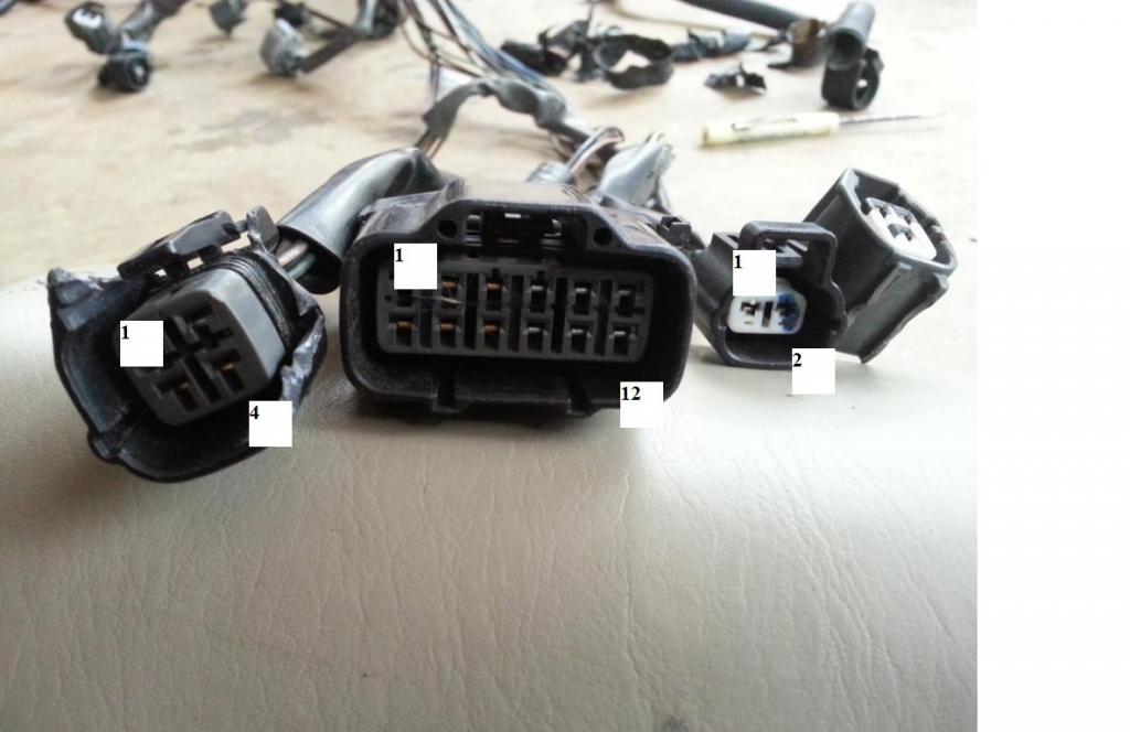
Knowing the pin numbering of each plug , you would know which pin you need to probe on one end connector and which pin to probe on the other end connector for your continuity tests.
I prefer to work on the connectors / wiring farthest first . Being old and brittle , I usually take out the old wraps. It is tough to route the wiring harness with old and brittle wraps. It doesn't have that flexibility anymore.
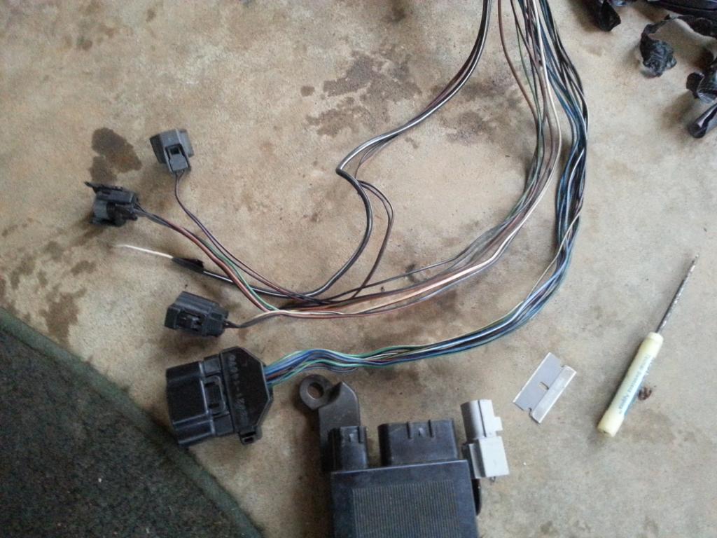
Among these 4 connectors we are currently working on , three of them you will need for your swap . For the Oxygen Sensor , it all depends whether you are going with a stock 2jzgte setup or are aiming for a high HP setup where most of the time the Oxygen Sensor is taken out.
Now before we do THE DRILL ( I do hope by now you know what THE DRILL is . ) , you need some INFO so you know which plug a particular wire goes to.
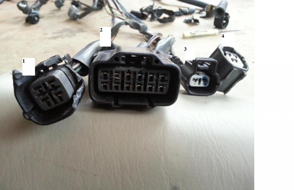
As pictured above we have
1) 4 pin Igniter Connector
Pin 1 of the 4 pin Igniter Connector goes to Pin 12 of Plug F of Aristo plug ( & should go to Pin 19 of the Data Link Connector & to ( SC3 IK1-8 , SC4 IK1-8 , MK4 ))
Pin 2 of the 4 pin Igniter Connector goes to Pin 6 of Plug F of Aristo plug & goes to Pin 1 of the Noise Filter ( & should go to ( SC3 IJ1-7 , SC4 EB2-2 , MK4 IJ1-1 or IJ1-9))
Pin 3 of the 4 pin Igniter Connector goes to Pin 58 of the 80 pin ECU Connector
Pin 4 of the 4 pin Igniter Connector goes to the Ground Connector on the Front Side of Intake Manifold & Pin 2 of the Noise filter Connector
2) 12 pin Igniter Connector
Pin 1 of the 12 pin Igniter Connector goes to Pin 57 of the 80 pin ECU Connector
Pin 2 of the 12 pin Igniter Connector goes to Pin 56 of the 80 pin ECU Connector
Pin 3 of the 12 pin Igniter Connector goes to Pin 55 of the 80 pin ECU Connector
Pin 4 of the 12 pin Igniter Connector goes to Pin 2 of the Ignition Coil Connector 3
Pin 5 of the 12 pin Igniter Connector goes to Pin 2 of the Ignition Coil Connector 2
Pin 6 of the 12 pin Igniter Connector goes to Pin 2 of the Ignition Coil Connector 1
Pin 7 of the 12 pin Igniter Connector goes to Pin 52 of the 80 pin ECU Connector
Pin 8 of the 12 pin Igniter Connector goes to Pin 53 of the 80 pin ECU Connector
Pin 9 of the 12 pin Igniter Connector goes to Pin 54 of the 80 pin ECU Connector
Pin 10 of the 12 pin Igniter Connector goes to Pin 2 of the Ignition Coil Connector 4
Pin 11 of the 12 pin Igniter Connector goes to Pin 2 of the Ignition Coil Connector 5
Pin 12 of the 12 pin Igniter Connector goes to Pin 2 of the Ignition Coil Connector 6
3) Noise Filter Connector
Pin 1 of the Noise Filter Connector goes to Pin 2 of the 4 pin Igniter Connector ( & should go to ( SC3 IJ1-7, SC4 EB2-2 , MK4 IJ1-1 or IJ1-9 ))
Pin 2 of the Noise Filter Connector goes to the Ground Connector on the Front Side of Intake Manifold & Pin 4 of the 4 pin Igniter Connector
4) Oxygen Sensor Connector (O2)
Pin 1 of the Oxygen Sensor goes to Pin 71 of the 80 pin ECU Connector
Pin 2 of the Oxygen Sensor goes to Pin 3 of Plug E of Aristo Plug ( & should go to Pin 12 of the Data Link Connector & to ( SC3 IJ1-12 & EB2-1 & Short-4 , SC4 IJ1-12 & EB2-3 , MK4 EA3-3 ))
Pin 3 of the Oxygen Sensor goes to Pin 48 of the 80 pin ECU Connector
Guys, you already should know by now which is pin 1 of every plug , and from the above given info , you will know where each wire should go. NOW, you can do THE DRILL .
For those who do not remember what is THE DRILL , let me write it again for the 3rd time
A) Decide if you need the plug and wires depending on your particular setup .
..A1) IF YES ( that means you are keeping the plug ) , then
......A1a) Inspect the connector (plug) if it is physically damaged
......A1b) Replace that plug if its casing or lock is broken
......A1c) Go through all the wires of that plug
.........A1c1) Trace the wire by finding the pin from the plug where it goes to
............A1c11) If the wire ends at the 80 pin ECU connector OR Other Plug (except Big Gray Aristo Plug) then leave it where it is. That is where it should be anyway.
............A1c12) If the wire ends at the Big Gray Aristo Plug then pull it out from there and label it..
.........A1c2) If the wire ends at the 80 pin ECU connector OR Big Gray Aristo Plug then EXTEND IT otherwise you are not extending the wire.
.........A1c3) Heat Shrink Wrap those solder points ( make sure no strand of wire is out of that heat shrink )
.........A1c4) Check connectivity between the two end points for that particular wire which you have just extended.
......A1d) Cover the wires of the plug with electrical tape and corrugated flexible hose once you are done with every single wire on that plug.
...A2) IF NO ( that means you are NOT keeping the plug ) and YOU ARE NOT KEEPING THE WIRES for future needs then start pulling the plug and its wires out
...A3) IF NO ( that means you are NOT keeping the plug ) BUT YOU ARE KEEPING THOSE WIRES for other components
......A3a) Remove the stock connector
......A3b) Extend the wires you are keeping and pull out the wires you do not need.
......A3c) Heat Shrink Wrap those solder points ( make sure no strand of wire is out of that heat shrink )
......A3d) Check connectivity between the two end points for that particular wire which you have just extended.
......A3e) Label the wire on both ends so you know it is an extra wire and which end point goes to the other end point
B) Update your CHART .
Let's go over the first plug we mentioned above in relation to THE DRILL so you will better understand how to go about the process .
1) 4 pin Igniter Connector - Do I need it for my setup ?
YES , so you need to inspect the physical condition of the plug. The picture below shows that it is broken so we need to replace it . Then go to every wire on this plug.
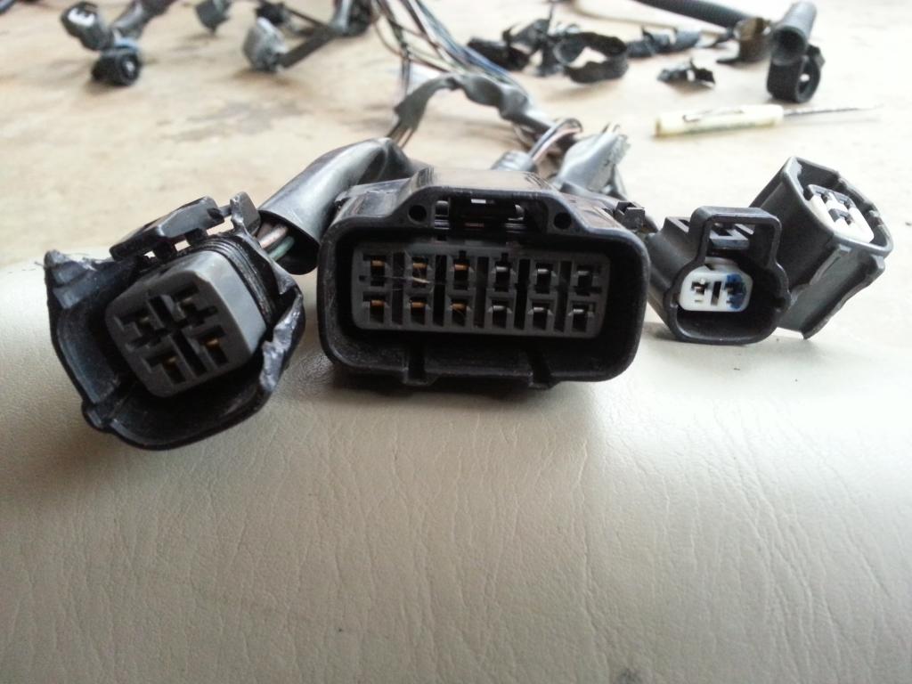
Find Pin 1 . Trace the wire on Pin 1. It goes to the Aristo plug so pull it out from that plug and label it AF12 so we know that it came out of pin 12 of plug F of the Aristo plug . Now you extend it , heat shrink wrap it , check the connectivity from pin 1 of the 4 pin Igniter Connector to this pin which you just labeled AF12. There should be connectivity if your solder points are good and there is no break on the line. If your connectivity is bad , find where the problem is and fix it till you get a good connectivity between the two end points. As seen on the info on parenthesis , this AF12 pin should go to the plugs written in parenthesis.They are body plugs. But we haven't covered them yet so you will go back on this one later thus the importance of proper labeling so you know which is which.
Proceed to Pin 2 . Trace the wire on Pin 2 . It goes to the Aristo plug so pull it out from that plug and label it AF6 so we know that it came out of pin 6 of plug F of the Aristo Plug. Now you extend it, heat shrink wrap it, check the connectivity from pin 2 of the 4 pin Igniter Connector to this pin which you just labeled AF6 and to pin 1 of the Noise Filter. There should be connectivity ..if none find out why and fix.
Proceed to Pin 3 . Trace the wire on Pin 3 . It goes to the 80 pin ECU connector so leave it there. Now you extend it, heat shrink wrap it, check the connectivity from pin 3 of the 4 pin Igniter Connector to pin 58 of the 80 pin ECU Connector. There should be connectivity ..if none find out why and fix.
Proceed to Pin 4 . Trace the wire on Pin 4 . It goes to the Ground connector on the Front Intake Manifold so leave it there. It doesn't need extending or shrink wrapping. Just check connectivity from Pin 4 of the 4 pin Igniter Connector to pin 2 of the Noise Filter. There should be connectivity , if none find out why and fix.
Once you are all done with the wires of that 4 pin Igniter plug which in this case we are , wrap the wires with electrical tape and corrugated flexible hose.
NOTE :
Allow me to explain something here. What are those in parenthesis found in some wire info lines ? They simply mean that the particular wire would be connected to those plugs in parenthesis. Right now we cannot connect the wire since we still don't have those plugs or connectors . Like that AF12 should go to pin 19 of the Data Link Connector and to pin 8 of IK1 for an SC300 / SC400 . There is no other connection for the MKIV for this wire since I didn't write any info for the MK4
Just to make things clearer , let's explain what is on parenthesis and bold characters for Pin 2 of the 4 pin Igniter Connector. They simply mean that the particular wire would be connected to those body plugs. Like for an SC300 it will go to body plug IJ1 pin 7 , for an SC400 it will go to plug EB2 pin 2 and for a MKIV it will go to body plug IJ1 pin 1 or pin 9.
Those are answers to the many people who ask this question -> What wires should go to the body plugs ?
You are now ready to go to the NEXT PLUG and DO THE DRILL . PLEASE do it to all the other 3 connectors we have enumerated above and whose info I have provided.
What is the objective of this process you might ask ?
1) You are extending all the wires that need to be extended on the Aristo 2jzgte harness.
2) You are trying to make sure that all plugs on that Aristo 2jzgte harness are good.
3) You are also trying to make sure that connectivity from one end to the other end of every wire on that Aristo 2jzgte harness is good.


right at the center of this picture

Now let us explore the 4 connectors that are the farthest in relation to the ECU connectors.


You need to know how to determine the pin numbering of component or sensor plugs . Usually , if you hold the connector in front of you with the lock on top , PIN #1 is top left and goes to the right then next row , left to right . Just like this one pictured..

Knowing the pin numbering of each plug , you would know which pin you need to probe on one end connector and which pin to probe on the other end connector for your continuity tests.
I prefer to work on the connectors / wiring farthest first . Being old and brittle , I usually take out the old wraps. It is tough to route the wiring harness with old and brittle wraps. It doesn't have that flexibility anymore.

Among these 4 connectors we are currently working on , three of them you will need for your swap . For the Oxygen Sensor , it all depends whether you are going with a stock 2jzgte setup or are aiming for a high HP setup where most of the time the Oxygen Sensor is taken out.
Now before we do THE DRILL ( I do hope by now you know what THE DRILL is . ) , you need some INFO so you know which plug a particular wire goes to.

As pictured above we have
1) 4 pin Igniter Connector
Pin 1 of the 4 pin Igniter Connector goes to Pin 12 of Plug F of Aristo plug ( & should go to Pin 19 of the Data Link Connector & to ( SC3 IK1-8 , SC4 IK1-8 , MK4 ))
Pin 2 of the 4 pin Igniter Connector goes to Pin 6 of Plug F of Aristo plug & goes to Pin 1 of the Noise Filter ( & should go to ( SC3 IJ1-7 , SC4 EB2-2 , MK4 IJ1-1 or IJ1-9))
Pin 3 of the 4 pin Igniter Connector goes to Pin 58 of the 80 pin ECU Connector
Pin 4 of the 4 pin Igniter Connector goes to the Ground Connector on the Front Side of Intake Manifold & Pin 2 of the Noise filter Connector
2) 12 pin Igniter Connector
Pin 1 of the 12 pin Igniter Connector goes to Pin 57 of the 80 pin ECU Connector
Pin 2 of the 12 pin Igniter Connector goes to Pin 56 of the 80 pin ECU Connector
Pin 3 of the 12 pin Igniter Connector goes to Pin 55 of the 80 pin ECU Connector
Pin 4 of the 12 pin Igniter Connector goes to Pin 2 of the Ignition Coil Connector 3
Pin 5 of the 12 pin Igniter Connector goes to Pin 2 of the Ignition Coil Connector 2
Pin 6 of the 12 pin Igniter Connector goes to Pin 2 of the Ignition Coil Connector 1
Pin 7 of the 12 pin Igniter Connector goes to Pin 52 of the 80 pin ECU Connector
Pin 8 of the 12 pin Igniter Connector goes to Pin 53 of the 80 pin ECU Connector
Pin 9 of the 12 pin Igniter Connector goes to Pin 54 of the 80 pin ECU Connector
Pin 10 of the 12 pin Igniter Connector goes to Pin 2 of the Ignition Coil Connector 4
Pin 11 of the 12 pin Igniter Connector goes to Pin 2 of the Ignition Coil Connector 5
Pin 12 of the 12 pin Igniter Connector goes to Pin 2 of the Ignition Coil Connector 6
3) Noise Filter Connector
Pin 1 of the Noise Filter Connector goes to Pin 2 of the 4 pin Igniter Connector ( & should go to ( SC3 IJ1-7, SC4 EB2-2 , MK4 IJ1-1 or IJ1-9 ))
Pin 2 of the Noise Filter Connector goes to the Ground Connector on the Front Side of Intake Manifold & Pin 4 of the 4 pin Igniter Connector
4) Oxygen Sensor Connector (O2)
Pin 1 of the Oxygen Sensor goes to Pin 71 of the 80 pin ECU Connector
Pin 2 of the Oxygen Sensor goes to Pin 3 of Plug E of Aristo Plug ( & should go to Pin 12 of the Data Link Connector & to ( SC3 IJ1-12 & EB2-1 & Short-4 , SC4 IJ1-12 & EB2-3 , MK4 EA3-3 ))
Pin 3 of the Oxygen Sensor goes to Pin 48 of the 80 pin ECU Connector
Guys, you already should know by now which is pin 1 of every plug , and from the above given info , you will know where each wire should go. NOW, you can do THE DRILL .
For those who do not remember what is THE DRILL , let me write it again for the 3rd time
A) Decide if you need the plug and wires depending on your particular setup .
..A1) IF YES ( that means you are keeping the plug ) , then
......A1a) Inspect the connector (plug) if it is physically damaged
......A1b) Replace that plug if its casing or lock is broken
......A1c) Go through all the wires of that plug
.........A1c1) Trace the wire by finding the pin from the plug where it goes to
............A1c11) If the wire ends at the 80 pin ECU connector OR Other Plug (except Big Gray Aristo Plug) then leave it where it is. That is where it should be anyway.
............A1c12) If the wire ends at the Big Gray Aristo Plug then pull it out from there and label it..
.........A1c2) If the wire ends at the 80 pin ECU connector OR Big Gray Aristo Plug then EXTEND IT otherwise you are not extending the wire.
.........A1c3) Heat Shrink Wrap those solder points ( make sure no strand of wire is out of that heat shrink )
.........A1c4) Check connectivity between the two end points for that particular wire which you have just extended.
......A1d) Cover the wires of the plug with electrical tape and corrugated flexible hose once you are done with every single wire on that plug.
...A2) IF NO ( that means you are NOT keeping the plug ) and YOU ARE NOT KEEPING THE WIRES for future needs then start pulling the plug and its wires out
...A3) IF NO ( that means you are NOT keeping the plug ) BUT YOU ARE KEEPING THOSE WIRES for other components
......A3a) Remove the stock connector
......A3b) Extend the wires you are keeping and pull out the wires you do not need.
......A3c) Heat Shrink Wrap those solder points ( make sure no strand of wire is out of that heat shrink )
......A3d) Check connectivity between the two end points for that particular wire which you have just extended.
......A3e) Label the wire on both ends so you know it is an extra wire and which end point goes to the other end point
B) Update your CHART .
Let's go over the first plug we mentioned above in relation to THE DRILL so you will better understand how to go about the process .
1) 4 pin Igniter Connector - Do I need it for my setup ?
YES , so you need to inspect the physical condition of the plug. The picture below shows that it is broken so we need to replace it . Then go to every wire on this plug.

Find Pin 1 . Trace the wire on Pin 1. It goes to the Aristo plug so pull it out from that plug and label it AF12 so we know that it came out of pin 12 of plug F of the Aristo plug . Now you extend it , heat shrink wrap it , check the connectivity from pin 1 of the 4 pin Igniter Connector to this pin which you just labeled AF12. There should be connectivity if your solder points are good and there is no break on the line. If your connectivity is bad , find where the problem is and fix it till you get a good connectivity between the two end points. As seen on the info on parenthesis , this AF12 pin should go to the plugs written in parenthesis.They are body plugs. But we haven't covered them yet so you will go back on this one later thus the importance of proper labeling so you know which is which.
Proceed to Pin 2 . Trace the wire on Pin 2 . It goes to the Aristo plug so pull it out from that plug and label it AF6 so we know that it came out of pin 6 of plug F of the Aristo Plug. Now you extend it, heat shrink wrap it, check the connectivity from pin 2 of the 4 pin Igniter Connector to this pin which you just labeled AF6 and to pin 1 of the Noise Filter. There should be connectivity ..if none find out why and fix.
Proceed to Pin 3 . Trace the wire on Pin 3 . It goes to the 80 pin ECU connector so leave it there. Now you extend it, heat shrink wrap it, check the connectivity from pin 3 of the 4 pin Igniter Connector to pin 58 of the 80 pin ECU Connector. There should be connectivity ..if none find out why and fix.
Proceed to Pin 4 . Trace the wire on Pin 4 . It goes to the Ground connector on the Front Intake Manifold so leave it there. It doesn't need extending or shrink wrapping. Just check connectivity from Pin 4 of the 4 pin Igniter Connector to pin 2 of the Noise Filter. There should be connectivity , if none find out why and fix.
Once you are all done with the wires of that 4 pin Igniter plug which in this case we are , wrap the wires with electrical tape and corrugated flexible hose.
NOTE :
Allow me to explain something here. What are those in parenthesis found in some wire info lines ? They simply mean that the particular wire would be connected to those plugs in parenthesis. Right now we cannot connect the wire since we still don't have those plugs or connectors . Like that AF12 should go to pin 19 of the Data Link Connector and to pin 8 of IK1 for an SC300 / SC400 . There is no other connection for the MKIV for this wire since I didn't write any info for the MK4
Just to make things clearer , let's explain what is on parenthesis and bold characters for Pin 2 of the 4 pin Igniter Connector. They simply mean that the particular wire would be connected to those body plugs. Like for an SC300 it will go to body plug IJ1 pin 7 , for an SC400 it will go to plug EB2 pin 2 and for a MKIV it will go to body plug IJ1 pin 1 or pin 9.
Those are answers to the many people who ask this question -> What wires should go to the body plugs ?
You are now ready to go to the NEXT PLUG and DO THE DRILL . PLEASE do it to all the other 3 connectors we have enumerated above and whose info I have provided.
What is the objective of this process you might ask ?
1) You are extending all the wires that need to be extended on the Aristo 2jzgte harness.
2) You are trying to make sure that all plugs on that Aristo 2jzgte harness are good.
3) You are also trying to make sure that connectivity from one end to the other end of every wire on that Aristo 2jzgte harness is good.
Last edited by gerrb; 01-31-14 at 01:53 PM.
01-31-14, 01:49 PM
#15
At this point , you probably are done working on the four plugs we were supposed to be working on but allow me to share with you some pointers..
You will be asked to find pins either from the 80 pin ECU Connector , Big Gray Aristo Plug , Component plugs like the Igniter plug and later on from the body plugs and 40 pin ECU Connector. I guess by now you see the reason why I wanted you to educate yourself well in determining pin numbers from a plug. So, please make sure regardless of how you look at a connector , you will be able to point out a particular pin. Like just by looking at these connectors below , you should be able to pin point AF12 ( Pin 12 of Plug F of the Aristo Plug )
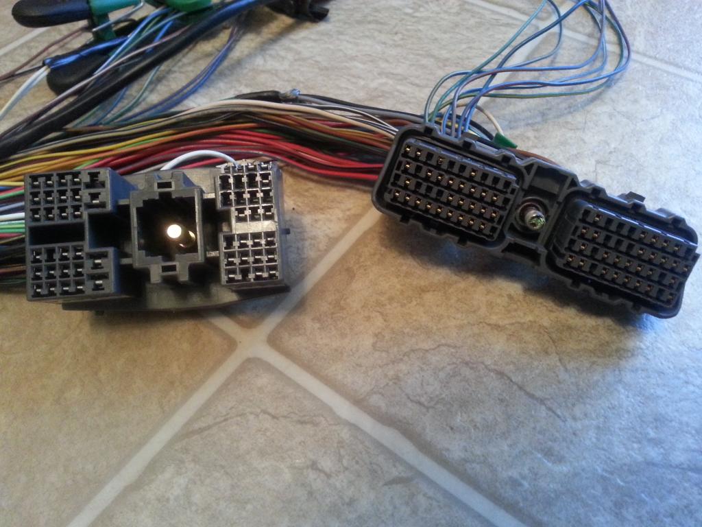
At this point unwrap the harness up to the part where you will do some cutting and extending of wires just to avoid getting all those wires in a mess.
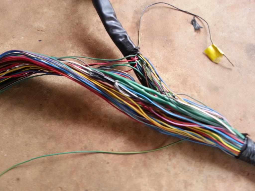
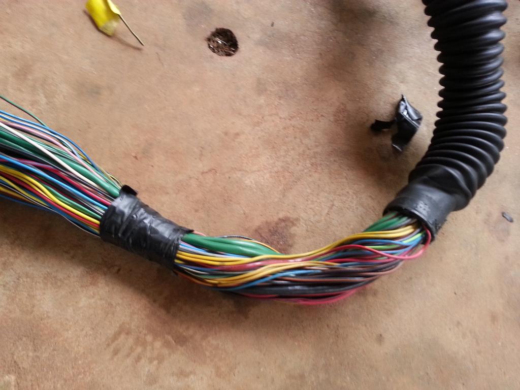
All your wires for extensions should be of the same length. If you decide to do an extension of 18" (inches) , then all those wires should be of that length.
So where will you cut that wire to insert that extension you might ask ?
Some suggestions :
* Don't cut too near the 80 pin plug
* Your extensions should be in staggered places so when you shrink wrap and cover the whole harness , it won't be bulging just in one place so much so that you cannot even insert the harness into the firewall plug
* If you can cut on a part of the harness which doesn't go inside the firewall and insert the extension there , better. Why ? You minimize bulging of the harness that goes into that little bitty firewall hole.
Last edited by gerrb; 01-31-14 at 01:56 PM.