2JZGTE Wiring Harness Made Easy
 01-31-14, 01:51 PM
#16

What do I mean when I say do the extensions in staggered areas ? Those wires were not cut and extended in exactly the same area. If I did , imagine how big that bunch of wires will be with the soldering , shrink wrapping and eventually whole harness cover / wrap.
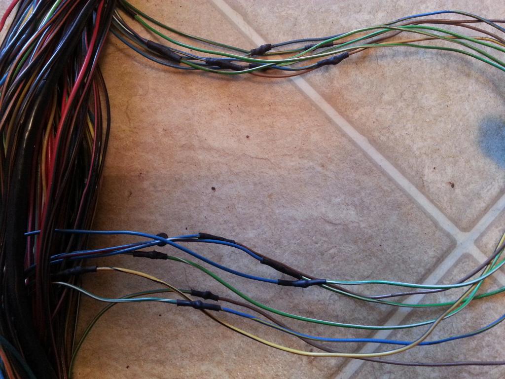
Since these wires go straight to the 80 pin connector and they are not shielded wires (I will talk about shielded wires later) , I decided to cut on the area of the harness that doesn't go through that firewall hole.
You have to use the right size of shrink wrap too and you don't need electrical tape as long as you don't puncture that shrink wrap that shields your solder point and prevent wires from being exposed. That is exactly why you shrink wrap solder points... to cover them. So when you are soldering and joining wires , make sure you dont have sharp areas or wires protruding. You also make sure that the shrink wrap is well heated and secured that it doesn't slide out of the solder point thus exposing the solder point.
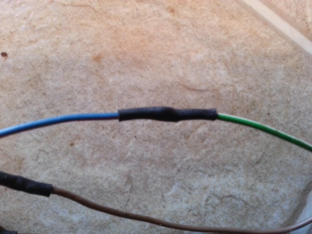
That's the beauty of cuts / solder points being in staggered positions too. Assuming you missed a wire protruding out of your shrink wrap , there is a possibility that it is away from other solder points avoiding possible shorts.
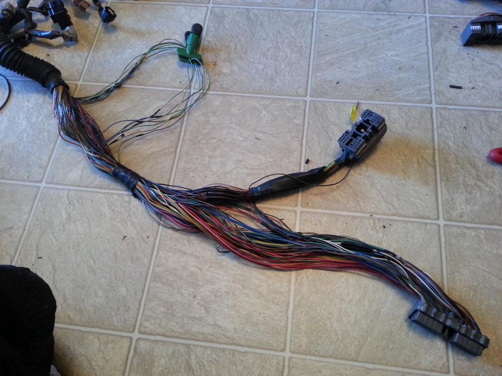
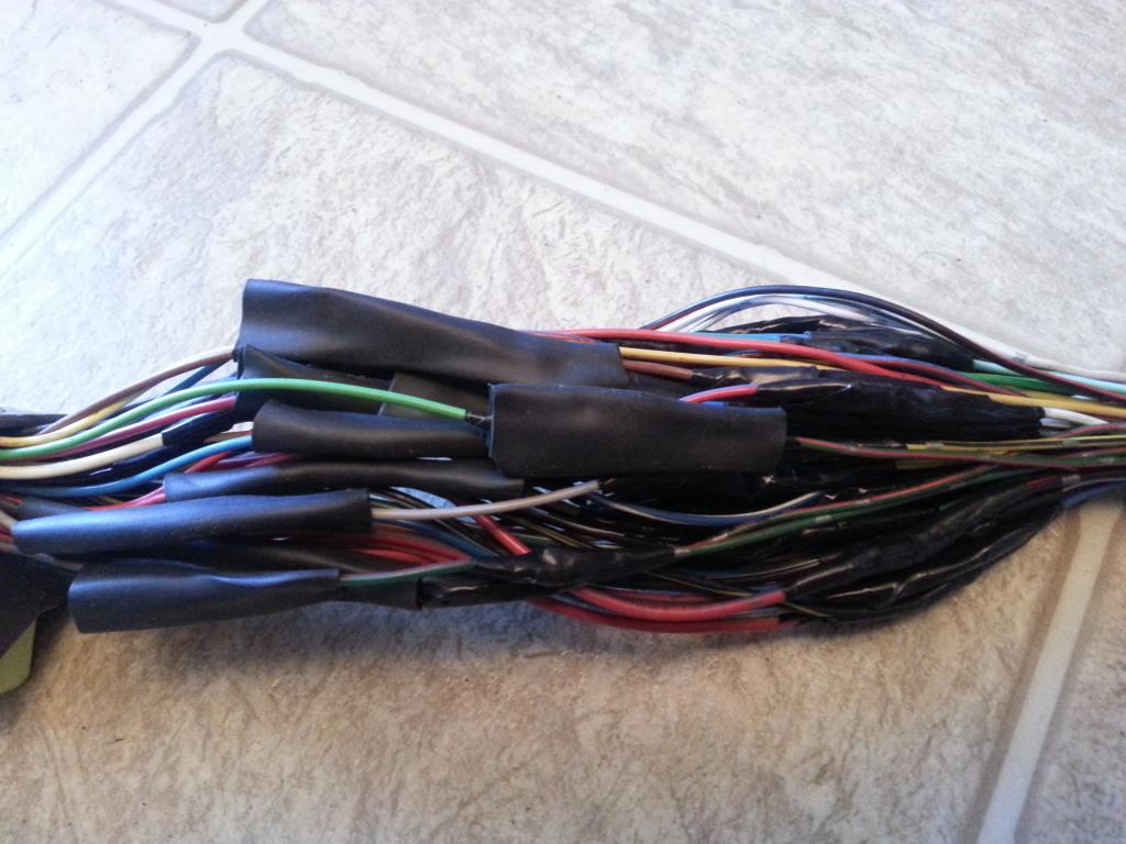
Sometime back I did help a friend who couldn't insert his harness into the firewall hole to get the harness into the foot well. This is the reason... , he used electrical tape and on top of the electrical tape , shrink wrap that were not the right sizes and most of all , the cutting of wires were so near each other so solder points where basically all in one place.
So for me , the picture below shows what you need to avoid :

Since these wires go straight to the 80 pin connector and they are not shielded wires (I will talk about shielded wires later) , I decided to cut on the area of the harness that doesn't go through that firewall hole.

You have to use the right size of shrink wrap too and you don't need electrical tape as long as you don't puncture that shrink wrap that shields your solder point and prevent wires from being exposed. That is exactly why you shrink wrap solder points... to cover them. So when you are soldering and joining wires , make sure you dont have sharp areas or wires protruding. You also make sure that the shrink wrap is well heated and secured that it doesn't slide out of the solder point thus exposing the solder point.

That's the beauty of cuts / solder points being in staggered positions too. Assuming you missed a wire protruding out of your shrink wrap , there is a possibility that it is away from other solder points avoiding possible shorts.
Sometime back I did help a friend who couldn't insert his harness into the firewall hole to get the harness into the foot well. This is the reason...
, he used electrical tape and on top of the electrical tape , shrink wrap that were not the right sizes and most of all , the cutting of wires were so near each other so solder points where basically all in one place.So for me , the picture below shows what you need to avoid :

Last edited by gerrb; 01-31-14 at 01:57 PM.
 01-31-14, 01:53 PM
#17
Please bear with me here. As I mentioned at the start of this harness build , it won't be a one sitting thing. I will work on the harness when I feel like it then document it on this thread. Now, I have decided to work on two harnesses at the same time... my harness for the Red Mamba 2 and that of my buddy Aaron.
It would be beneficial for this thread if I work on both harnesses at the same time and document them since one will be for manual transmission since Aaron is using an R154. That will help those who are doing a harness for a manual transmission like R154, W58 or V160 6 speed.
Mine for the RM2 should be a 6 speed V160 but I will make a harness with the auto trans wiring included so that people reading this thread who are building a harness for a swap with an auto transmission will get help too. What made me decide to keep my auto trans wiring ? It's because of a question I received and will answer in a Q&A post next . Besides , if I still have the auto trans wiring on my harness , if later I decide to install my ATF built Auto TT transmission , my harness is ready. Usually when you get a 2jzgte harness built with auto trans they are more expensive in the vicinity of $200 more. Why ? There are more wirings and consequently more work to be done.
So as mentioned , I am working on two harnesses at the same time when I feel like working on them so bear with me please. I know some are excited to get it done so they can work on theirs. I am doing exactly what I write here on two different harnesses. If there are differences between an auto or manual tranny harness I will point them out .

Last edited by gerrb; 01-31-14 at 02:01 PM.
01-31-14, 01:54 PM
#18
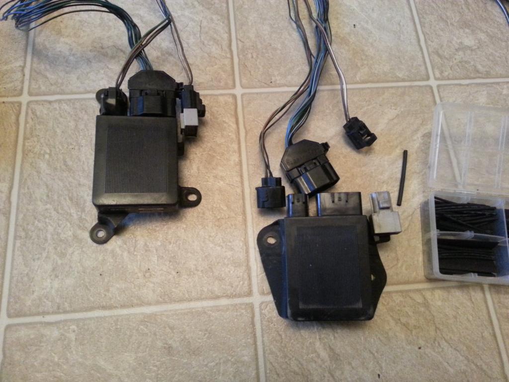
While I have these two SC300 harnesses intact , let me throw these pictures in here so to emphasize the point that not all SC300 wiring harnesses are the same and why the length of extension wires for your Aristo may vary . Put your aristo 2jzgte and sc300/sc400 side by side and see how much length you really need to extend the Aristo harness. In fact I got away extending only 12 inches a friend's harness. So the 16-22" was just really being very safe that's why I mentioned those numbers . You don't want your harness being short since it will be behind the AC blower and wont be able to connect the ECU. Being longer wont really do any harm after all. But if you are a perfectionist and wanted an exact lenght for wire extension. You need to do measurements on your Aristo and SC harness .. check their length difference.
These are two SC300 harness , observe their length from the firewall . Not exactly the same
One has more body plugs than the other. That is the reason having the particular year model wiring diagram for your car helps a lot. Not all Lexus SC wiring diagrams are same.
These are two SC300 harness , observe their length from the firewall . Not exactly the same


One has more body plugs than the other. That is the reason having the particular year model wiring diagram for your car helps a lot. Not all Lexus SC wiring diagrams are same.


Last edited by gerrb; 01-31-14 at 02:03 PM.
01-31-14, 01:58 PM
#19
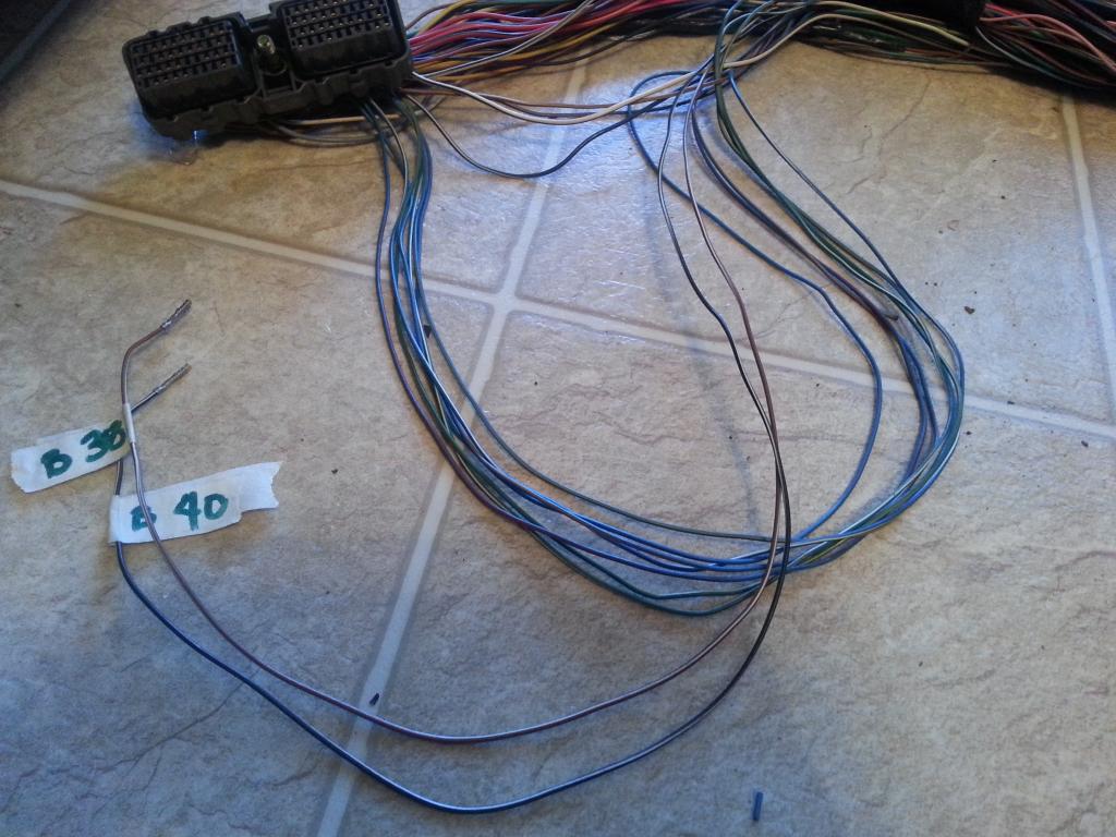
All those wires that can be extended on the part of the harness which would not go inside the firewall will be far from the 80 pin and Aristo plugs

After having extended them , I usually pull them nearer the plugs like this ...
It gives me a visual of how many wires I have done and an idea how much more to be done .. OOOOPS ..still a lot since we only have done a few .
Let me give a sample of verifying continuity from one end of a connector to the other end of the connector to check your solder points on the extensions. .
Remember those pins 52 to 58 on the 80 pin connector whose wires we just extended and where they should end in terms of continuity ?
Do you still recall these ?
Pin 1 of the 12 pin Igniter Connector goes to pin 57 of the 80 pin ECU connector
Pin 2 of the 12 pin Igniter Connector goes to pin 56 of the 80 pin ECU connector
Pin 3 of the 12 pin Igniter Connector goes to pin 55 of the 80 pin ECU connector
Pin 9 of the 12 pin Igniter Connector goes to pin 54 of the 80 pin ECU connector
Pin 8 of the 12 pin Igniter Connector goes to pin 53 of the 80 pin ECU connector
Pin 7 of the 12 pin Igniter Connector goes to pin 52 of the 80 pin ECU connector
Pin 3 of the 4 pin Igniter Connector goes to pin 58 of the 80 pin ECU connector
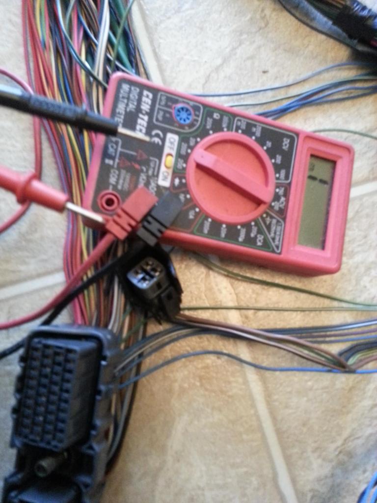
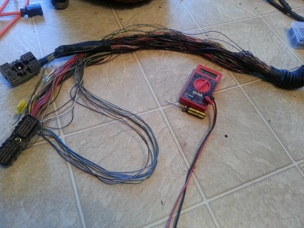
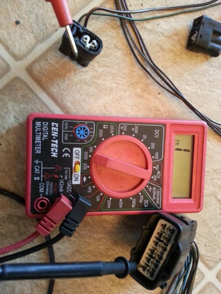
So how do you check continuity for those who are not electrically savvy ?
Get your digital multi-tester .. cheapo like what I used here doesn't matter as long as it works.
Choose a range on the ohmeter part . Initially you will have infinity denoted by 1 when those two probes are not connected together just like this
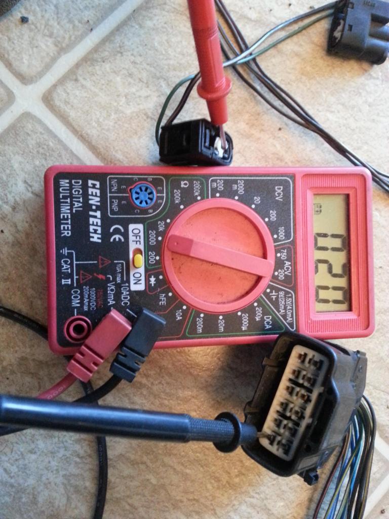
Now we start probing Pin 3 of 4 pin Igniter Connector that should be connected to pin 58 of the 80 pin ECU connector . What do you see on the multi-tester ? If you had good solder points, you should see a value on your multi-tester just like this
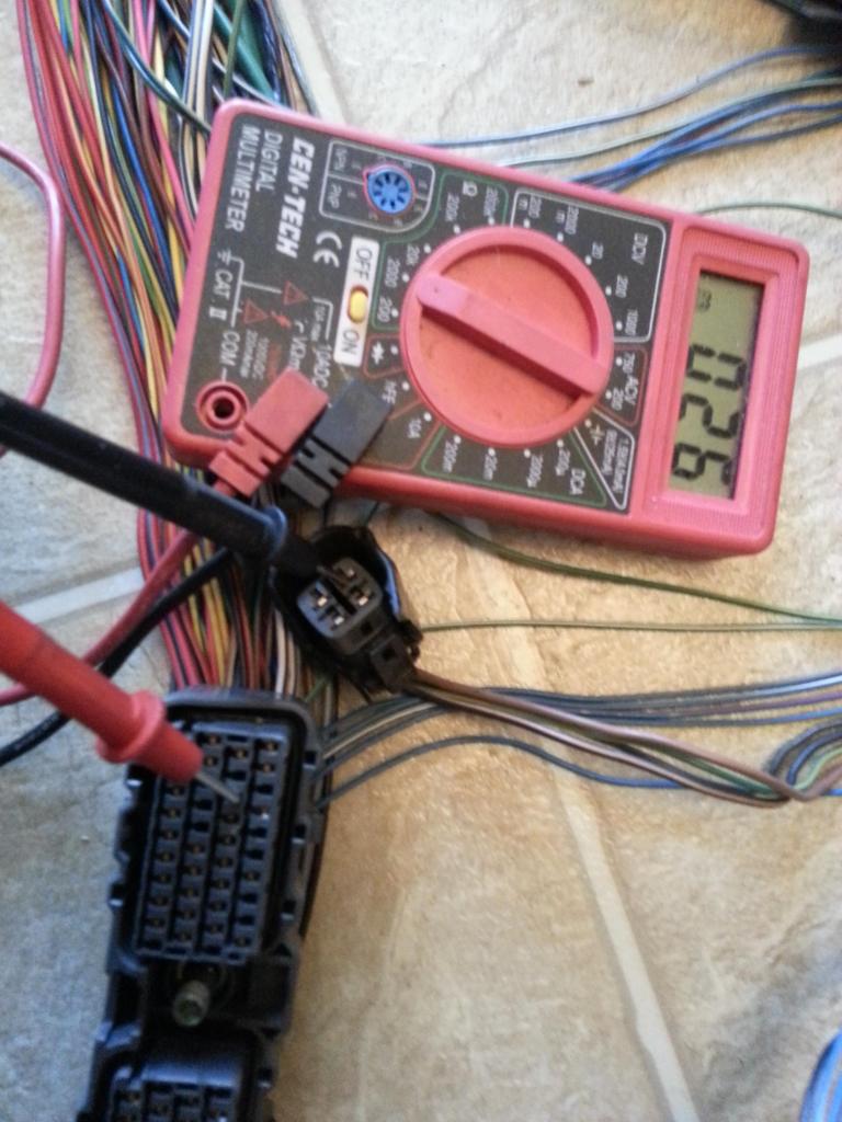
Take note that the actual number may not be the same as what you see here because there are other factors like the OHM range setting your multi-tester is in , battery of your multi-tester , etc. The most important thing is if from 1 on the left of the display which denotes infinity , you get a lower number on the right of the display then you know that there is a continuous path for current from one end to the other end . That wiring of yours is good and the solder points you did along that line were good. The number displayed actually is the resistance to current in the circuit which is measured in ohms.
ERASE ERASE , that last sentence...lol . I don't want people who are not technical enough to be discouraged and prevent them from working on the harness , you didn't have to know that to be successful in doing a harness.
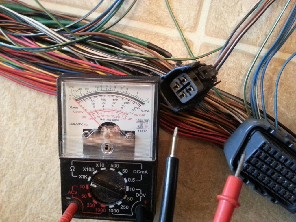
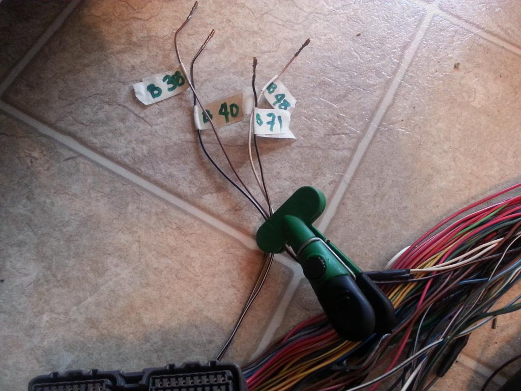
Many times just to check whether there is a continuous path from one end to the other end , I prefer using a continuity probes where in an light comes on if there is a good connection from one end to the other. You can also use an analog multi-tester / ohmeter , the moment you see that freaking arm goes from left to right , you know there is continuity .
just like this pictured below
from no continuity (tester pointer / arm on the left )
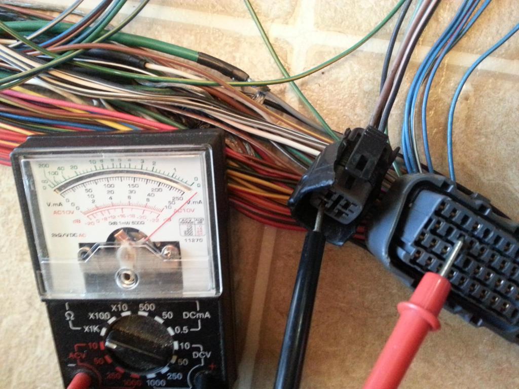
now the tester pointer / arm is on the right which means the wire in between pin 58 of the 80 pin ECU Connector and pin 3 of the 4 pin Igniter Connector is GOOD, that includes your two solder points on that line since you extended it . If let's say you don't get a good continuity in one of them , one thing you need to check is your solder points. One of them might have been disconnected or there is a cut on the wire from one end to the other end , thus you need to repair it by soldering it where you find the cut portion.
Now , I will assume you have done this to every wire we have gone through so far. If not then you didn't do THE DRILL on the 4 connectors which I have asked you to do ... go back and do it . I am about to show you how I do the CHART but it won't make any sense if you haven't done what you should have done already.
After having extended them , I usually pull them nearer the plugs like this ...

It gives me a visual of how many wires I have done and an idea how much more to be done .. OOOOPS ..still a lot
since we only have done a few . Let me give a sample of verifying continuity from one end of a connector to the other end of the connector to check your solder points on the extensions. .
Remember those pins 52 to 58 on the 80 pin connector whose wires we just extended and where they should end in terms of continuity ?

Do you still recall these ?
Pin 1 of the 12 pin Igniter Connector goes to pin 57 of the 80 pin ECU connector
Pin 2 of the 12 pin Igniter Connector goes to pin 56 of the 80 pin ECU connector
Pin 3 of the 12 pin Igniter Connector goes to pin 55 of the 80 pin ECU connector
Pin 9 of the 12 pin Igniter Connector goes to pin 54 of the 80 pin ECU connector
Pin 8 of the 12 pin Igniter Connector goes to pin 53 of the 80 pin ECU connector
Pin 7 of the 12 pin Igniter Connector goes to pin 52 of the 80 pin ECU connector
Pin 3 of the 4 pin Igniter Connector goes to pin 58 of the 80 pin ECU connector
So how do you check continuity for those who are not electrically savvy ?
Get your digital multi-tester .. cheapo like what I used here doesn't matter as long as it works.
Choose a range on the ohmeter part . Initially you will have infinity denoted by 1 when those two probes are not connected together just like this

Now we start probing Pin 3 of 4 pin Igniter Connector that should be connected to pin 58 of the 80 pin ECU connector . What do you see on the multi-tester ? If you had good solder points, you should see a value on your multi-tester just like this

Take note that the actual number may not be the same as what you see here because there are other factors like the OHM range setting your multi-tester is in , battery of your multi-tester , etc. The most important thing is if from 1 on the left of the display which denotes infinity , you get a lower number on the right of the display then you know that there is a continuous path for current from one end to the other end . That wiring of yours is good and the solder points you did along that line were good. The number displayed actually is the resistance to current in the circuit which is measured in ohms.
ERASE ERASE , that last sentence...lol . I don't want people who are not technical enough to be discouraged and prevent them from working on the harness , you didn't have to know that to be successful in doing a harness.
Many times just to check whether there is a continuous path from one end to the other end , I prefer using a continuity probes where in an light comes on if there is a good connection from one end to the other. You can also use an analog multi-tester / ohmeter , the moment you see that freaking arm goes from left to right , you know there is continuity .
just like this pictured below
from no continuity (tester pointer / arm on the left )

now the tester pointer / arm is on the right which means the wire in between pin 58 of the 80 pin ECU Connector and pin 3 of the 4 pin Igniter Connector is GOOD, that includes your two solder points on that line since you extended it . If let's say you don't get a good continuity in one of them , one thing you need to check is your solder points. One of them might have been disconnected or there is a cut on the wire from one end to the other end , thus you need to repair it by soldering it where you find the cut portion.
Now , I will assume you have done this to every wire we have gone through so far. If not then you didn't do THE DRILL on the 4 connectors which I have asked you to do ... go back and do it . I am about to show you how I do the CHART but it won't make any sense if you haven't done what you should have done already.

Last edited by gerrb; 01-31-14 at 02:05 PM.
01-31-14, 02:00 PM
#20
As I mentioned , I usually do a chart just to know what pins I have worked on and verified . You don't have to do this  but can be of help later on. Usually when I am all done with the harness and is all fully wrapped , I do a second check of the harness for quality control . Having this as reference , I have a quick guide which pin of a connector goes to which pin of another connector. I don't have to go through all those wiring diagrams again .
Something like this shown below ....... . I am not going to write all the pin numbers here since they are empty. Fill up the chart as they are done . It gives you a good , quick view of where a pin goes and a good summary of what had been done and checked on each connector of the harness.
What does CHECKED ,mean ? It means that I have finished working on it , checked continuity and have nothing more to do with it.
80 PIN ECU CONNECTOR
1
2
10
20
30
40
48 <--> Pin 3 of the Oxygen Sensor CHECKED
50
51
52 <--> Pin 7 of the 12 pin Igniter Connector CHECKED
53 <--> Pin 8 of the 12 pin igniter Connector CHECKED
54 <--> Pin 9 of the 12 pin igniter Connector CHECKED
55 <--> Pin 3 of the 12 pin igniter Connector CHECKED
56 <--> Pin 2 of the 12 pin Igniter Connector CHECKED
57 <--> Pin 1 of the 12 pin Igniter Connector CHECKED
58 <--> Pin 3 of the 4 pin Igniter Connector CHECKED
59
60
70
71 <--> Pin 1 of the Oxygen Sensor CHECKED
80
4 PIN IGNITER CONNECTOR
1 <--> Pin 12 of Plug F of Aristo plug <--> ( Pin 19 of the Data Link Connector & to ( SC3 IK1-8 , SC4 IK1-8 , MK4 ))
2 <--> Pin 6 of Plug F of Aristo plug <--> Pin 1 of the Noise Filter <--> ( SC3 IJ1-7 , SC4 EB2-2 , MK4 IJ1-1 or IJ1-9 )
3 <--> Pin 58 of the 80 pin ECU connector CHECKED
4 <--> Ground Connector on the Front Side of Intake Manifold <--> Pin 2 of the Noise filter Connector CHECKED
12 PIN IGNITER CONNECTOR
1 <--> Pin 57 of the 80 pin ECU connector CHECKED
2 <--> Pin 56 of the 80 pin ECU connector CHECKED
3 <--> Pin 55 of the 80 pin ECU connector CHECKED
4 <--> Pin 2 of the Ignition Coil Connector 3 CHECKED
5 <--> Pin 2 of the Ignition Coil Connector 2 CHECKED
6 <--> Pin 2 of the Ignition Coil Connector 1 CHECKED
7 <--> Pin 52 of the 80 pin ECU connector CHECKED
8 <--> Pin 53 of the 80 pin ECU connector CHECKED
9 <--> Pin 54 of the 80 pin ECU connector CHECKED
10 <--> Pin 2 of the Ignition Coil Connector 4 CHECKED
11 <--> Pin 2 of the Ignition Coil Connector 5 CHECKED
12 <--> Pin 2 of the Ignition Coil Connector 6 CHECKED
IGNITION COIL 1
1
2 <--> Pin 6 of the 12 Pin Igniter Connector CHECKED
IGNITION COIL 2
1
2 <--> Pin 5 of the 12 Pin Igniter Connector CHECKED
IGNITION COIL 3
1
2 <--> Pin 4 of the 12 Pin Igniter Connector CHECKED
IGNITION COIL 4
1
2 <--> Pin 10 of the 12 Pin Igniter Connector CHECKED
IGNITION COIL 5
1
2 <--> Pin 11 of the 12 Pin Igniter Connector CHECKED
IGNITION COIL 6
1
2 <--> Pin 12 of the 12 Pin Igniter Connector CHECKED
NOISE FILTER
1 <--> Pin 2 of the 4 pin Igniter Connector <--> ( SC3 IJ1-7, SC4 EB2-2 , MK4 IJ1-1 or IJ1-9 )
2 <--> Ground Connector on the Front Side of Intake Manifold <--> Pin 4 of the 4 pin Igniter Connector CHECKED
The following plugs are necessary only if you are going stock 2jzgte setup
Oxygen Sensor O2
1 <--> Pin 71 of the 80 pin ECU Connector CHECKED
2 <--> Pin 3 of Plug E of Aristo Plug <-> ( Pin 12 of the Data Link Connector <--> ( SC3 IJ1-12 & EB2-1 & Short-4 , SC4 IJ1-12 & EB2-3 , MK4 EA3-3 ))
3 <--> Pin 48 of the 80 pin ECU Connector CHECKED
The following plugs needs to be taken out
BIG GRAY ARISTO PLUG
PLUG E
3 <--> Pin 2 of Oxygen Sensor <--> (Pin 12 of the Data Link Connector <--> ( SC3 IJ1-12 & EB2-1 & Short-4 , SC4 IJ1-12 & EB2-3 , MK4 EA3-3 ))
PLUG F
6 <--> Pin 1 of the Noise Filter <--> ( SC3 IJ1-7 , SC4 EB2-2 , MK4 IJ1-1 or IJ1-9 )
12 <--> ( Pin 19 of the Data Link Connector & to ( SC3 IK1-8 , SC4 IK1-8 , MK4 ))
but can be of help later on. Usually when I am all done with the harness and is all fully wrapped , I do a second check of the harness for quality control . Having this as reference , I have a quick guide which pin of a connector goes to which pin of another connector. I don't have to go through all those wiring diagrams again . Something like this shown below ....... . I am not going to write all the pin numbers here since they are empty. Fill up the chart as they are done . It gives you a good , quick view of where a pin goes and a good summary of what had been done and checked on each connector of the harness.
What does CHECKED ,mean ? It means that I have finished working on it , checked continuity and have nothing more to do with it.
80 PIN ECU CONNECTOR
1
2
10
20
30
40
48 <--> Pin 3 of the Oxygen Sensor CHECKED
50
51
52 <--> Pin 7 of the 12 pin Igniter Connector CHECKED
53 <--> Pin 8 of the 12 pin igniter Connector CHECKED
54 <--> Pin 9 of the 12 pin igniter Connector CHECKED
55 <--> Pin 3 of the 12 pin igniter Connector CHECKED
56 <--> Pin 2 of the 12 pin Igniter Connector CHECKED
57 <--> Pin 1 of the 12 pin Igniter Connector CHECKED
58 <--> Pin 3 of the 4 pin Igniter Connector CHECKED
59
60
70
71 <--> Pin 1 of the Oxygen Sensor CHECKED
80
4 PIN IGNITER CONNECTOR
1 <--> Pin 12 of Plug F of Aristo plug <--> ( Pin 19 of the Data Link Connector & to ( SC3 IK1-8 , SC4 IK1-8 , MK4 ))
2 <--> Pin 6 of Plug F of Aristo plug <--> Pin 1 of the Noise Filter <--> ( SC3 IJ1-7 , SC4 EB2-2 , MK4 IJ1-1 or IJ1-9 )
3 <--> Pin 58 of the 80 pin ECU connector CHECKED
4 <--> Ground Connector on the Front Side of Intake Manifold <--> Pin 2 of the Noise filter Connector CHECKED
12 PIN IGNITER CONNECTOR
1 <--> Pin 57 of the 80 pin ECU connector CHECKED
2 <--> Pin 56 of the 80 pin ECU connector CHECKED
3 <--> Pin 55 of the 80 pin ECU connector CHECKED
4 <--> Pin 2 of the Ignition Coil Connector 3 CHECKED
5 <--> Pin 2 of the Ignition Coil Connector 2 CHECKED
6 <--> Pin 2 of the Ignition Coil Connector 1 CHECKED
7 <--> Pin 52 of the 80 pin ECU connector CHECKED
8 <--> Pin 53 of the 80 pin ECU connector CHECKED
9 <--> Pin 54 of the 80 pin ECU connector CHECKED
10 <--> Pin 2 of the Ignition Coil Connector 4 CHECKED
11 <--> Pin 2 of the Ignition Coil Connector 5 CHECKED
12 <--> Pin 2 of the Ignition Coil Connector 6 CHECKED
IGNITION COIL 1
1
2 <--> Pin 6 of the 12 Pin Igniter Connector CHECKED
IGNITION COIL 2
1
2 <--> Pin 5 of the 12 Pin Igniter Connector CHECKED
IGNITION COIL 3
1
2 <--> Pin 4 of the 12 Pin Igniter Connector CHECKED
IGNITION COIL 4
1
2 <--> Pin 10 of the 12 Pin Igniter Connector CHECKED
IGNITION COIL 5
1
2 <--> Pin 11 of the 12 Pin Igniter Connector CHECKED
IGNITION COIL 6
1
2 <--> Pin 12 of the 12 Pin Igniter Connector CHECKED
NOISE FILTER
1 <--> Pin 2 of the 4 pin Igniter Connector <--> ( SC3 IJ1-7, SC4 EB2-2 , MK4 IJ1-1 or IJ1-9 )
2 <--> Ground Connector on the Front Side of Intake Manifold <--> Pin 4 of the 4 pin Igniter Connector CHECKED
The following plugs are necessary only if you are going stock 2jzgte setup
Oxygen Sensor O2
1 <--> Pin 71 of the 80 pin ECU Connector CHECKED
2 <--> Pin 3 of Plug E of Aristo Plug <-> ( Pin 12 of the Data Link Connector <--> ( SC3 IJ1-12 & EB2-1 & Short-4 , SC4 IJ1-12 & EB2-3 , MK4 EA3-3 ))
3 <--> Pin 48 of the 80 pin ECU Connector CHECKED
The following plugs needs to be taken out
BIG GRAY ARISTO PLUG
PLUG E
3 <--> Pin 2 of Oxygen Sensor <--> (Pin 12 of the Data Link Connector <--> ( SC3 IJ1-12 & EB2-1 & Short-4 , SC4 IJ1-12 & EB2-3 , MK4 EA3-3 ))
PLUG F
6 <--> Pin 1 of the Noise Filter <--> ( SC3 IJ1-7 , SC4 EB2-2 , MK4 IJ1-1 or IJ1-9 )
12 <--> ( Pin 19 of the Data Link Connector & to ( SC3 IK1-8 , SC4 IK1-8 , MK4 ))
Last edited by gerrb; 01-31-14 at 02:07 PM.
01-31-14, 02:04 PM
#21
Let me give you the tools to check whether what we are doing is right . I want you to verify for yourself that I just didn't pick up the pin numbers of plugs randomly and where they should go.
I will post wiring diagrams so you can verify the Pin Numbers we wrote on the INFO section of plugs we worked on and have the chance to trace the wiring . If you cannot read wiring diagrams , DO NOT WORRY ABOUT THEM. YOU DO NOT NEED TO LEARN HOW TO READ THEM. It won't stop you from doing the 2jzgte harness because I have written down basically everything you needed. These diagrams are just cross references for those who wants to verify what I have written so far.
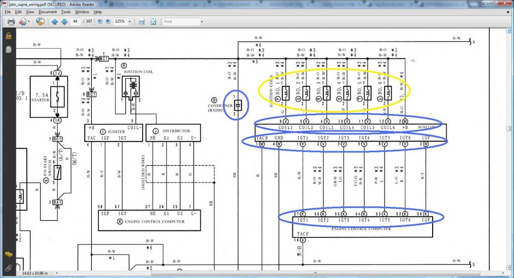
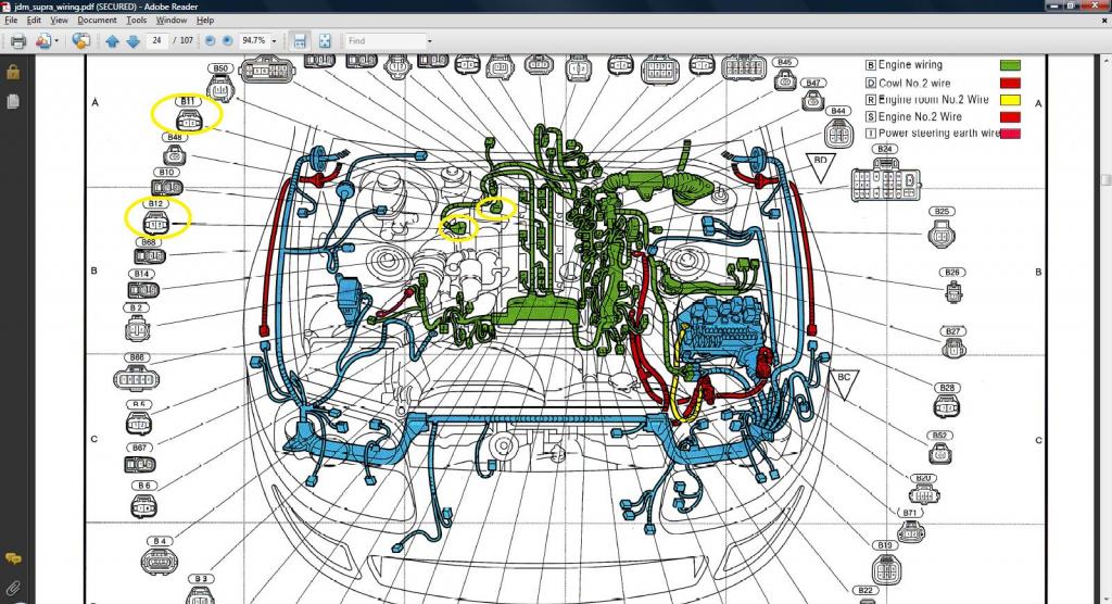
I will post diagrams related only to the plugs we are currently working on. So as not to be distracted with the other components on the diagram , I enclosed the components / connectors we are working on with a BLUE ELLIPSIS . Just look at those components . You will have the pin numbers written , same ones I wrote on the INFO of plugs. If the pin numbers are too small for you and can't be seen , you either use the magnifier on your computer or print the photo .
DIAGRAMS TO VERIFY PIN NUMBERING & WHERE THE WIRE GOES
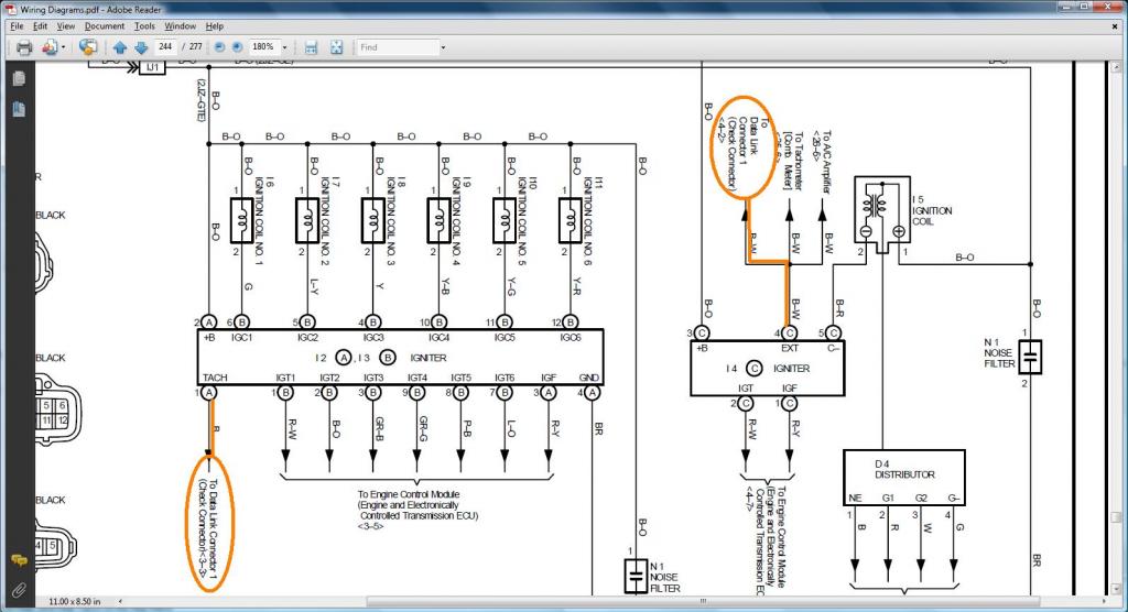
*** Noise Filter / 4 Pin & 12 Pin Igniter Connectors ***
IF you observe the igniter , anything that is labeled V belongs to the 12 pin Igniter Connector and anything labeled W belongs to the 4 pin Igniter Connector
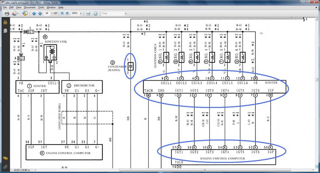
From the diagram above , you don't see were Pin 2 of the Noise Filter and Pin 4 of the 4 pin Igniter Connector goes to ... reducing the size of diagram helps now.
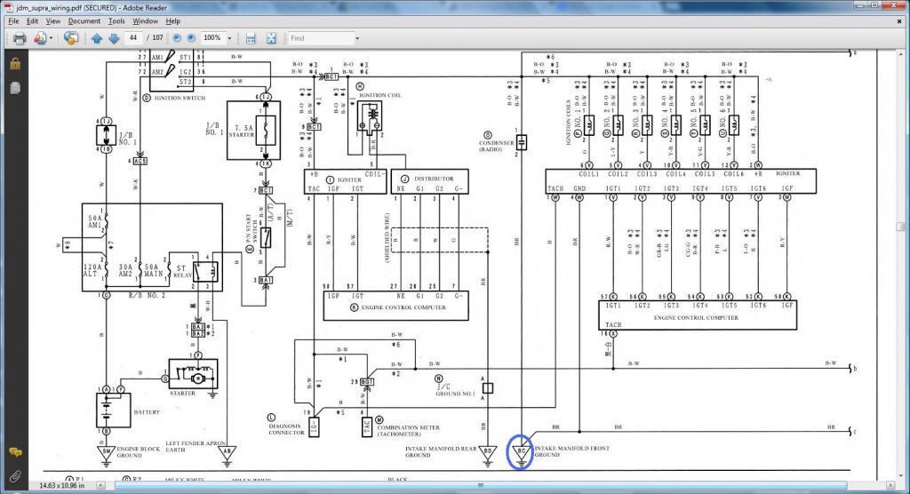
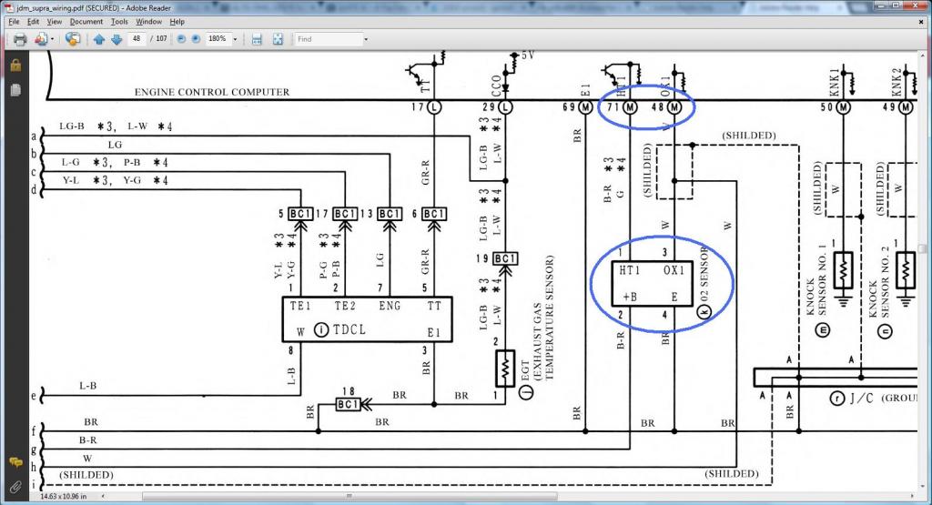
What we have on the diagram below is a 4 pin oxygen sensor . Don't worry about it . Just verify pins 1 to 3. In a 4 pin oxygen sensor , usually two are ground or what they call common , one for the heater ground and one for the signal ground so in effect it can be just one wire. The pin 4 is just a ground which goes to Pin 3 (E1) of the diagnostic port and the Ground on the Rear Side of the Intake Manifold . That is the reason you can get away with 3 wire oxygen sensors.
The following diagrams maybe confusing to many. If they are, don't even bother with them. YOU DO NOT NEED THEM . It's for those who can analyze wiring diagrams. Just showing you how the PROs do it. It is actually reading the functionality of a pin (what it is for) on the 2jzgte harness then looking for that wire on your car for the same functionality so you know where to connect a particular wire. This is the hardwork that's why you pay high dollar for a harness. That hardwork has been done for you already in our 2jzgte harness build.
DIAGRAMS TO VERIFY WHERE A WIRE SHOULD GO IN A SC300, SC400, MKIV
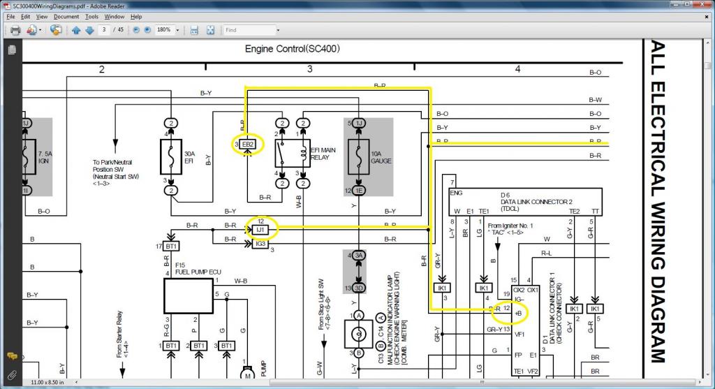
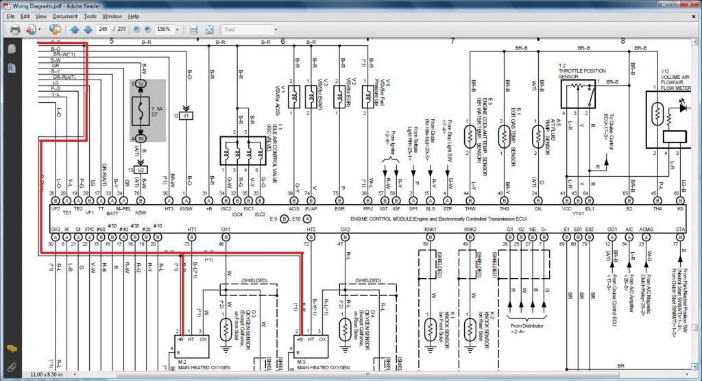
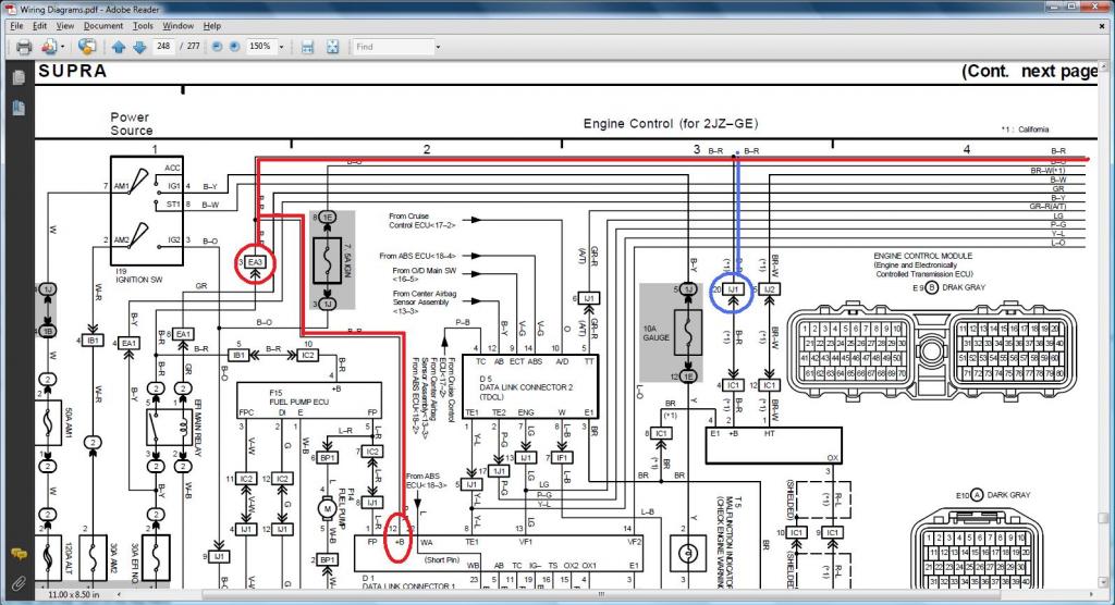
Do you remember these notations I have written in parenthesis and bold characters like ( should go to Pin 19 of the Data Link Connector & to ( SC3 IK1-8 , SC4 IK1-8 , MK4 )) ? How do you know what plug and pin the wire should go on the SC300 , SC400 or MKIV ? By reading the wiring diagrams of those particular cars.
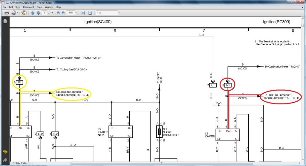
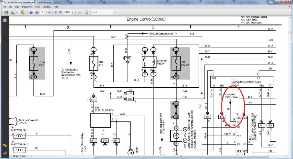
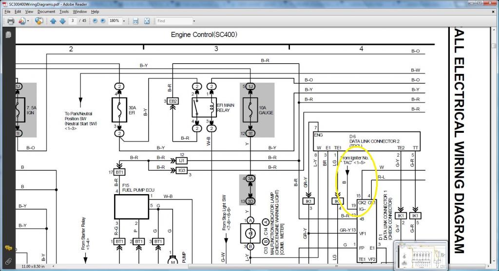
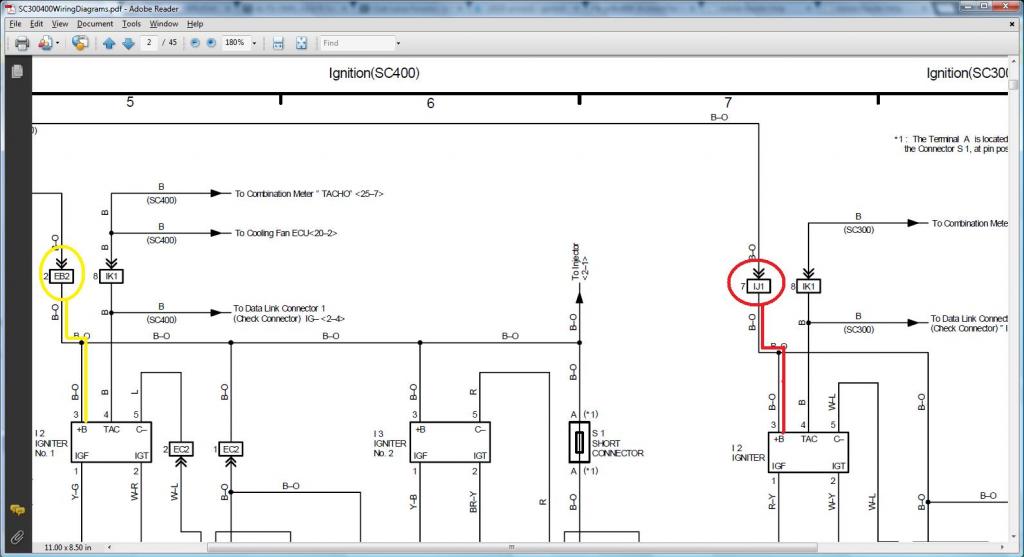
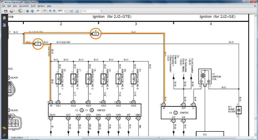
Pin 1 of the 4 pin Igniter Connector which you took out of Pin 12 of Plug F of the big gray Aristo plug ( should go to Pin 19 of the Data Link Connector & to ( SC3 IK1-8 , SC4 IK1-8 , MK4 )) . This pin, looking at the 2jzgte REFERENCE INFO is for the TACH . So looking at my SC300 diagram , it tells me that this TACH pin goes to pin 8 of connector IK1 (encircled in red on the diagram) and to the Data Link Connector. On the SC400 diagram , it tells me that the TACH pin goes also to pin 8 of connector IK1 (encircled in yellow on the diagram ) and to the Data Link Connector . On my MKIV , it tells me that it goes to the Data Link Connector / Tachometer. THUS the 2jzgte Pin 1 of the 4 pin Igniter Connector goes to SC3 IK1-8 or SC4 IK1-8 AND goes to Pin 19 of the Data Link Connector for the SC300 , SC400 and MKIV.
SC300 IK1-8 / SC400 IK1-8
MKIV
If I further follow the diagram link above to the Data Link Connector for the SC300 , SC400 and MKIV , it will show me that indeed that same Pin 1 of the Igniter Connector goes to Pin 19 of the Data Link Connector
SC300
SC400
MKIV
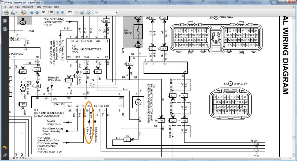
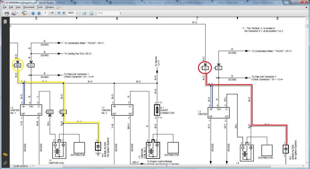
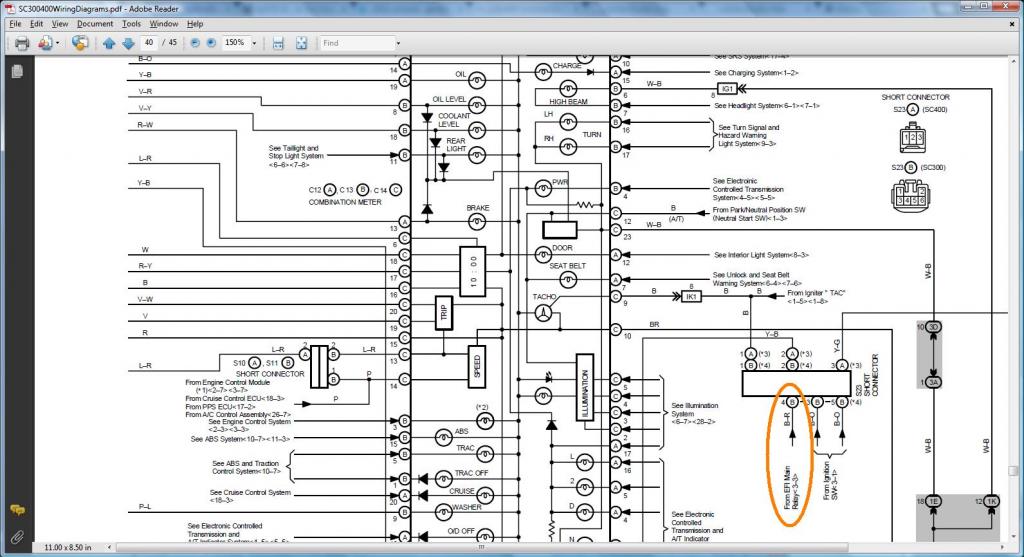
Pin 2 of the 4 pin Igniter Connector which you took out of Pin 6 of Plug F of the big gray Aristo plug ( should go to ( SC3 IJ1-7 , SC4 EB2-2 , MK4 IJ1-1 or IJ1-9 )) . This pin, looking at the 2jzgte REFERENCE INFO is for the B+ (voltage) source. On the SC300 , the B+ pin goes to Pin 7 of connector IJ1 . On the SC400 it goes to Pin 2 of connector EB2 . And on the MKIV it goes to Pin 1 or 9 of connector IJ1 for the MK4. Again check what is encircled in yellow for the SC400 , in red for the SC300 and in orange for the MKIV.
SC300 / SC400
MKIV
Pin 1 of the Noise Filter Connector ( should go to ( SC3 IJ1-7, SC4 EB2-2 , MK4 IJ1-1 or IJ1-9 )) . This pin which is connected to Pin 2 of the 4 pin Igniter Connector would consequently go to the same places were Pin 2 did . That means , on the SC300 , it goes to Pin 7 of connector IJ1 , goes to Pin 2 of connector EB2 for the SC400 and Pin 1 or 9 of connector IJ1 for the MK4. Again check what is encircled in yellow for the SC400 , in red for the SC300 and in orange for the MKIV.
SC300 IJ1-7 / SC400 EB-2 also you see in blue where Pin 1 of the Noise Filter intersect with Pin 2 of the 4 pin Igniter Connector
MKIV IJ1-1 or IK1-9 also you see in blue where Pin 1 of the Noise Filter intersect with Pin 2 of the 4 pin Igniter Connector
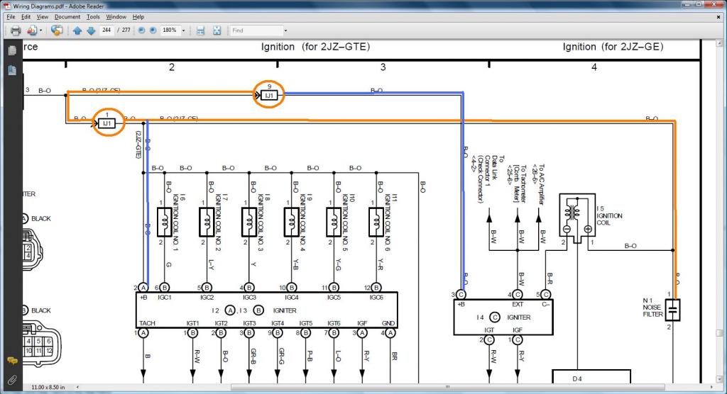
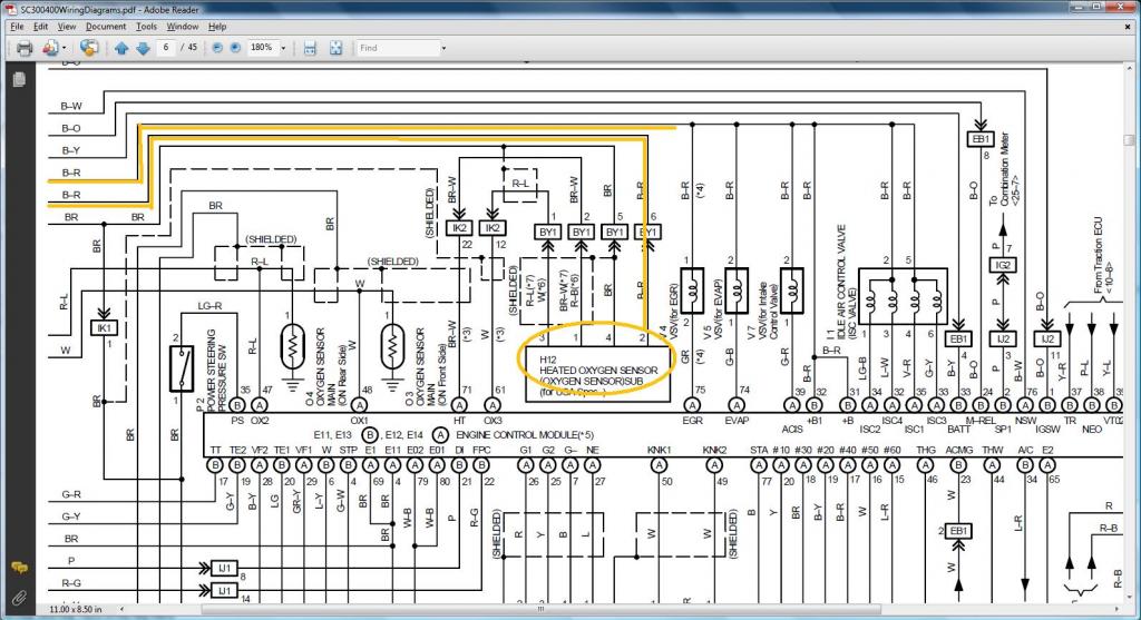
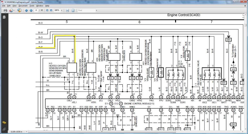
Pin 2 of the Oxygen Sensor which you took out of Pin 3 of Plug E of Aristo Plug ( should go to Pin 12 of the Data Link Connector & to ( SC3 IJ1-12 & EB2-1 & Short-4 , SC4 IJ1-12 & EB2-3 , MK4 EA3-3 )). Pin 2 of the 2jzgte harness (if you are keeping the oxygen sensor) is the B+ supply for the oxygen sensor. For the SC300 , that wire is connected to Pin 12 of the Data Link Connector and to Pin 12 of Connector IJ1 and to Pin 1 of Connector EB2 and to Pin 4 of the Short Connector . For the SC400 , that wire is connected to Pin 12 of the Data Link Connector and to Pin 12 of Connector IJ1 and to Pin 3 of Connector EB2. For the MKIV , that wire is connected to Pin 12 of the Data Link Connector and to Pin 3 of Connector EA3.
SC300 (read the first picture below to be on the right side of the second picture so you see the continous flow of that orange line)
 \
\
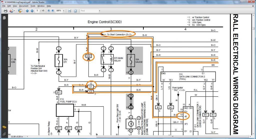
If I further follow the wiring diagram where the SHORT CONNECTOR is it will show me that the same Pin goes to pin 4 of the SHORT CONNECTOR
SC400 (read the first picture below to be on the right side of the second picture so you see the continous flow of that yellow line)
MKIV (read the first picture below to be on the right side of the second picture so you see the continous flow of that red line). Take note that on a USDM MKIV , there are more than one oxygen sensors. On a California edition , even more . That is why you see three on the following diagram.
I have shown you how to deduce and find out where a 2jzgte harness wire should go in a SC300 , SC400 , MKIV body plug. Just check its functionality from the 2jzgte REFERENCE INFO and deduce from your particular car's wiring diagram where it should go. I couldn't possibly show you something like this for all the wires that go to a body plug. I would never finish this write up. But I hope you are able to assimilate the process of doing it. That is what you pay big bucks for . The skill and time they put into the work. That hard work , you don't have to do if you follow well this harness build thread.
I will post wiring diagrams so you can verify the Pin Numbers we wrote on the INFO section of plugs we worked on and have the chance to trace the wiring . If you cannot read wiring diagrams , DO NOT WORRY ABOUT THEM. YOU DO NOT NEED TO LEARN HOW TO READ THEM. It won't stop you from doing the 2jzgte harness because I have written down basically everything you needed. These diagrams are just cross references for those who wants to verify what I have written so far.
I will post diagrams related only to the plugs we are currently working on. So as not to be distracted with the other components on the diagram , I enclosed the components / connectors we are working on with a BLUE ELLIPSIS . Just look at those components . You will have the pin numbers written , same ones I wrote on the INFO of plugs. If the pin numbers are too small for you and can't be seen , you either use the magnifier on your computer or print the photo .
DIAGRAMS TO VERIFY PIN NUMBERING & WHERE THE WIRE GOES
*** Noise Filter / 4 Pin & 12 Pin Igniter Connectors ***
IF you observe the igniter , anything that is labeled V belongs to the 12 pin Igniter Connector and anything labeled W belongs to the 4 pin Igniter Connector

From the diagram above , you don't see were Pin 2 of the Noise Filter and Pin 4 of the 4 pin Igniter Connector goes to ... reducing the size of diagram helps now.

What we have on the diagram below is a 4 pin oxygen sensor . Don't worry about it . Just verify pins 1 to 3. In a 4 pin oxygen sensor , usually two are ground or what they call common , one for the heater ground and one for the signal ground so in effect it can be just one wire. The pin 4 is just a ground which goes to Pin 3 (E1) of the diagnostic port and the Ground on the Rear Side of the Intake Manifold . That is the reason you can get away with 3 wire oxygen sensors.

The following diagrams maybe confusing to many. If they are, don't even bother with them. YOU DO NOT NEED THEM . It's for those who can analyze wiring diagrams. Just showing you how the PROs do it. It is actually reading the functionality of a pin (what it is for) on the 2jzgte harness then looking for that wire on your car for the same functionality so you know where to connect a particular wire. This is the hardwork that's why you pay high dollar for a harness. That hardwork has been done for you already in our 2jzgte harness build.
DIAGRAMS TO VERIFY WHERE A WIRE SHOULD GO IN A SC300, SC400, MKIV
Do you remember these notations I have written in parenthesis and bold characters like ( should go to Pin 19 of the Data Link Connector & to ( SC3 IK1-8 , SC4 IK1-8 , MK4 )) ? How do you know what plug and pin the wire should go on the SC300 , SC400 or MKIV ? By reading the wiring diagrams of those particular cars.
Pin 1 of the 4 pin Igniter Connector which you took out of Pin 12 of Plug F of the big gray Aristo plug ( should go to Pin 19 of the Data Link Connector & to ( SC3 IK1-8 , SC4 IK1-8 , MK4 )) . This pin, looking at the 2jzgte REFERENCE INFO is for the TACH . So looking at my SC300 diagram , it tells me that this TACH pin goes to pin 8 of connector IK1 (encircled in red on the diagram) and to the Data Link Connector. On the SC400 diagram , it tells me that the TACH pin goes also to pin 8 of connector IK1 (encircled in yellow on the diagram ) and to the Data Link Connector . On my MKIV , it tells me that it goes to the Data Link Connector / Tachometer. THUS the 2jzgte Pin 1 of the 4 pin Igniter Connector goes to SC3 IK1-8 or SC4 IK1-8 AND goes to Pin 19 of the Data Link Connector for the SC300 , SC400 and MKIV.
SC300 IK1-8 / SC400 IK1-8

MKIV

If I further follow the diagram link above to the Data Link Connector for the SC300 , SC400 and MKIV , it will show me that indeed that same Pin 1 of the Igniter Connector goes to Pin 19 of the Data Link Connector
SC300

SC400

MKIV

Pin 2 of the 4 pin Igniter Connector which you took out of Pin 6 of Plug F of the big gray Aristo plug ( should go to ( SC3 IJ1-7 , SC4 EB2-2 , MK4 IJ1-1 or IJ1-9 )) . This pin, looking at the 2jzgte REFERENCE INFO is for the B+ (voltage) source. On the SC300 , the B+ pin goes to Pin 7 of connector IJ1 . On the SC400 it goes to Pin 2 of connector EB2 . And on the MKIV it goes to Pin 1 or 9 of connector IJ1 for the MK4. Again check what is encircled in yellow for the SC400 , in red for the SC300 and in orange for the MKIV.
SC300 / SC400

MKIV

Pin 1 of the Noise Filter Connector ( should go to ( SC3 IJ1-7, SC4 EB2-2 , MK4 IJ1-1 or IJ1-9 )) . This pin which is connected to Pin 2 of the 4 pin Igniter Connector would consequently go to the same places were Pin 2 did . That means , on the SC300 , it goes to Pin 7 of connector IJ1 , goes to Pin 2 of connector EB2 for the SC400 and Pin 1 or 9 of connector IJ1 for the MK4. Again check what is encircled in yellow for the SC400 , in red for the SC300 and in orange for the MKIV.
SC300 IJ1-7 / SC400 EB-2 also you see in blue where Pin 1 of the Noise Filter intersect with Pin 2 of the 4 pin Igniter Connector

MKIV IJ1-1 or IK1-9 also you see in blue where Pin 1 of the Noise Filter intersect with Pin 2 of the 4 pin Igniter Connector

Pin 2 of the Oxygen Sensor which you took out of Pin 3 of Plug E of Aristo Plug ( should go to Pin 12 of the Data Link Connector & to ( SC3 IJ1-12 & EB2-1 & Short-4 , SC4 IJ1-12 & EB2-3 , MK4 EA3-3 )). Pin 2 of the 2jzgte harness (if you are keeping the oxygen sensor) is the B+ supply for the oxygen sensor. For the SC300 , that wire is connected to Pin 12 of the Data Link Connector and to Pin 12 of Connector IJ1 and to Pin 1 of Connector EB2 and to Pin 4 of the Short Connector . For the SC400 , that wire is connected to Pin 12 of the Data Link Connector and to Pin 12 of Connector IJ1 and to Pin 3 of Connector EB2. For the MKIV , that wire is connected to Pin 12 of the Data Link Connector and to Pin 3 of Connector EA3.
SC300 (read the first picture below to be on the right side of the second picture so you see the continous flow of that orange line)
 \
\
If I further follow the wiring diagram where the SHORT CONNECTOR is it will show me that the same Pin goes to pin 4 of the SHORT CONNECTOR

SC400 (read the first picture below to be on the right side of the second picture so you see the continous flow of that yellow line)


MKIV (read the first picture below to be on the right side of the second picture so you see the continous flow of that red line). Take note that on a USDM MKIV , there are more than one oxygen sensors. On a California edition , even more . That is why you see three on the following diagram.


I have shown you how to deduce and find out where a 2jzgte harness wire should go in a SC300 , SC400 , MKIV body plug. Just check its functionality from the 2jzgte REFERENCE INFO and deduce from your particular car's wiring diagram where it should go. I couldn't possibly show you something like this for all the wires that go to a body plug. I would never finish this write up. But I hope you are able to assimilate the process of doing it. That is what you pay big bucks for . The skill and time they put into the work. That hard work , you don't have to do if you follow well this harness build thread.
Last edited by gerrb; 01-31-14 at 02:08 PM.
01-31-14, 02:06 PM
#22
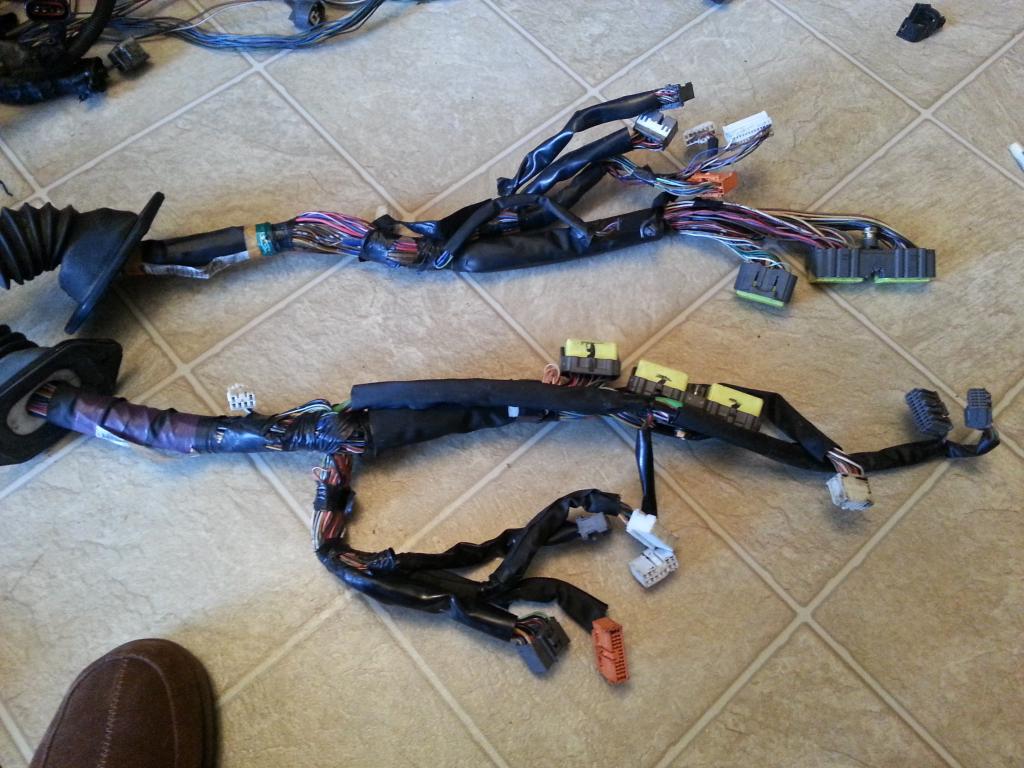
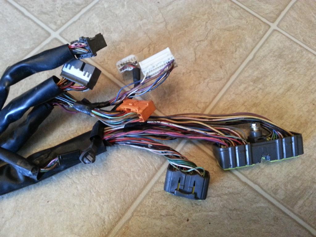
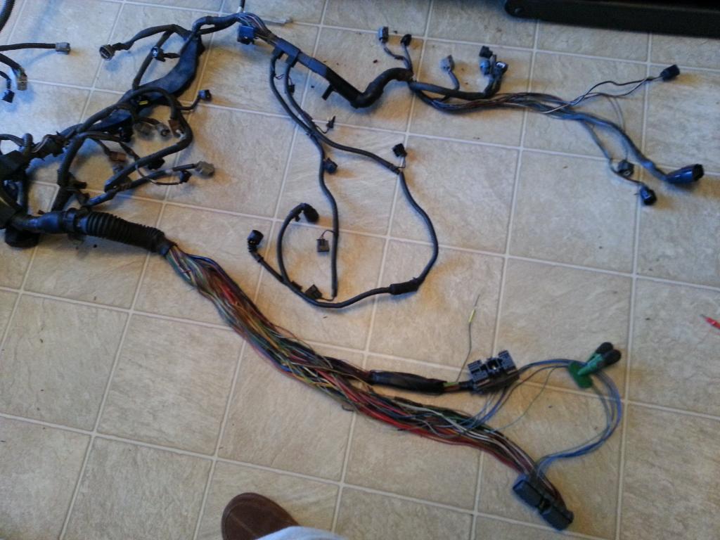
I know at this point , you are supposed to be done working on the 4 plugs we have discussed in the previous posts. Allow me to add some pictures here for what I have done on the two harnesses I was working on .
To start with on both harnesses , I had these
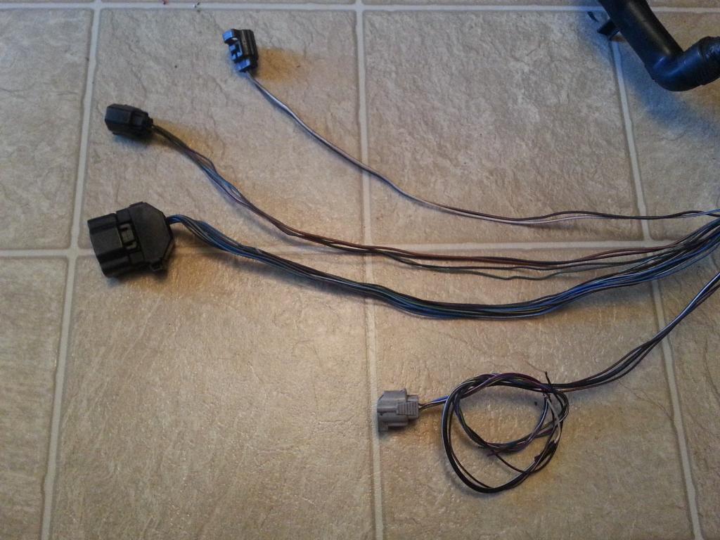
For Aaron's harness which will be on a R154 and no catalytic converter and with AEM v2 , he doesn't need the stock oxygen sensor plug. For my harness , although I would be on a stroker 3.4 engine , V160 and proEFI , I still want to keep my harness as stock as possible keeping the oxygen sensor , auto transmission wiring , etc. so I have a sample harness for this build thread and for those doing a stock 2jzgte swap with auto transmission. Having all the auto transmission plugs , that gives me the flexibility of using either my V160 6 speed or my ATF auto transmission with just minor modifications on the harness depending on which transmission I am using.
It is nice to have less wires going around the engine bay ,cleaner look. On my Red Mamba 1 , there are no wires on top of that passenger strut tower . Having built my harness from an Aristo 2jzgte harness , the Igniter and Noise Filter plugs were at the farthest point that is why you probably see my igniter down there on the left side of the picture... kind a dark when I took the picture some time ago during the RM1 build process.
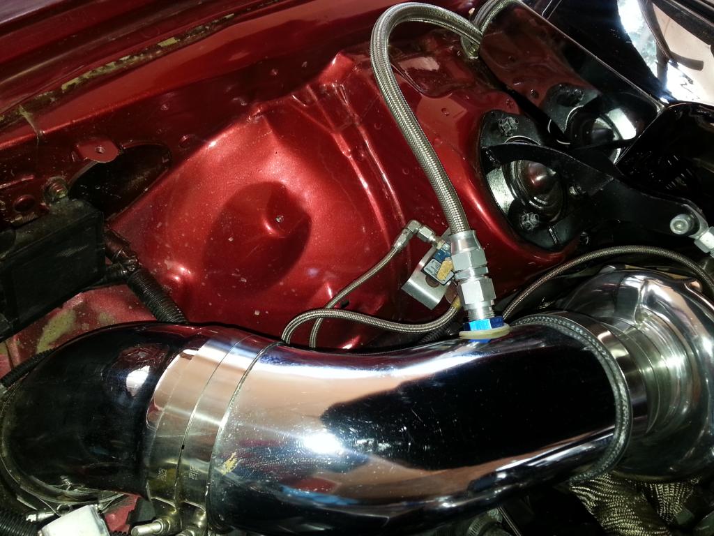
I prefer to relocate my oxygen sensor plug and wiring at the back near the firewall since that sensor will be on the downpipe. If I keep my wiring for the oxygen sensor where it is right now then those wires will have to go from front to my aftermarket down pipe thus will be an eyesore. If you are going just for a stock 2jzgte swap , leave the plug where it is , less work.
Thus , for the two harnesses , I re-used the wires that go to pin 1 & 2 of the oxygen sensor for my boost solenoid. Pin 1 goes to pin 71 of the 80 pin ECU connector. Pin 2 is already connected to a B+ voltage supply which is needed for a solenoid. Took out the pins from their plugs and labeled them accordingly so I know what they are for. I also have taken note that I will have to put my own wiring for an oxygen sensor later on once I am in that area of the harness where I wanted the plug to be.
NOTE : If you are reusing a wire for something else like a signal wire , make sure that it is a wire in which there is nothing T'ed to it along the way to the ECU connectors not unless it is really to be T'ed let us say to a B+ supply or a ground for a sensor.
Once I was done doing THE DRILL on all these plugs , I covered them with electrical tape. Since the noise filter ,4 & 12 pin igniter connectors where going to one place , I wrapped them all together . And eventually covered them with a corrugated flexible hose as you can see in one of the harness. I had to label also wires without plugs so I knew what they were for.
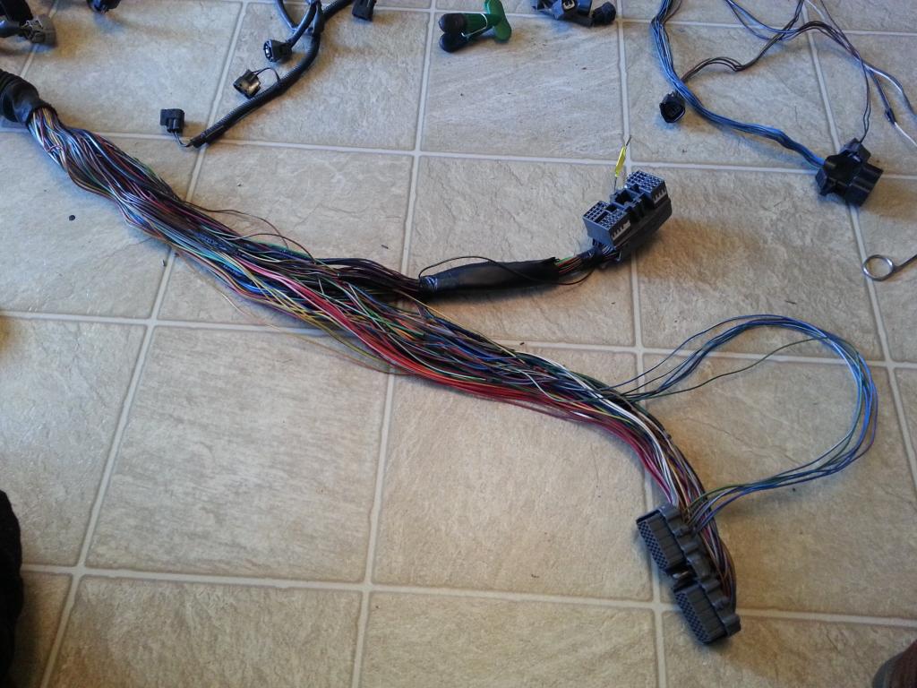
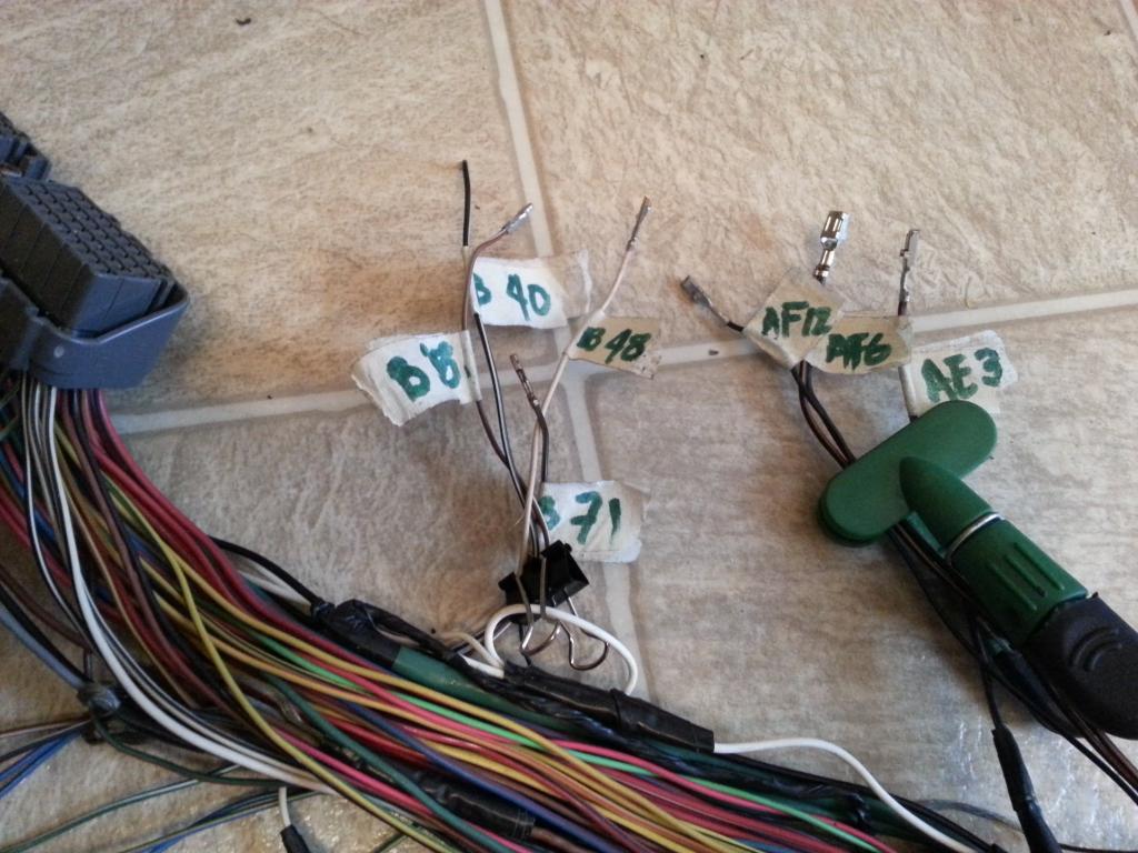
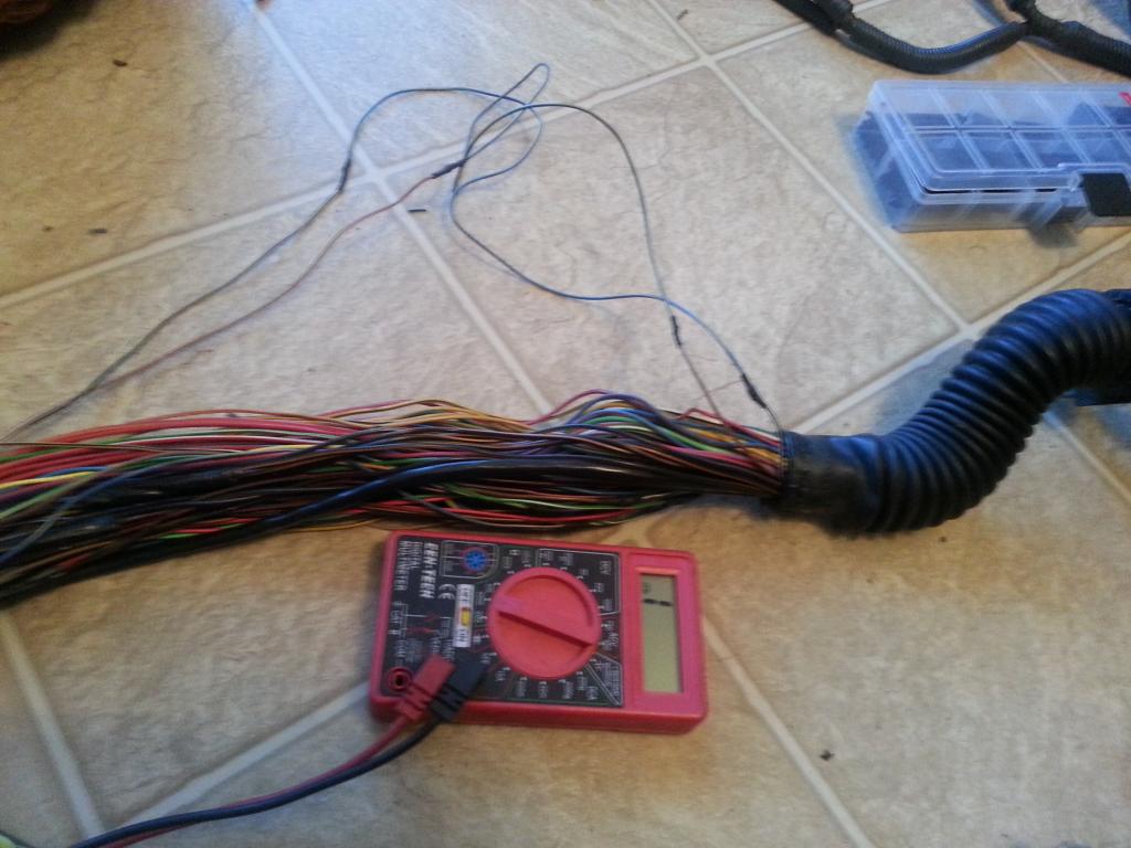
On the other end where the ECU connectors are , since there are a lot of loose ends , I make sure that all wires that are not in a connector are properly labeled . I separate wires accordingly. Like all those extra wires that are for future use are all together and all those wires that go to different body plugs are all together.
To start with on both harnesses , I had these

For Aaron's harness which will be on a R154 and no catalytic converter and with AEM v2 , he doesn't need the stock oxygen sensor plug. For my harness , although I would be on a stroker 3.4 engine , V160 and proEFI , I still want to keep my harness as stock as possible keeping the oxygen sensor , auto transmission wiring , etc. so I have a sample harness for this build thread and for those doing a stock 2jzgte swap with auto transmission. Having all the auto transmission plugs , that gives me the flexibility of using either my V160 6 speed or my ATF auto transmission with just minor modifications on the harness depending on which transmission I am using.
It is nice to have less wires going around the engine bay ,cleaner look. On my Red Mamba 1 , there are no wires on top of that passenger strut tower . Having built my harness from an Aristo 2jzgte harness , the Igniter and Noise Filter plugs were at the farthest point that is why you probably see my igniter down there on the left side of the picture... kind a dark when I took the picture some time ago during the RM1 build process.

I prefer to relocate my oxygen sensor plug and wiring at the back near the firewall since that sensor will be on the downpipe. If I keep my wiring for the oxygen sensor where it is right now then those wires will have to go from front to my aftermarket down pipe thus will be an eyesore. If you are going just for a stock 2jzgte swap , leave the plug where it is , less work.
Thus , for the two harnesses , I re-used the wires that go to pin 1 & 2 of the oxygen sensor for my boost solenoid. Pin 1 goes to pin 71 of the 80 pin ECU connector. Pin 2 is already connected to a B+ voltage supply which is needed for a solenoid. Took out the pins from their plugs and labeled them accordingly so I know what they are for. I also have taken note that I will have to put my own wiring for an oxygen sensor later on once I am in that area of the harness where I wanted the plug to be.
NOTE : If you are reusing a wire for something else like a signal wire , make sure that it is a wire in which there is nothing T'ed to it along the way to the ECU connectors not unless it is really to be T'ed let us say to a B+ supply or a ground for a sensor.
Once I was done doing THE DRILL on all these plugs , I covered them with electrical tape. Since the noise filter ,4 & 12 pin igniter connectors where going to one place , I wrapped them all together . And eventually covered them with a corrugated flexible hose as you can see in one of the harness. I had to label also wires without plugs so I knew what they were for.

On the other end where the ECU connectors are , since there are a lot of loose ends , I make sure that all wires that are not in a connector are properly labeled . I separate wires accordingly. Like all those extra wires that are for future use are all together and all those wires that go to different body plugs are all together.

Last edited by gerrb; 01-31-14 at 02:14 PM.
01-31-14, 02:09 PM
#23
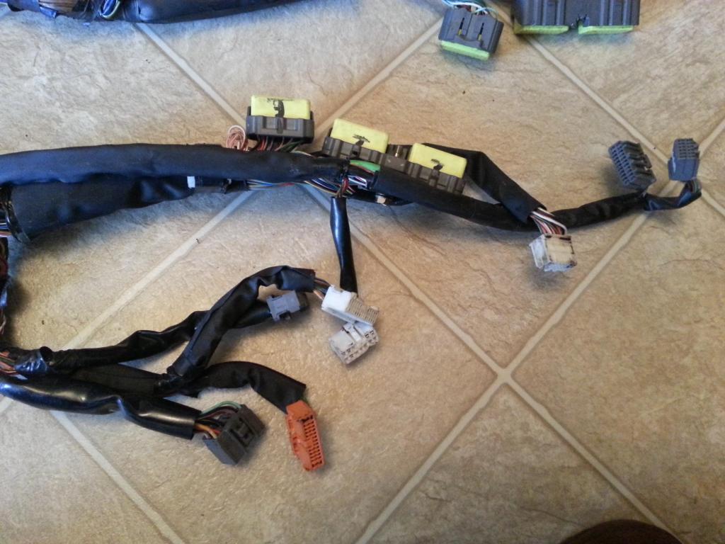
I hope that up to this point , you have done and understood what I have said so far (probably not the previous wiring diagrams but that is alright , you really don't need them) . You at least need to understand what we have talked about so far because THE DRILL will be a repititious job . It will be done over and over on all the plugs of the Aristo 2jzgte harness. I am not gonna explain how to do it again. I will just say , "Now you do THE DRILL " and would expect you to have the results we have here.
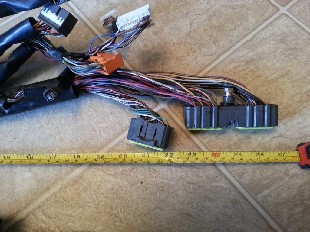
Remember me saying , as much as possible , do not leave a group of connectors until you are done with all the pins / wiring associated with them ? Observing the picture below , you know that all the pins inside the blue ellipsis had already been covered. Some of those pins for the 12 pin Igniter Connector go to the ignition coils. It is just but proper that we work on those ignition coils now since we have worked on all the Pins # 2 of those coils. You see the coils in yellow ellipsis.
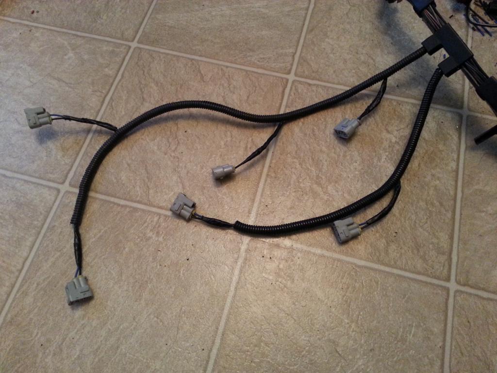
You see the ignition coil plugs at the center.
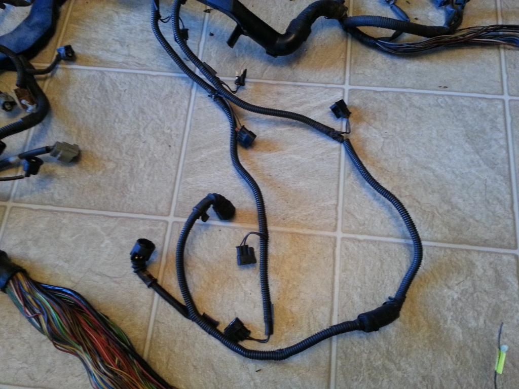
The last two plugs that are after the coil plugs are for the VSVs. If you are not using the stock twin turbos, their plugs and wiring can be removed or reused for something else.
Remember me saying , as much as possible , do not leave a group of connectors until you are done with all the pins / wiring associated with them ? Observing the picture below , you know that all the pins inside the blue ellipsis had already been covered. Some of those pins for the 12 pin Igniter Connector go to the ignition coils. It is just but proper that we work on those ignition coils now since we have worked on all the Pins # 2 of those coils. You see the coils in yellow ellipsis.

You see the ignition coil plugs at the center.


The last two plugs that are after the coil plugs are for the VSVs. If you are not using the stock twin turbos, their plugs and wiring can be removed or reused for something else.
Last edited by gerrb; 01-31-14 at 02:16 PM.
01-31-14, 02:11 PM
#24
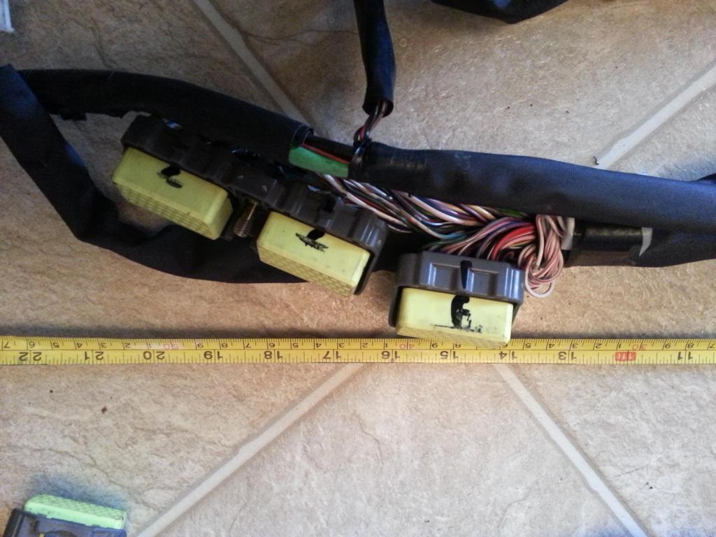
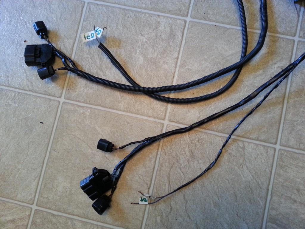
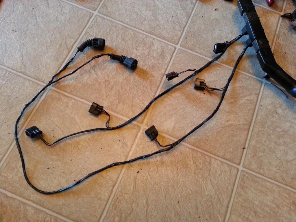
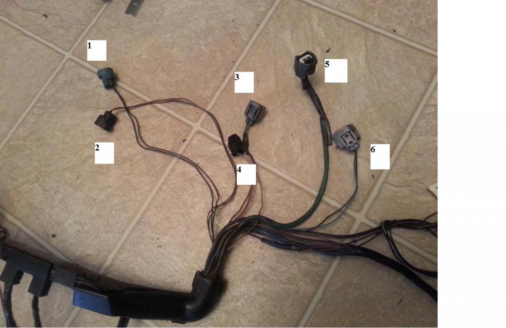
Pictures of the Ignition coils connectors .. from right to left you have Ignition Coil #1 , #2 , #3 , #4 , #5 , #6 and then the 2 VSV connectors
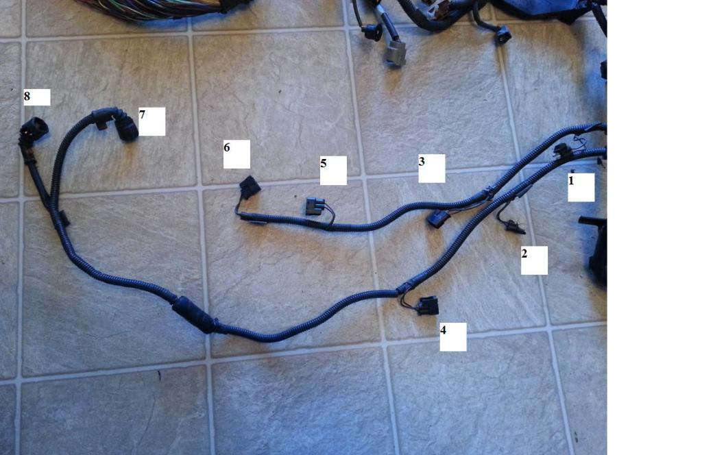
Info you need so you can do THE DRILL .
As pictured above we have
1) Ignition Coil Plug 1
Pin 1 of the Ignition Coil Plug 1 goes to Pin 1 of the Noise Filter & goes to Pin 2 of the 4 pin Igniter Connector & goes to Pin 1 of Ignition Coil 2 , 3, 4, 5, 6 ( & should go to ( SC3 IJ1-7 , SC4 EB2-2 , MK4 IJ1-1 or IJ1-9))
Pin 2 of the Ignition Coil Plug 1 goes to Pin 6 of the 12 Pin Igniter Connector
2) Ignition Coil Plug 2
Pin 1 of the Ignition Coil Plug 2 goes to Pin 1 of the Noise Filter & goes to Pin 2 of the 4 pin Igniter Connector & goes to Pin 1 of Ignition Coil 1, 3, 4, 5, 6 ( & should go to ( SC3 IJ1-7 , SC4 EB2-2 , MK4 IJ1-1 or IJ1-9))
Pin 2 of the Ignition Coil Plug 2 goes to Pin 5 of the 12 Pin Igniter Connector
3) Ignition Coil Plug 3
Pin 1 of the Ignition Coil Plug 3 goes to Pin 1 of the Noise Filter & goes to Pin 2 of the 4 pin Igniter Connector & goes to Pin 1 of Ignition Coil 1 , 2, 4, 5, 6 ( & should go to ( SC3 IJ1-7 , SC4 EB2-2 , MK4 IJ1-1 or IJ1-9))
Pin 2 of the Ignition Coil Plug 3 goes to Pin 4 of the 12 Pin Igniter Connector
4) Ignition Coil Plug 4
Pin 1 of the Ignition Coil Plug 4 goes to Pin 1 of the Noise Filter & goes to Pin 2 of the 4 pin Igniter Connector & goes to Pin 1 of Ignition Coil 1 , 2, 3, 5, 6 ( & should go to ( SC3 IJ1-7 , SC4 EB2-2 , MK4 IJ1-1 or IJ1-9))
Pin 2 of the Ignition Coil Plug 4 goes to Pin 10 of the 12 Pin Igniter Connector
5) Ignition Coil Plug 5
Pin 1 of the Ignition Coil Plug 5 goes to Pin 1 of the Noise Filter & goes to Pin 2 of the 4 pin Igniter Connector & goes to Pin 1 of Ignition Coil 1 , 2, 3, 4, 6 ( & should go to ( SC3 IJ1-7 , SC4 EB2-2 , MK4 IJ1-1 or IJ1-9))
Pin 2 of the Ignition Coil Plug 5 goes to Pin 11 of the 12 Pin Igniter Connector
6) Ignition Coil Plug 6
Pin 1 of the Ignition Coil Plug 6 goes to Pin 1 of the Noise Filter & goes to Pin 2 of the 4 pin Igniter Connector & goes to Pin 1 of Ignition Coil 1 , 2, 3, 4, 5 ( & should go to ( SC3 IJ1-7 , SC4 EB2-2 , MK4 IJ1-1 or IJ1-9))
Pin 2 of the Ignition Coil Plug 6 goes to Pin 12 of the 12 Pin Igniter Connector
7) VSV1 ( Intake Air Control Valve )
Pin 1 of the VSV1 goes to Pin 1 of the VSV3 & goes to Pin 2 of the Oxygen Sensor Connector ( & should go to Pin 12 of the Data Link Connector & to ( SC3 IJ1-12 & EB2-1 & Short-4 , SC4 IJ1-12 & EB2-3 , MK4 EA3-3 ))
Pin 2 of the VSV1 goes to Pin 40 of the 80 pin ECU Connector
8) VSV3( Exhaust Bypass Valve )
Pin 1 of the VSV3 goes to Pin 1 of the VSV1 & goes to Pin 2 of the Oxygen Sensor Connector ( & should go to Pin 12 of the Data Link Connector & to ( SC3 IJ1-12 & EB2-1 & Short-4 , SC4 IJ1-12 & EB2-3 , MK4 EA3-3 ))
Pin 2 of the VSV3 goes to Pin 38 of the 80 pin ECU Connector
Now it is time for you guys to do THE DRILL ( You already know this , right ?)
Last edited by gerrb; 01-31-14 at 02:17 PM.
01-31-14, 02:17 PM
#25
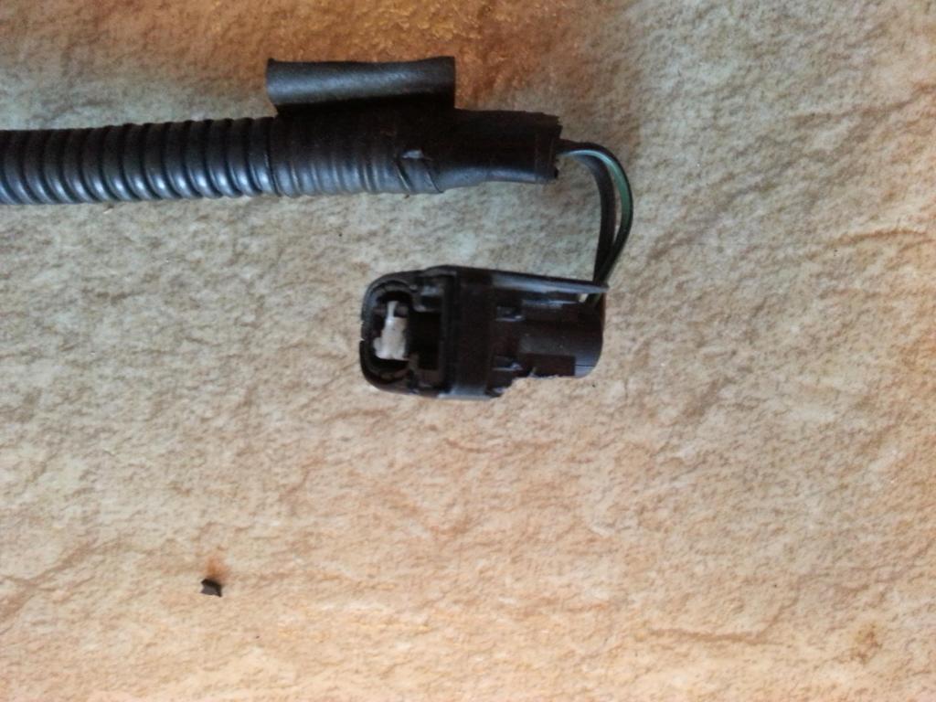
On the harnesses am working on , I have inspected the physical conditions of the plugs.
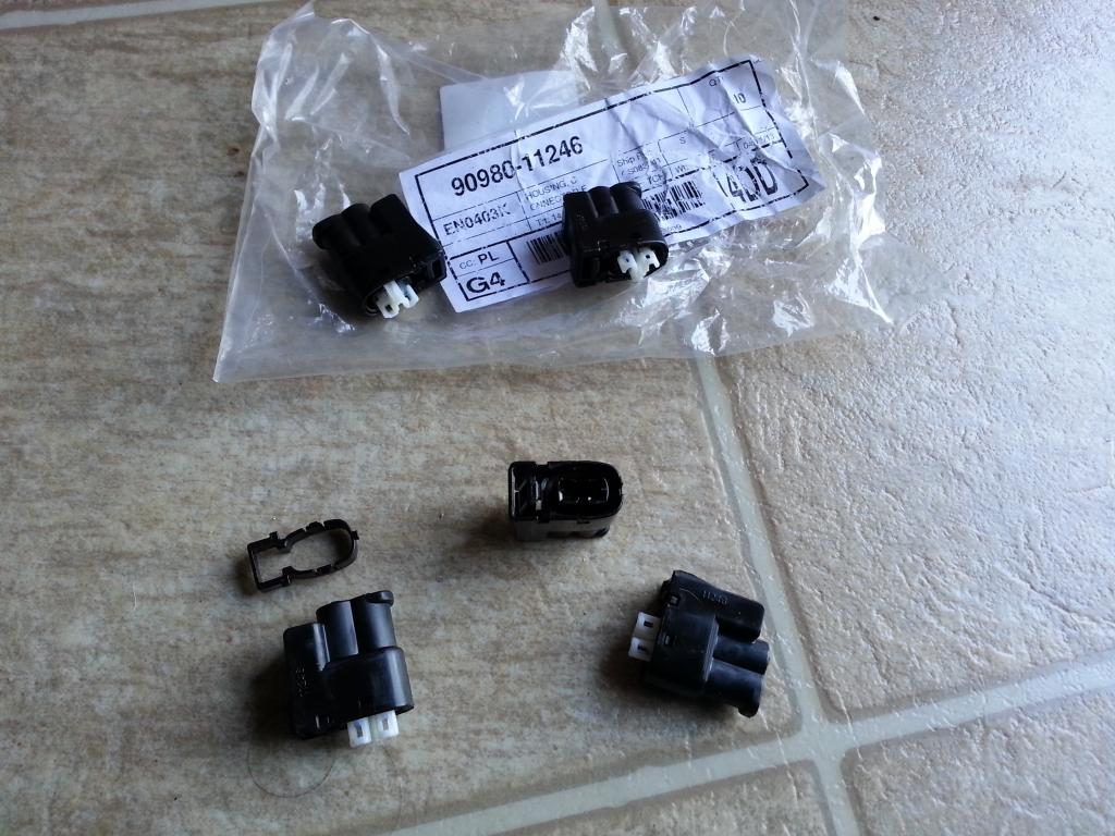
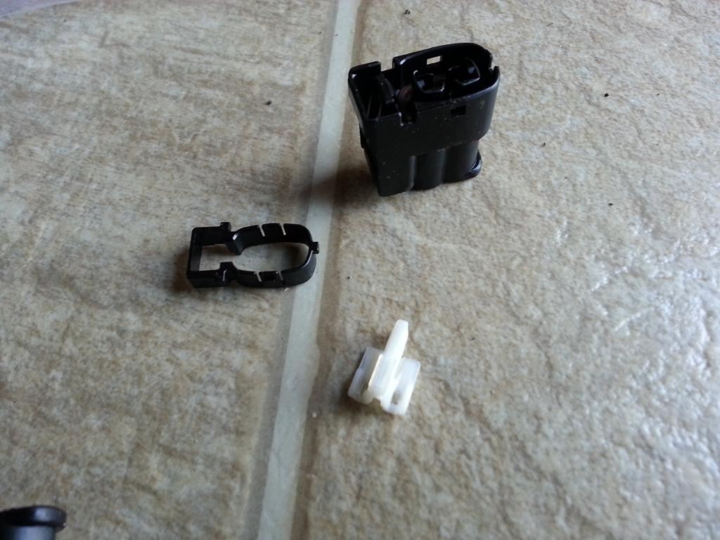
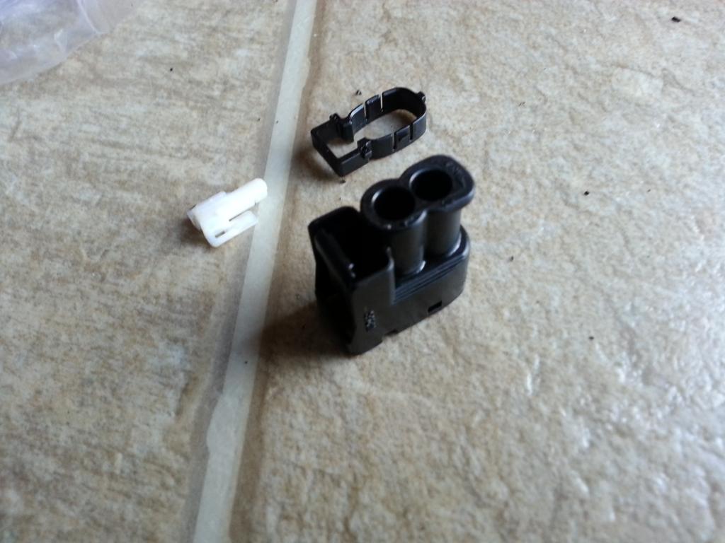
This casing is damaged so it needs to be replaced. Be mindful of where you install the pins where you replace the plug.
Plastic inserts to hold the two pins inside the plug casing are missing.
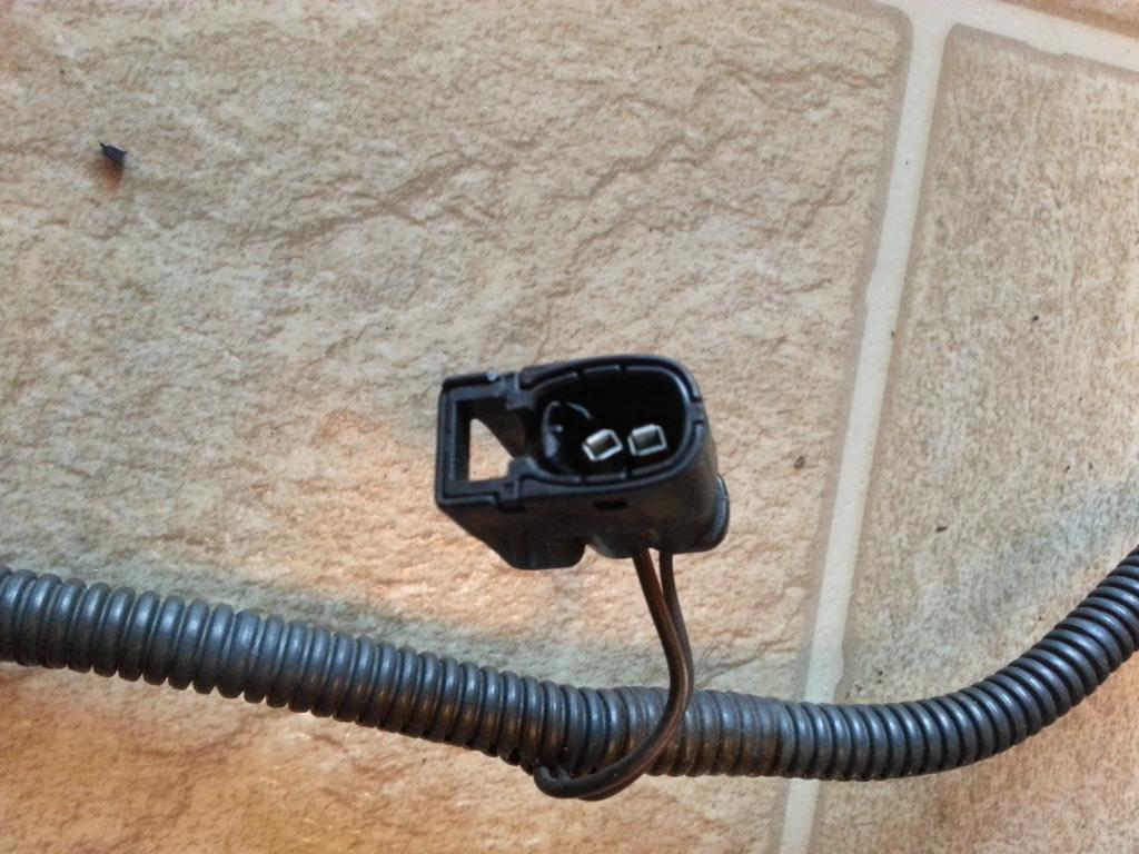
This is how the black and white plastic inserts look like.
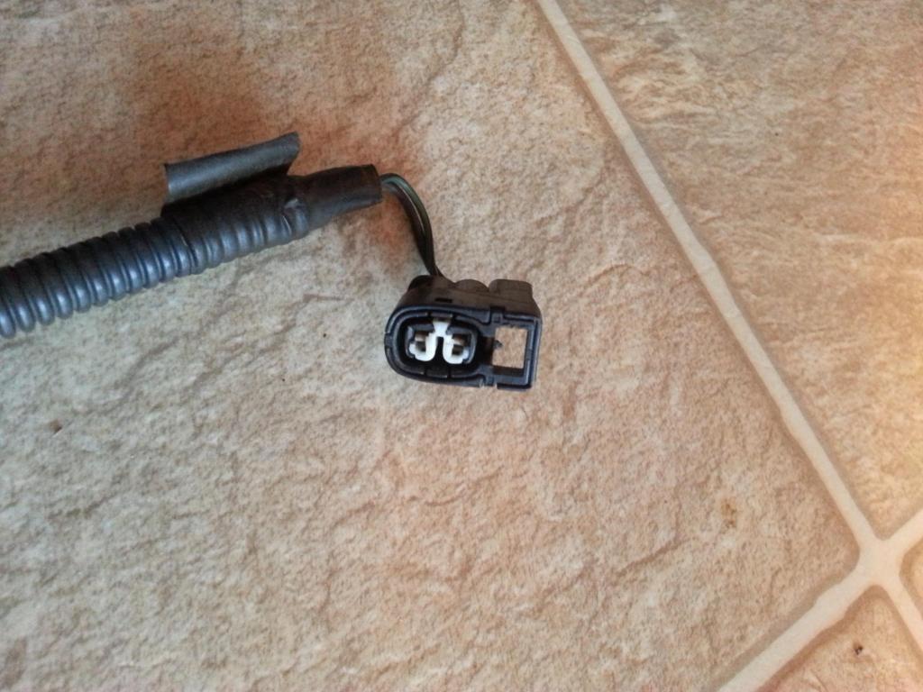
This one has the the plastic inserts but the lock is bad.
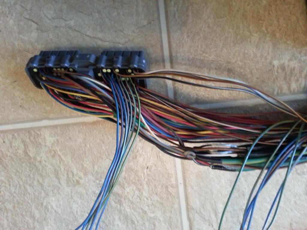
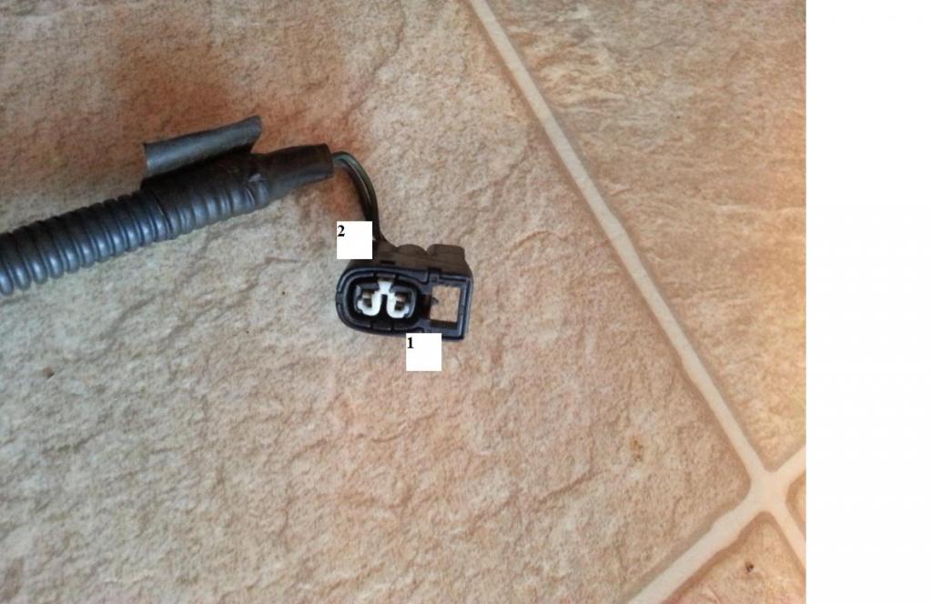
For the Ignition Coil connectors , here are the pin numbering , pin #1 is nearer the lock
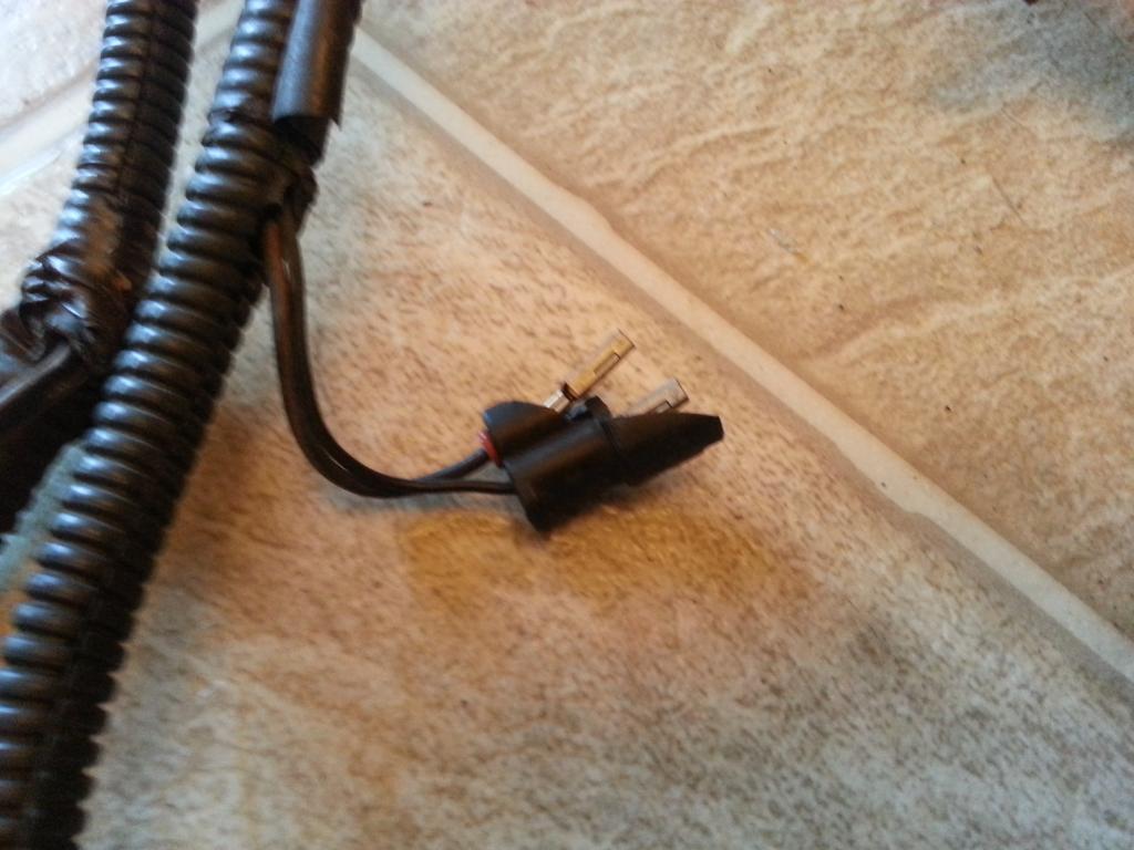
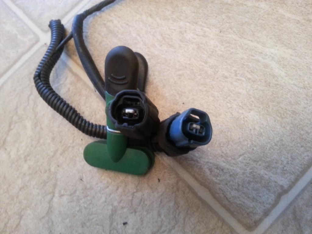
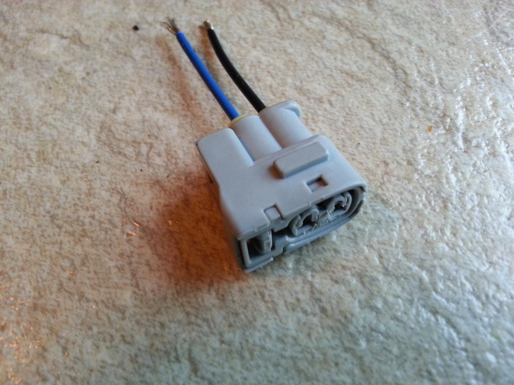
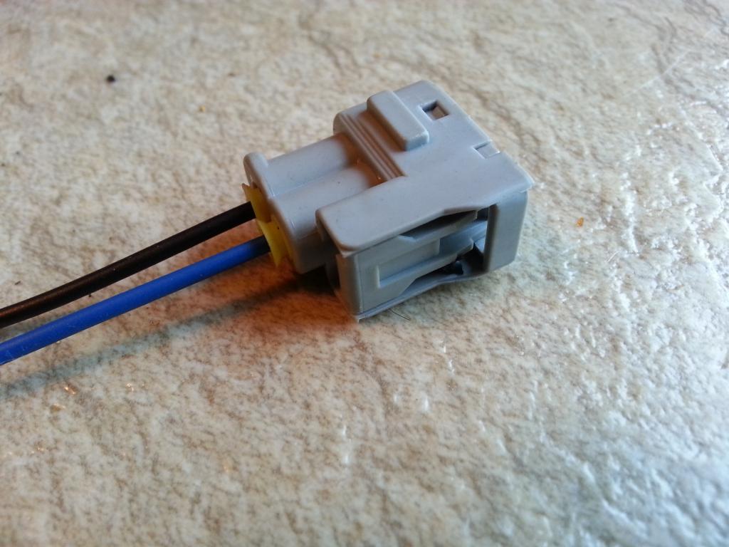
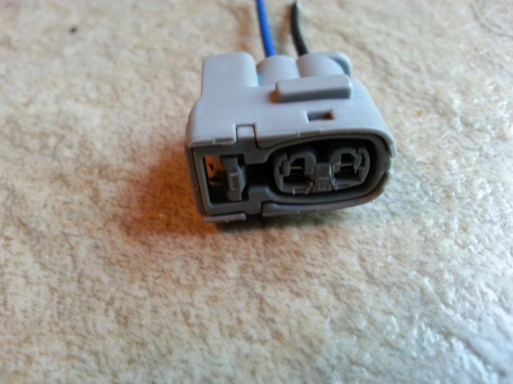
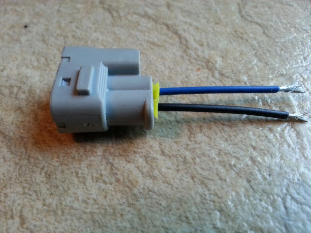
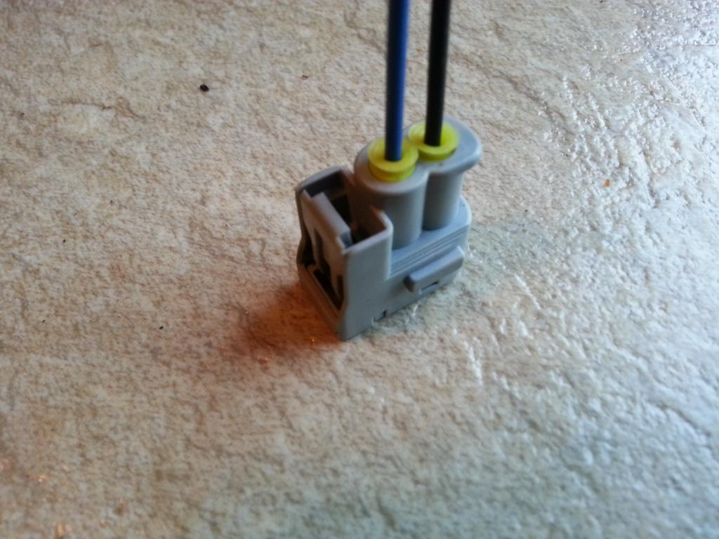
Here is a close up look of the VSV plugs and by now I hope you remember which is pin 1 and pin 2 of every VSV plug (remember ? holding the connector with the lock on top , pin1 is the first on the left ) .
The blue one is VSV1 which is for the Air Intake Control Valve
The black one is VSV3 which is for the Exhaust Bypass Valve
This is a JDM Supra with 2jzgte , you see were the VSVs are laid out
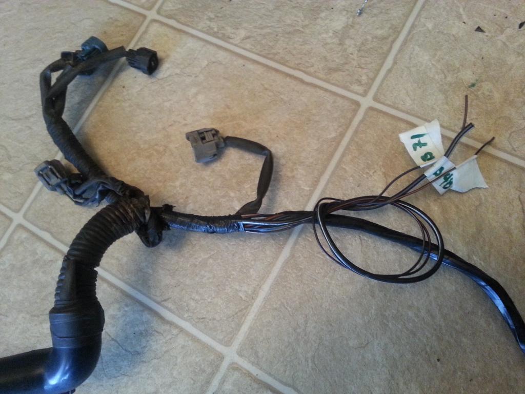
Cleaned up the wrap on that part of the harness where the ignition coil connectors are.
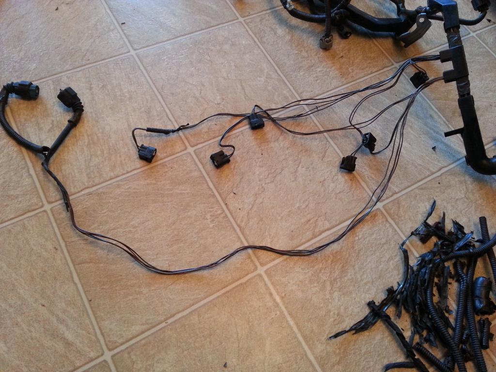
Now that part of the harness is unwrapped , it is easy to remove the plugs and wires we do not need. Like if you are going single turbo or aftermarket twins , the wires and plugs for the VSVs are not needed. If you are going stock twin turbo , do not remove those, just make sure the connectors are good.
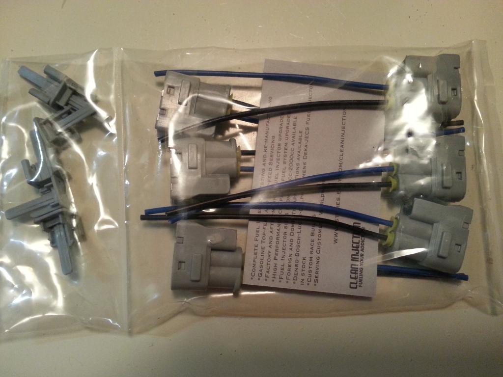
Aaron bought new ignition coil pigtails for his harness. He bought aftermarket plugs and were cheaper than the OEM plugs I bought for mine .
This casing is damaged so it needs to be replaced. Be mindful of where you install the pins where you replace the plug.

Plastic inserts to hold the two pins inside the plug casing are missing.

This is how the black and white plastic inserts look like.

This one has the the plastic inserts but the lock is bad.

For the Ignition Coil connectors , here are the pin numbering , pin #1 is nearer the lock

Here is a close up look of the VSV plugs and by now I hope you remember which is pin 1 and pin 2 of every VSV plug (remember ? holding the connector with the lock on top , pin1 is the first on the left ) .
The blue one is VSV1 which is for the Air Intake Control Valve
The black one is VSV3 which is for the Exhaust Bypass Valve

This is a JDM Supra with 2jzgte , you see were the VSVs are laid out

Cleaned up the wrap on that part of the harness where the ignition coil connectors are.

Now that part of the harness is unwrapped , it is easy to remove the plugs and wires we do not need. Like if you are going single turbo or aftermarket twins , the wires and plugs for the VSVs are not needed. If you are going stock twin turbo , do not remove those, just make sure the connectors are good.
Aaron bought new ignition coil pigtails for his harness. He bought aftermarket plugs and were cheaper than the OEM plugs I bought for mine .


Last edited by gerrb; 01-31-14 at 02:20 PM.
01-31-14, 02:19 PM
#26
The aftermarket plugs were nice. My only gripe was some wires were not properly crimped inside the plug .
Aaron's harness with ignition coil plugs replaced and the two VSV plugs & wires pulled out from that area .
Since he didn't need the 2 VSV plugs , pulled them out from that area and labeled the two wires that go direct to the 80 pin ECU connector
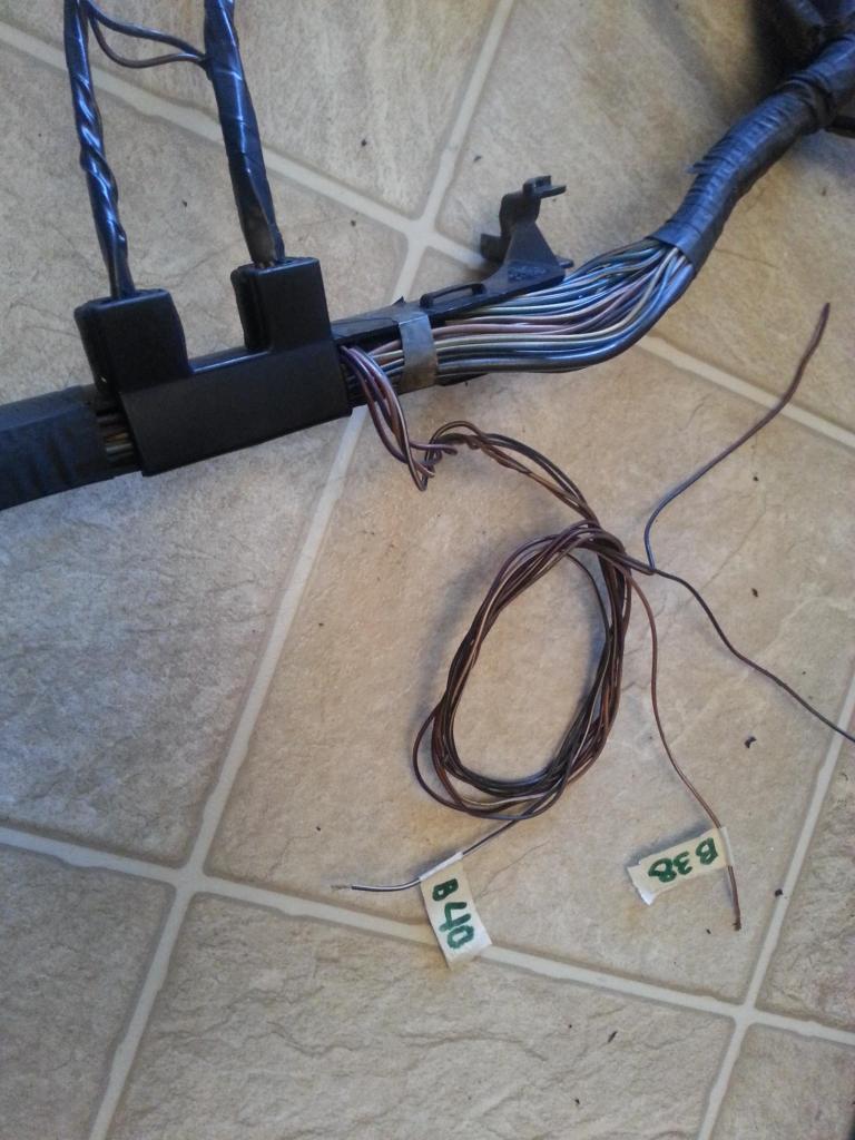
Extended the wires .
Pulled those wires nearer the ECU Connectors
Took the pins out of the 80 pin ECU connector and labeled them
For Aaron's harness , you see that I used also the oxygen sensor wires as extra wires so I had to label them accordingly too.
Stock / OEM coil plug housing for my Red Mamba 1
Ignition Coil Plugs and VSV3 plug for my Red Mamba 2 had been replaced . As you probably noticed I am not wrapping mine with corrugated flexible hose yet . It is because I have none as of this writing .
.
For Aaron's and my Red Mamba 1 harness, we re-used the wires of the oxygen sensor for our Boost Solenoid since one is a B+ supply and one goes directly to pin 71 . Temporarily so they are out of the way , rolled them but labeled them though so it is easy for me to know which is which later.
Before I forget , let me add something here ...
Pin 48 of the ECU 80 pin connector is for the signal of the Oxygen Sensor , it gives a feedback to the ECU on how much is the air fuel ratio measured at the exhaust so the ECU can actually adjust fuel trim for the injectors. This wire is SHIELDED . Observe it , it is thicker because of the shield around the middle / signal wire . Most signal wires which are very important to the ECU are shielded just like the cam and crank sensors signal wires so to prevent any interference. We will leave it like that . I won't explain what interference and from where so as not to confuse non electrical people. That won't stop you from going ahead anyway. It would suffice to know that you will have to extend the wire after the shield , nearer the connector itself. Also you will find another wire almost same wire with shield connected to that wire , it goes to a pin in the diagnostic port which we will tackle later.
Did probe for connectivities for all the wires like PIn 2 of Ignition Coil 6 and Pin 12 of the 12 Pin Igniter Connector .
Aaron's harness with ignition coil plugs replaced and the two VSV plugs & wires pulled out from that area .

Since he didn't need the 2 VSV plugs , pulled them out from that area and labeled the two wires that go direct to the 80 pin ECU connector

Extended the wires .

Pulled those wires nearer the ECU Connectors

Took the pins out of the 80 pin ECU connector and labeled them

For Aaron's harness , you see that I used also the oxygen sensor wires as extra wires so I had to label them accordingly too.

Stock / OEM coil plug housing for my Red Mamba 1


Ignition Coil Plugs and VSV3 plug for my Red Mamba 2 had been replaced . As you probably noticed I am not wrapping mine with corrugated flexible hose yet . It is because I have none as of this writing
.
For Aaron's and my Red Mamba 1 harness, we re-used the wires of the oxygen sensor for our Boost Solenoid since one is a B+ supply and one goes directly to pin 71 . Temporarily so they are out of the way , rolled them but labeled them though so it is easy for me to know which is which later.

Before I forget , let me add something here ...
Pin 48 of the ECU 80 pin connector is for the signal of the Oxygen Sensor , it gives a feedback to the ECU on how much is the air fuel ratio measured at the exhaust so the ECU can actually adjust fuel trim for the injectors. This wire is SHIELDED . Observe it , it is thicker because of the shield around the middle / signal wire . Most signal wires which are very important to the ECU are shielded just like the cam and crank sensors signal wires so to prevent any interference. We will leave it like that . I won't explain what interference and from where so as not to confuse non electrical people. That won't stop you from going ahead anyway. It would suffice to know that you will have to extend the wire after the shield , nearer the connector itself. Also you will find another wire almost same wire with shield connected to that wire , it goes to a pin in the diagnostic port which we will tackle later.
Did probe for connectivities for all the wires like PIn 2 of Ignition Coil 6 and Pin 12 of the 12 Pin Igniter Connector .


Last edited by gerrb; 01-31-14 at 02:23 PM.
01-31-14, 02:21 PM
#27
You have done THE DRILL on the set of plugs we are working on so it is time to update your Chart .
I know that chart is a lot of work . If you are very familiar where a pin should go , you don't need it. But if you are new and want a quick guide later on then do it.. It lets you see at a glance what you have worked on and checked / verified . It will be more valuable for those who cannot read wiring diagrams.
80 PIN ECU CONNECTOR
1
2
10
20
30
38 <--> Pin 2 of the VSV3 CHECKED
40 <--> Pin 2 of the VSV1 CHECKED
48 <--> Pin 3 of the O2 Sensor CHECKED
50
51
52 <--> Pin 7 of the 12 pin Igniter Connector CHECKED
53 <--> Pin 8 of the 12 pin igniter Connector CHECKED
54 <--> Pin 9 of the 12 pin igniter Connector CHECKED
55 <--> Pin 3 of the 12 pin igniter Connector CHECKED
56 <--> Pin 2 of the 12 pin Igniter Connector CHECKED
57 <--> Pin 1 of the 12 pin Igniter Connector CHECKED
58 <--> Pin 3 of the 4 pin Igniter Connector CHECKED
59
60
70
71 <--> Pin 1 of the O2 Sensor CHECKED
80
4 PIN IGNITER CONNECTOR
1 <--> Pin 12 of Plug F of Aristo plug <--> ( Pin 19 of the Data Link Connector <--> ( SC3 IK1-8 , SC4 IK1-8 , MK4 ))
2 <--> Pin 6 of Plug F of Aristo plug <--> Pin 1 of the Noise Filter <--> ( SC3 IJ1-7 , SC4 EB2-2 , MK4 IJ1-1 or IJ1-9 )
3 <--> Pin 58 of the 80 pin ECU connector CHECKED
4 <--> Ground Connector on the Front Side of Intake Manifold <--> Pin 2 of the Noise filter Connector CHECKED
12 PIN IGNITER CONNECTOR
1 <--> Pin 57 of the 80 pin ECU connector CHECKED
2 <--> Pin 56 of the 80 pin ECU connector CHECKED
3 <--> Pin 55 of the 80 pin ECU connector CHECKED
4 <--> Pin 2 of the Ignition Coil Connector 3 CHECKED
5 <--> Pin 2 of the Ignition Coil Connector 2 CHECKED
6 <--> Pin 2 of the Ignition Coil Connector 1 CHECKED
7 <--> Pin 52 of the 80 pin ECU connector CHECKED
8 <--> Pin 53 of the 80 pin ECU connector CHECKED
9 <--> Pin 54 of the 80 pin ECU connector CHECKED
10 <--> Pin 2 of the Ignition Coil Connector 4 CHECKED
11 <--> Pin 2 of the Ignition Coil Connector 5 CHECKED
12 <--> Pin 2 of the Ignition Coil Connector 6 CHECKED
IGNITION COIL 1
1 <--> Pin 1 of the Noise Filter <--> Pin 2 of the 4 pin Igniter Connector <--> Pin 1 of Ignition Coil 2,3,4,5,6 <-->( SC3 IJ1-7 , SC4 EB2-2 , MK4 IJ1-1 or IJ1-9 )
2 <--> Pin 6 of the 12 Pin Igniter Connector CHECKED
IGNITION COIL 2
1 <--> Pin 1 of the Noise Filter <--> Pin 2 of the 4 pin Igniter Connector <--> Pin 1 of Ignition Coil 1,3,4,5,6 <-->( SC3 IJ1-7 , SC4 EB2-2 , MK4 IJ1-1 or IJ1-9 )
2 <--> Pin 5 of the 12 Pin Igniter Connector CHECKED
IGNITION COIL 3
1 <--> Pin 1 of the Noise Filter <--> Pin 2 of the 4 pin Igniter Connector <--> Pin 1 of Ignition Coil 1,2,4,5,6 <-->( SC3 IJ1-7 , SC4 EB2-2 , MK4 IJ1-1 or IJ1-9 )
2 <--> Pin 4 of the 12 Pin Igniter Connector CHECKED
IGNITION COIL 4
1 <--> Pin 1 of the Noise Filter <--> Pin 2 of the 4 pin Igniter Connector <--> Pin 1 of Ignition Coil 1,2,3,5,6 <-->( SC3 IJ1-7 , SC4 EB2-2 , MK4 IJ1-1 or IJ1-9 )
2 <--> Pin 10 of the 12 Pin Igniter Connector CHECKED
IGNITION COIL 5
1 <--> Pin 1 of the Noise Filter <--> Pin 2 of the 4 pin Igniter Connector <--> Pin 1 of Ignition Coil 1,2,3,4,6 <-->( SC3 IJ1-7 , SC4 EB2-2 , MK4 IJ1-1 or IJ1-9 )
2 <--> Pin 11 of the 12 Pin Igniter Connector CHECKED
IGNITION COIL 6
1 <--> Pin 1 of the Noise Filter <--> Pin 2 of the 4 pin Igniter Connector <--> Pin 1 of Ignition Coil 1,2,3,4,5 <-->( SC3 IJ1-7 , SC4 EB2-2 , MK4 IJ1-1 or IJ1-9 )
2 <--> Pin 12 of the 12 Pin Igniter Connector CHECKED
NOISE FILTER
1 <--> Pin 2 of the 4 pin Igniter Connector <--> ( SC3 IJ1-7, SC4 EB2-2 , MK4 IJ1-1 or IJ1-9 )
2 <--> Ground Connector on the Front Side of Intake Manifold <--> Pin 4 of the 4 pin Igniter Connector CHECKED
The following plugs are necessary only if you are going stock 2jzgte setup
Oxygen Sensor O2
1 <--> Pin 71 of the 80 pin ECU Connector CHECKED
2 <--> Pin 3 of Plug E of Aristo Plug <-> (Pin 12 of the Data Link Connector <--> ( SC3 IJ1-12 & EB2-1 & Short-4 , SC4 IJ1-12 & EB2-3 , MK4 EA3-3 ))
3 <--> Pin 48 of the 80 pin ECU Connector CHECKED
VSV1 ( Air Intake Control Valve )
1 <--> Pin 2 of the Oxygen Sensor Connector <--> Pin 1 of the VSV3 <-> (Pin 12 of the Data Link Connector <--> ( SC3 IJ1-12 & EB2-1 & Short-4 , SC4 IJ1-12 & EB2-3 , MK4 EA3-3 ))
2 <--> Pin 40 of the 80 pin ECU Connector CHECKED
VSV3( Exhaust Bypass Valve )
1 <--> Pin 2 of the Oxygen Sensor Connector <-->Pin 1 of the VSV1 <-> (Pin 12 of the Data Link Connector <--> ( SC3 IJ1-12 & EB2-1 & Short-4 , SC4 IJ1-12 & EB2-3 , MK4 EA3-3 ))
2 <--> Pin 38 of the 80 pin ECU Connector CHECKED
The following plugs needs to be taken out
BIG GRAY ARISTO PLUG
PLUG E
3 <--> Pin 2 of Oxygen Sensor <--> (Pin 12 of the Data Link Connector <--> ( SC3 IJ1-12 & EB2-1 & Short-4 , SC4 IJ1-12 & EB2-3 , MK4 EA3-3 ))
PLUG F
6 <--> Pin 1 of the Noise Filter <--> ( SC3 IJ1-7 , SC4 EB2-2 , MK4 IJ1-1 or IJ1-9 )
12 <--> ( Pin 19 of the Data Link Connector & to ( SC3 IK1-8 , SC4 IK1-8 , MK4 ))
Last edited by gerrb; 01-31-14 at 02:26 PM.
01-31-14, 02:22 PM
#28
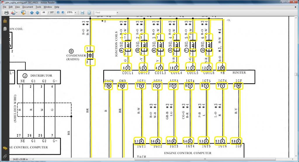
DIAGRAMS TO VERIFY PIN NUMBERING & WHERE THE WIRE GOES
*** Ignition Coils ***
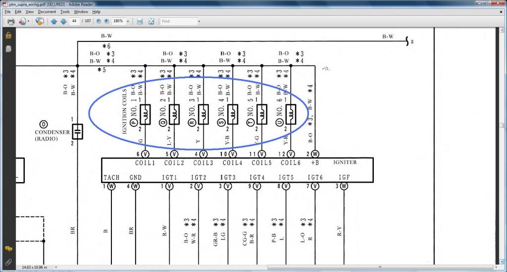
In the diagram above we don't see the Pin 1 of all the Coil Plugs being connected to ( SC3 IJ1-7 , SC4 EB2-2 , MK4 IJ1-1 or IJ1-9) but we see them to be connected to Pin 1 of the Noise Filter and to Pin 2 of the 4 pin Igniter Connector. And we have proven this two pins to be connected to ( SC3 IJ1-7 , SC4 EB2-2 , MK4 IJ1-1 or IJ1-9) . Ergo , Pin 1 of all the Coil Plugs are connected to ( SC3 IJ1-7 , SC4 EB2-2 , MK4 IJ1-1 or IJ1-9) . Are you convinced ? If not , go over the previous diagrams .
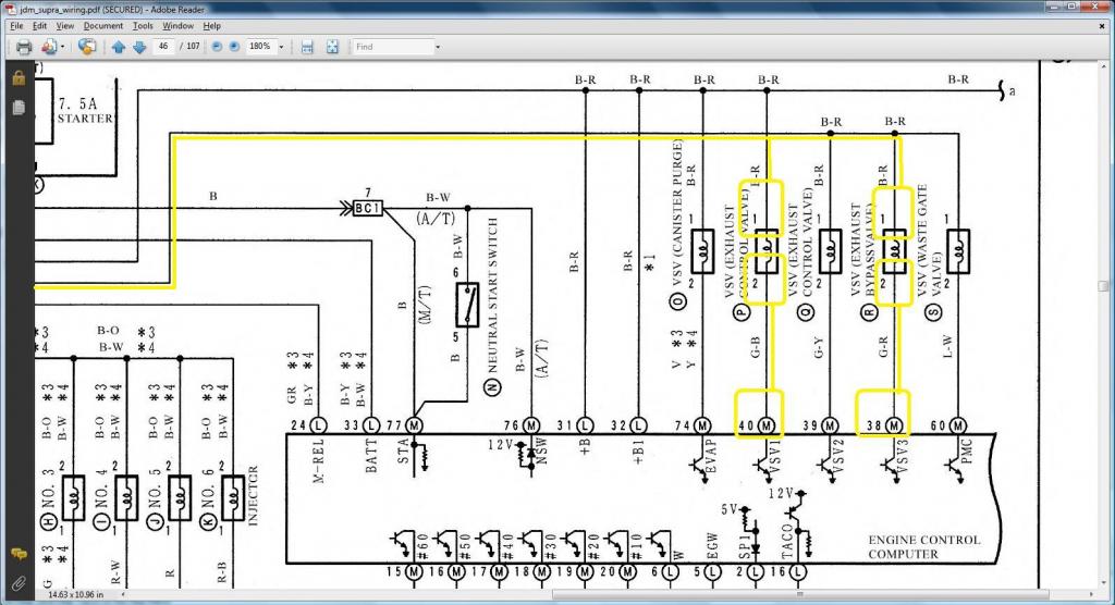
*** VSV 1 & VSV2 ***
There are things I noticed on this diagram . 1) The VSV1 is labeled Exhaust Control Valve for which there is a duplicate which is VSV2 as you can see on the diagram. I checked the USDM Wiring Diagram Pin 40 is the Air Intake Control Valve so I labeled it as such. 2) On this diagram, you don't see Pin 1 of VSV1 connected to Pin 1 of VSV3 . On this one , just trust me , they meet through another plug. 3) When I was probing my Aristo harness on these VSVs , looks to me their Pin 2 were interchanged on my harness . What I mean is Pin 2 of VSV1 was going to pin 38 of the 80 pin ECU connector and the Pin 2 of VSV3 was going to to pin 40 of the 80 pin ECU connector which is not according to the diagram below. I did check this diagram against the USDM diagram , pin numberings are correct so I am guessing someone played around with my actual Aristo harness VSV1 and VSV3 pins.
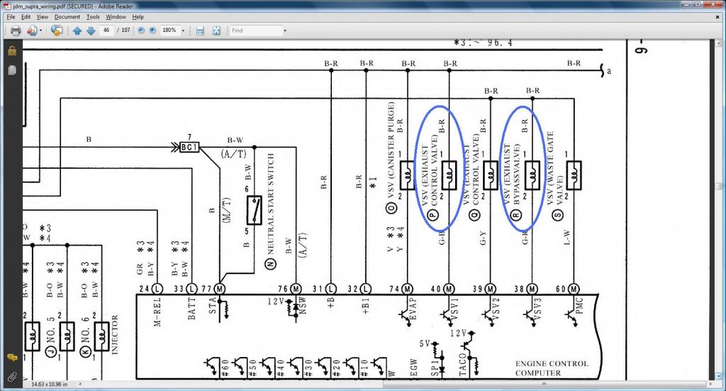
In the diagram above you don't see the connectivity of Pin 1 of VSV1 & VSV3 to Pin 2 of the Oxygen Sensor so am posting this diagram and you follow what is in Orange to prove that there is connectivity between them.
Do you remember that we have shown previously through the diagrams that Pin 2 of the Oxygen Sensor goes to (Pin 12 of the Data Link Connector & goes to ( SC3 IJ1-12 & EB2-1 & Short-4 , SC4 IJ1-12 & EB2-3 , MK4 EA3-3 )) . Since we have shown in the above picture that Pin 1 of VSV1 & VSV3 goes to Pin 2 of the Oxygen Sensor , I guess it goes without saying that Pin1 of VSV1 & VSV3 goes to (Pin 12 of the Data Link Connector & goes to ( SC3 IJ1-12 & EB2-1 & Short-4 , SC4 IJ1-12 & EB2-3 , MK4 EA3-3 ))
CONFUSING ? DON'T WORRY ABOUT IT THEN . AS I HAVE SAID ,YOU REALLY DON'T NEED THESE DIAGRAMS I AM POSTING
  !
!
*** Ignition Coils ***

In the diagram above we don't see the Pin 1 of all the Coil Plugs being connected to ( SC3 IJ1-7 , SC4 EB2-2 , MK4 IJ1-1 or IJ1-9) but we see them to be connected to Pin 1 of the Noise Filter and to Pin 2 of the 4 pin Igniter Connector. And we have proven this two pins to be connected to ( SC3 IJ1-7 , SC4 EB2-2 , MK4 IJ1-1 or IJ1-9) . Ergo , Pin 1 of all the Coil Plugs are connected to ( SC3 IJ1-7 , SC4 EB2-2 , MK4 IJ1-1 or IJ1-9) . Are you convinced ? If not , go over the previous diagrams .
*** VSV 1 & VSV2 ***
There are things I noticed on this diagram . 1) The VSV1 is labeled Exhaust Control Valve for which there is a duplicate which is VSV2 as you can see on the diagram. I checked the USDM Wiring Diagram Pin 40 is the Air Intake Control Valve so I labeled it as such. 2) On this diagram, you don't see Pin 1 of VSV1 connected to Pin 1 of VSV3 . On this one , just trust me
, they meet through another plug. 3) When I was probing my Aristo harness on these VSVs , looks to me their Pin 2 were interchanged on my harness . What I mean is Pin 2 of VSV1 was going to pin 38 of the 80 pin ECU connector and the Pin 2 of VSV3 was going to to pin 40 of the 80 pin ECU connector which is not according to the diagram below. I did check this diagram against the USDM diagram , pin numberings are correct so I am guessing someone played around with my actual Aristo harness VSV1 and VSV3 pins.
In the diagram above you don't see the connectivity of Pin 1 of VSV1 & VSV3 to Pin 2 of the Oxygen Sensor so am posting this diagram and you follow what is in Orange to prove that there is connectivity between them.

Do you remember that we have shown previously through the diagrams that Pin 2 of the Oxygen Sensor goes to (Pin 12 of the Data Link Connector & goes to ( SC3 IJ1-12 & EB2-1 & Short-4 , SC4 IJ1-12 & EB2-3 , MK4 EA3-3 )) . Since we have shown in the above picture that Pin 1 of VSV1 & VSV3 goes to Pin 2 of the Oxygen Sensor , I guess it goes without saying that Pin1 of VSV1 & VSV3 goes to (Pin 12 of the Data Link Connector & goes to ( SC3 IJ1-12 & EB2-1 & Short-4 , SC4 IJ1-12 & EB2-3 , MK4 EA3-3 ))
CONFUSING
? DON'T WORRY ABOUT IT THEN . AS I HAVE SAID ,YOU REALLY DON'T NEED THESE DIAGRAMS I AM POSTING !
Last edited by gerrb; 01-31-14 at 02:30 PM.
01-31-14, 02:24 PM
#29
So at this point , we are done with the Ignition Coil Plugs ,2 Igniter Plugs , Noise Filter Plug , Oxygen Sensor Plug and 2 VSV Plugs.
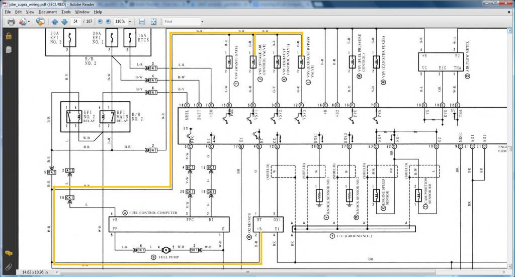
The following pictures is just another way of showing what we have done so far ... in yellow marker .
Ignition Control which includes the Igniter , Noise Filter
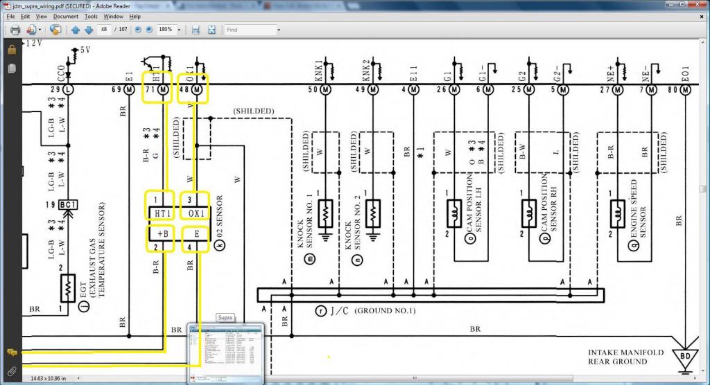
Engine Control - Oxygen Sensor
Engine Control - 2 VSVs
Are you ready to go to the next group of connectors ?
The following pictures is just another way of showing what we have done so far ... in yellow marker .
Ignition Control which includes the Igniter , Noise Filter

Engine Control - Oxygen Sensor

Engine Control - 2 VSVs

Are you ready to go to the next group of connectors ?
Last edited by gerrb; 01-31-14 at 03:15 PM.
01-31-14, 02:36 PM
#30
Now let's go to the next set of connectors farthest to the ECU connectors. That leads us to these . Partly seen are the rolled wires that where from the Oxygen Sensor
The Info you need so you can do THE DRILL .
1) VSVPMC ( Blue - Waste Gate Valve )
Pin 1 of VSVPMC goes to Pin 1 of VSV1 , VSV2 , VSV 3 ( & should go to Pin 12 of the Data Link Connector & to ( SC3 IJ1-12 & EB2-1 & Short-4 , SC4 IJ1-12 & EB2-3 , MK4 EA3-3 ))
Pin 2 of VSVPMC goes to pin 60 of the 80 pin ECU Connector
2) VSV2 ( Black - Exhaust Control Valve )
Pin 1 of VSV2 goes to Pin 1 of VSV1 , VSV3 . VSVPMC ( & should go to Pin 12 of the Data Link Connector & to ( SC3 IJ1-12 & EB2-1 & Short-4 , SC4 IJ1-12 & EB2-3 , MK4 EA3-3 ))
Pin 2 of VSV2 goes to Pin 39 of the 80 pin ECU Connector
3) Water Temp Coolant Sensor
Pin 1 of the Water Temp Coolant Sensor goes to pin 65 of the 80 pin ECU Connector
Pin 2 of the Water Temp Coolant Sensor goes to pin 44 of the 80 pin ECU Connector
4) Water Temp Gauge Sender
Pin 1 of the Water Temp Gauge Sender goes to Pin 9 of Plug F of Big Gray Aristo Plug(should go to SC3 IK1-9 , SC4 IK1-9 & Short-3 , MK4 II1-19 )
5) Crankshaft Position Sensor ( CPS )
Pin 1 of the Crankshaft Position Sensor goes to Pin 27 of the 80 pin ECU Connector
Pin 2 of the Crankshaft Position Sensor goes to Pin 7 of the 80 pin ECU Connector
6) Hydraulic Cooling Fan Solenoid
Pin 1 of the Hydraulic Cooling Fan Solenoid Connector goes to Pin 13 of Plug C of Big Gray Aristo Plug
Pin 2 of the Hydraulic Cooling Fan Solenoid Connector goes to Pin 9 of Plug D of Big Gray Aristo Plug
Guys , go ahead and do THE DRILL .
Last edited by gerrb; 06-03-14 at 07:40 AM.