2JZGTE Wiring Harness Made Easy
 01-31-14, 04:35 PM
#46

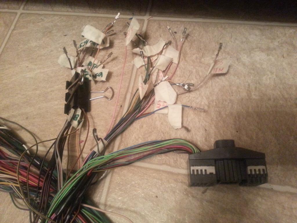
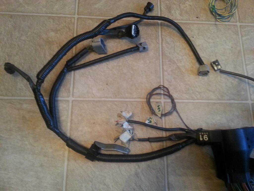
There is nothing much to show on Aaron's and my Red Mamba 2 harness at this point . After all those wires for the Diagnostic Port are removed from the Big Gray Aristo Plug which I bundled so I can easily get into them , you see that there is not much left on that Aristo Plug
Aaron's harness with the VSV removed
On the Red Mamba 2 harness , VSV is there since it will be like a stock harness with auto transmission.


Aaron's harness with the VSV removed

On the Red Mamba 2 harness , VSV is there since it will be like a stock harness with auto transmission.

Last edited by gerrb; 02-01-14 at 05:24 AM.
 01-31-14, 04:36 PM
#47
[Let us update our CHART
80 PIN ECU CONNECTOR
1
2
7 <--> Pin 2 of the Crankshaft Position Sensor CHECKED
10
20 <--> Pin 1 of the Injector No. 1 CHECKED
27 <--> Pin 1 of the Crankshaft Position Sensor CHECKED
30
38 <--> Pin 2 of the VSV3 CHECKED
39 <--> Pin 2 of the VSV2 CHECKED
40 <--> Pin 2 of the VSV1 CHECKED
41 <--> Pin 1 of the TPS <--> Pin 4 of the Sub-TPS CHECKED
42 <--> Pin 3 of the Sub-TPS CHECKED
43 <--> Pin 2 of the TPS CHECKED
44 <--> Pin 2 of the Water Temperature Sensor CHECKED
48 <--> Pin 3 of the O2 Sensor CHECKED
49 <--> Pin 1 of the Knock Sensor 1 CHECKED
50 <--> Pin 1 of the Knock Sensor 1 CHECKED
51
52 <--> Pin 7 of the 12 pin Igniter Connector CHECKED
53 <--> Pin 8 of the 12 pin igniter Connector CHECKED
54 <--> Pin 9 of the 12 pin igniter Connector CHECKED
55 <--> Pin 3 of the 12 pin igniter Connector CHECKED
56 <--> Pin 2 of the 12 pin Igniter Connector CHECKED
57 <--> Pin 1 of the 12 pin Igniter Connector CHECKED
58 <--> Pin 3 of the 4 pin Igniter Connector CHECKED
59
60 <--> Pin 2 of the VSVPMC CHECKED
63 <--> Pin 2 of the Sub-TPS CHECKED
64 <--> Pin 3 of the TPS CHECKED
65 <--> Pin 1 of the Water Temperature Sensor <--> Pin 4 of the TPS <--> Pin1 of the Sub-TPS CHECKED
69 <--> Rear Intake Manifold Ground CHECKED
70
71 <--> Pin 1 of the O2 Sensor CHECKED
74 <--> Pin 2 of the VSVEVAP CHECKED
79 <--> Rear Intake Manifold Ground CHECKED
80 <--> Rear Intake Manifold Ground CHECKED
4 PIN IGNITER CONNECTOR
1 <--> Pin 12 of Plug F of Aristo plug <--> ( Pin 19 of the Data Link Connector <--> ( SC3 IK1-8 , SC4 IK1-8 , MK4 ))
2 <--> Pin 6 of Plug F of Aristo plug <--> Pin 1 of the Noise Filter <--> ( SC3 IJ1-7 , SC4 EB2-2 , MK4 IJ1-1 or IJ1-9 )
3 <--> Pin 58 of the 80 pin ECU connector CHECKED
4 <--> Ground Connector on the Front Side of Intake Manifold <--> Pin 2 of the Noise filter Connector CHECKED
12 PIN IGNITER CONNECTOR
1 <--> Pin 57 of the 80 pin ECU connector CHECKED
2 <--> Pin 56 of the 80 pin ECU connector CHECKED
3 <--> Pin 55 of the 80 pin ECU connector CHECKED
4 <--> Pin 2 of the Ignition Coil Connector 3 CHECKED
5 <--> Pin 2 of the Ignition Coil Connector 2 CHECKED
6 <--> Pin 2 of the Ignition Coil Connector 1 CHECKED
7 <--> Pin 52 of the 80 pin ECU connector CHECKED
8 <--> Pin 53 of the 80 pin ECU connector CHECKED
9 <--> Pin 54 of the 80 pin ECU connector CHECKED
10 <--> Pin 2 of the Ignition Coil Connector 4 CHECKED
11 <--> Pin 2 of the Ignition Coil Connector 5 CHECKED
12 <--> Pin 2 of the Ignition Coil Connector 6 CHECKED
AC COMPRESSOR PLUG
1 <--> Pin 1 of Plug C of the Aristo Plug (should go to (SC3 EB1-7 & II1-1 , SC4 EB1-7 & II1-1 , MK4 II1-26 ))
2 <--> Pin 2 of Plug C of the Aristo Plug (should go to (SC3 II1-4 , SC4 II1-4 , MK4 II1-20 ))
4 <--> Pin 5 of Plug C of the Aristo Plug (should go to (SC3 EB1-1 , SC4 EB1-1 , MK4 EA1-1 & II1-10 ))
CRANKSHAFT POSITION SENSOR
1 <--> Pin 27 of the 80 pin ECU Connector CHECKED
2 <--> Pin 7 of the 80 pin ECU Connector CHECKED
DIAGNOSTIC PORT
1 (FP) <--> Pin 15 of Plug C of the Big Gray Aristo Plug (should go to (SC3 IJ1-1 , SC4 IJ1-1 , MK4 IJ1-8 ))
2 (W) <--> Pin 2 of Plug E of the Big Gray Aristo Plug (should go to Pin 6 of the 40 pin ECU Connector & to (SC3 IK2-9 , SC4 IK2-9 , MK4 II1-15 ))
3 (E1) <--> Pin 11 of Plug F of the Big Gray Aristo Plug (should go to Rear Intake Manifold Ground & to (SC3 Pin 69,79,80 of the 80 pin ECU Connector , SC4 IK1-1 & Pin 69,79,80 of the 80 pin ECU Connector , MK4 IJ1-18 ))
4 (OX1)<--> Pin 48 of the 80 pin ECU Connector
5 (AB) <--> Pin 4 of Plug D of the Big Gray Aristo Plug
6 (OP1)<--> Pin 10 of Plug D of the Big Gray Aristo Plug
7 (CCo)<--> Pin 8 of Plug D of the Big Gray Aristo Plug
8 (TE1) <--> Pin 4 of Plug F of the Big Gray Aristo Plug(should go to Pin 20 of the 40 pin ECU Connector & to ( SC3 IK1-4 , SC4 IK1-4 , MK4 IJ1-5 ))
9 (TE2) <--> Pin 7 of Plug E of the Big Gray Aristo Plug (should go to Pin 19 of the 40 pin ECU Connector & to ( SC3 IK1-2 , SC4 IK1-2 , MK4 IJ1-17 ))
11 (TC)<--> Pin 6 of Plug E of the Big Gray Aristo Plug
12 (+B)<--> Pin 3 of Plug E of the Big Gray Aristo Plug (should go to (SC3 IJ1-12 & EB2-1 & Short-4 & Pin 2 of O2 Sensor , SC4 IJ1-12 & EB2-3 & Pin 2 of O2 Sensor , MK4 EA3-3 & Pin 31 of 40 pin ECU Connector ))
13 (VF1)<-->Pin 10 of Plug F of the Big Gray Aristo Plug (should go to Pin 29 of the 80 pin ECU Connector & to ( SC3 IK1-3 , SC4 IK1-3 , MK4 IJ1-13 ))
16 (TS)<--> Pin 5 of Plug F of the Big Gray Aristo Plug
18 (TEM)<--> Pin 5 of Plug D of the Big Gray Aristo Plug
19 (IG-) <--> Pin 1 of the 4 pin Igniter Connector
22 (WA) <--> PIn 7 of Plug D of the Big Gray Aristo Plug
23 (WB) <--> Pin 11 of Plug D of the Big Gray Aristo Plug
GROUND - Front Intake Manifold
1 <--> Pin 2 of Noise Filter <--> Pin 4 of the 4 pin ECU CONNECTOR CHECKED
GROUND - Rear Intake Manifold
1 <--> Pin 69 <---> Pin 79 <--> Pin 80 of the 80 pin ECU Connector CHECKED
IGNITION COIL 1
1 <--> Pin 1 of the Noise Filter <--> Pin 2 of the 4 pin Igniter Connector <--> Pin 1 of Ignition Coil 2,3,4,5,6 <-->( SC3 IJ1-7 , SC4 EB2-2 , MK4 IJ1-1 or IJ1-9 )
2 <--> Pin 6 of the 12 Pin Igniter Connector CHECKED
IGNITION COIL 2
1 <--> Pin 1 of the Noise Filter <--> Pin 2 of the 4 pin Igniter Connector <--> Pin 1 of Ignition Coil 1,3,4,5,6 <-->( SC3 IJ1-7 , SC4 EB2-2 , MK4 IJ1-1 or IJ1-9 )
2 <--> Pin 5 of the 12 Pin Igniter Connector CHECKED
IGNITION COIL 3
1 <--> Pin 1 of the Noise Filter <--> Pin 2 of the 4 pin Igniter Connector <--> Pin 1 of Ignition Coil 1,2,4,5,6 <-->( SC3 IJ1-7 , SC4 EB2-2 , MK4 IJ1-1 or IJ1-9 )
2 <--> Pin 4 of the 12 Pin Igniter Connector CHECKED
IGNITION COIL 4
1 <--> Pin 1 of the Noise Filter <--> Pin 2 of the 4 pin Igniter Connector <--> Pin 1 of Ignition Coil 1,2,3,5,6 <-->( SC3 IJ1-7 , SC4 EB2-2 , MK4 IJ1-1 or IJ1-9 )
2 <--> Pin 10 of the 12 Pin Igniter Connector CHECKED
IGNITION COIL 5
1 <--> Pin 1 of the Noise Filter <--> Pin 2 of the 4 pin Igniter Connector <--> Pin 1 of Ignition Coil 1,2,3,4,6 <-->( SC3 IJ1-7 , SC4 EB2-2 , MK4 IJ1-1 or IJ1-9 )
2 <--> Pin 11 of the 12 Pin Igniter Connector CHECKED
IGNITION COIL 6
1 <--> Pin 1 of the Noise Filter <--> Pin 2 of the 4 pin Igniter Connector <--> Pin 1 of Ignition Coil 1,2,3,4,5 <-->( SC3 IJ1-7 , SC4 EB2-2 , MK4 IJ1-1 or IJ1-9 )
2 <--> Pin 12 of the 12 Pin Igniter Connector CHECKED
INJECTOR NO. 1
1 <--> Pin 20 of the 80 pin ECU Connector
2 <--> (should go to (SC3 IJ1-7 or IJ1-3 & short 3 & short 5 , SC40 EB2-2 , MK4 IJ1-9))
KNOCK SENSOR 1
1 <--> Pin 50 of the 80 pin ECU Connector CHECKED
KNOCK SENSOR 2
1 <--> Pin 49 of the 80 pin ECU Connector CHECKED
NOISE FILTER
1 <--> Pin 2 of the 4 pin Igniter Connector <--> ( SC3 IJ1-7, SC4 EB2-2 , MK4 IJ1-1 or IJ1-9 )
2 <--> Ground Connector on the Front Side of Intake Manifold <--> Pin 4 of the 4 pin Igniter Connector CHECKED
OIL LEVEL SENSOR PLUG
1 <--> Pin 1 of Plug D of Big Gray Aristo Plug (should go to (SC3 IK2-10 , SC4 IK2-10 , MK4 II1-33 ))
2 <--> Pin 7 of Plug F of Big Gray Aristo Plug(should go to ( SC3 / SC4 / MK4 Rear Intake Manifold Ground for all ))
OIL PRESSURE PLUG
1 <--> Pin 8 of Plug F of the Aristo Plug (should go to ( SC3 IK1-20 , SC4 IK1-20 , MK4 II1-25 ))
STARTER
1 <--> Pin 1 of Plug F of Big Gray Aristo Plug (should go to (SC3 EB2-1 , SC4 EB2-1 , MK4 EA3-1 ))
THROTTLE POSITION SENSOR
1 <--> Pin 41 of the 80 pin ECU Connector CHECKED
2 <--> Pin 43 of the 80 pin ECU Connector CHECKED
3 <--> Pin 64 of the 80 pin ECU Connector CHECKED
4 <--> Pin 65 of the 80 pin ECU Connector CHECKED
WATER TEMPERATURE SENSOR
1 <--> Pin 65 of the 80 pin ECU Connector CHECKED
2 <--> Pin 44 of the 80 pin ECU Connector CHECKED
WATER TEMPERATURE GAUGE SENDER
1 <--> Pin 9 of Plug F of the Big Gray Aristo Plug (should go to SC3 IK1-9 , SC4 IK1-9 & Short-3 , MK4 II1-19 )
The following plugs are necessary only if you are going stock 2jzgte setup
OXYGEN SENSOR (O2)
1 <--> Pin 71 of the 80 pin ECU Connector CHECKED
2 <--> Pin 3 of Plug E of Aristo Plug <-> (Pin 12 of the Data Link Connector <--> ( SC3 IJ1-12 & EB2-1 & Short-4 , SC4 IJ1-12 & EB2-3 , MK4 EA3-3 ))
3 <--> Pin 48 of the 80 pin ECU Connector CHECKED
VSV1 ( Air Intake Control Valve )
1 <--> Pin 2 of the O2 Sensor <--> Pin 1 of the VSV3 <-> (Pin 12 of the Data Link Connector <--> ( SC3 IJ1-12 & EB2-1 & Short-4 , SC4 IJ1-12 & EB2-3 , MK4 EA3-3 ))
2 <--> Pin 40 of the 80 pin ECU Connector CHECKED
VSV2 ( Exhaust Control Valve )
1 <--> Pin 1 of VSV1 , VSV3 , VSVPMC <--> Pin 2 of the O2 Sensor <--> Pin 1 of the VSV3 <-> (Pin 12 of the Data Link Connector <--> ( SC3 IJ1-12 & EB2-1 & Short-4 , SC4 IJ1-12 & EB2-3 , MK4 EA3-3 ))
2 <--> Pin 39 of the 80 pin ECU Connector CHECKED
VSV3( Exhaust Bypass Valve )
1 <--> Pin 2 of the O2 Sensor <-->Pin 1 of the VSV1 <-> (Pin 12 of the Data Link Connector <--> ( SC3 IJ1-12 & EB2-1 & Short-4 , SC4 IJ1-12 & EB2-3 , MK4 EA3-3 ))
2 <--> Pin 38 of the 80 pin ECU Connector CHECKED
VSVEVAP ( Canister Purge )
1 <--> Pin 1 of VSV1 , VSV2 , VSV3 , VSVPMC <--> (Pin 12 of the Data Link Connector <--> ( SC3 IJ1-12 & EB2-1 & Short-4 , SC4 IJ1-12 & EB2-3 , MK4 EA3-3 ))
2 <--> Pin 74 of the 80 pin ECU Connector
VSVPMC ( Waste Gate Valve )
1 <--> Pin 1 of VSV1 , VSV2 , VSV3 <--> Pin 2 of the O2 Sensor <--> Pin 1 of the VSV3 <-> (Pin 12 of the Data Link Connector <--> ( SC3 IJ1-12 & EB2-1 & Short-4 , SC4 IJ1-12 & EB2-3 , MK4 EA3-3 ))
2 <--> Pin 60 of the 80 pin ECU Connector CHECKED
The following plugs maybe kept or deleted depending on your seup
2) Sub-Throttle Position Sensor
1 <--> Pin 65 of the 80 pin ECU Connector CHECKED
2 <--> Pin 63 of the 80 pin ECU Connector CHECKED
3 <--> Pin 42 of the 80 pin ECU Connector CHECKED
4 <--> Pin 41 of the 80 pin ECU Connector CHECKED
The following plugs are usually deleted
Throttle Motor Valve
1 <--> Pin 8 of Plug C of Big Gray Aristo Plug
2 <--> Pin 11 of Plug C of Big Gray Aristo Plug
3 <--> Pin 7 of Plug C of Big Gray Aristo Plug
4 <--> Pin 4 of Plug C of Big Gray Aristo Plug
5 <--> Pin 6 of Plug C of Big Gray Aristo Plug
6 <--> Pin 3 of Plug C of Big Gray Aristo Plug
The following plug definitely will be deleted but its wires go to different body plugs or 40 pin ECU Connector or can be used for future needs
BIG GRAY ARISTO PLUG
PLUG C
1 <--> (SC3 EB1-7 & II1-1 , SC4 EB1-7 & II1-1 , MK4 II1-26 ))
2 <-->(should go to (SC3 II1-4 , SC4 II1-4 , MK4 II1-20 ))
3 <--> Extra Wire for future use CHECKED
4 <--> Extra Wire for future use CHECKED
5 <--> (should go to (SC3 EB1-1 , SC4 EB1-1 , MK4 EA1-1 & II1-10 ))
6 <--> Extra Wire for future use CHECKED
7 <--> Extra Wire for future use CHECKED
8 <--> Extra Wire for future use CHECKED
11 <--> Extra Wire for future use CHECKED
13 <--> Extra Wire for future use CHECKED
15 <--> Pin 1 (FP) of Diagnostic Port goes (should go to (SC3 IJ1-1 , SC4 IJ1-1 , MK4 IJ1-8 ))
PLUG D
1 <--> (should go to (SC3 IK2-10 , SC4 IK2-10 , MK4 II1-33 ))
4 <--> Pin 5 (AB) of Diagnostic Port
5 <--> Pin 18 (TEM) of Diagnostic Port
6 <--> Pin 63 of the 80 pin ECU Connector (Is still needed ????? remains to be seen during the merge process)
7 <--> Pin 22 (WA) of Diagnostic Port
8 <--> Pin 7 (CCo) of Diagnotic Port
9 <--> Extra Wire for future use CHECKED
10<-->Pin 6 (OP1) of Diagnostic Port
11<-->Pin 23 (WB) of Diagnostic Port
PLUG E
2 <--> Pin 2 (W) of Diagnostic Port (should go to Pin 6 of the 40 pin ECU Connector & to (SC3 IK2-9 , SC4 IK2-9 , MK4 II1-15 ))
3 <--> Pin 2 of Oxygen Sensor <--> (Pin 12 of the Data Link Connector <--> ( SC3 IJ1-12 & EB2-1 & Short-4 , SC4 IJ1-12 & EB2-3 , MK4 EA3-3 ))
4 <--> Pin 12 (+B) of Diagnostic Port (should go to (SC3 IJ1-12 & EB2-1 & Short-4 & Pin 2 of O2 Sensor , SC4 IJ1-12 & EB2-3 & Pin 2 of O2 Sensor , MK4 EA3-3 & Pin 31 of 40 pin ECU Connector )
6 <--> Pin 11 (TC) of Diagnostic Port
7 <--> Pin 9 (TE2) of Diagnostic Port (should go to Pin 19 of the 40 pin ECU Connector & to ( SC3 IK1-2 , SC4 IK1-2 , MK4 IJ1-17 ))
PLUG F
4 <--> Pin 8 (TE1) of Diagnostic Port ((should go to Pin 20 of the 40 pin ECU Connector & to ( SC3 IK1-4 , SC4 IK1-4 , MK4 IJ1-5 ))
5 <--> Pin 16 (TS) of Diagnostic Port
6 <--> Pin 1 of the Noise Filter <--> ( SC3 IJ1-7 , SC4 EB2-2 , MK4 IJ1-1 or IJ1-9 )
7 <--> (should go to ( SC3 / SC4 / MK4 Rear Intake Manifold Ground for all ))
8 <--> (should go to ( SC3 IK1-20 , SC4 IK1-20 , MK4 II1-25 ))
9 <--> Pin 1 of the Water Temperature Gauge Sender <--> ( SC3 IK1-9 , SC4 IK1-9 & Short-3 , MK4 II1-19 )
10<--> Pin 13 (VF1) of Diagnostic Port (should go to Pin 29 of the 80 pin ECU Connector & to ( SC3 IK1-3 , SC4 IK1-3 , MK4 IJ1-13 ))
11<--> Pin 3 (E1) of Diagnostic Port (should go to Rear Intake Manifold Ground & to (SC3 Pin 69,79,80 of the 80 pin ECU Connector , SC4 IK1-1 & Pin 69,79,80 of the 80 pin ECU Connector , MK4 IJ1-18 ))
12 <--> ( Pin 19 of the Data Link Connector & to ( SC3 IK1-8 , SC4 IK1-8 , MK4 ))
Last edited by gerrb; 06-03-14 at 07:47 AM.
01-31-14, 04:39 PM
#48
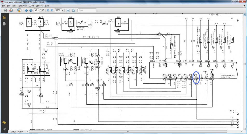
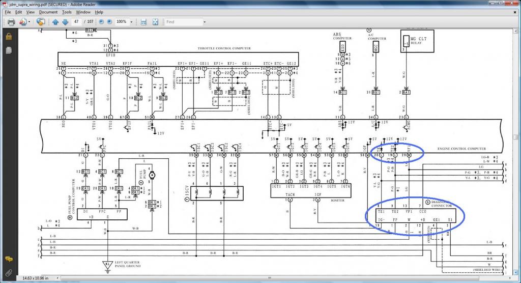
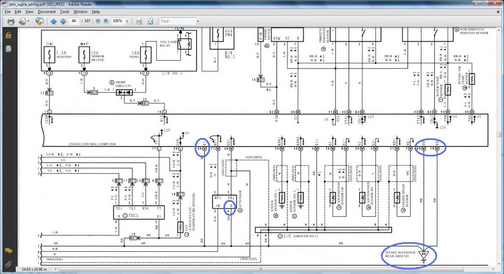
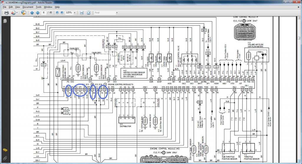
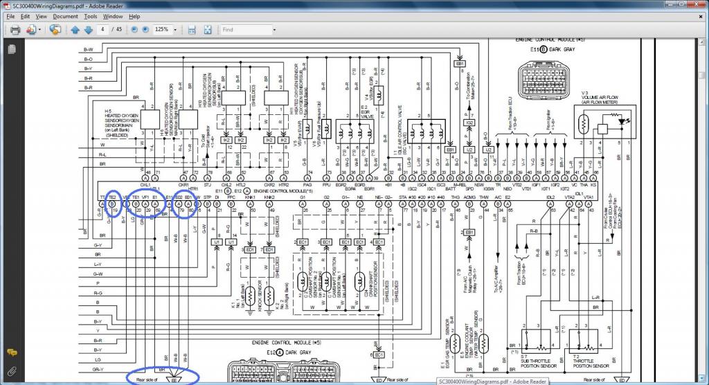
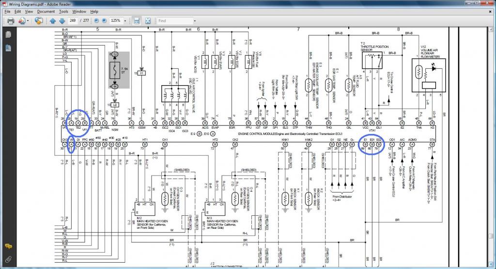
DIAGRAMS TO VERIFY PIN NUMBERING & WHERE THE WIRE GOES
*** KNOCK SENSOR 2 ***
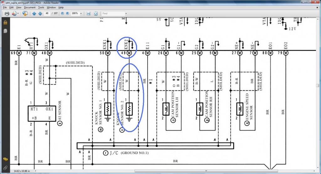
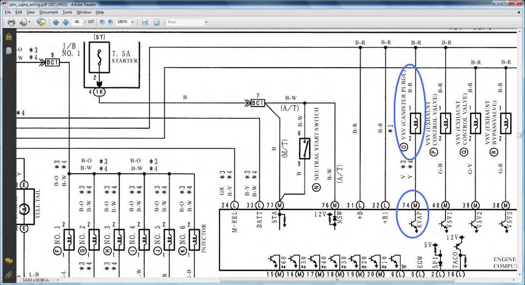
*** VSVEVAP ***
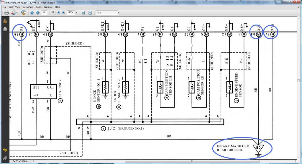
*** REAR INTAKE MANIFOLD GROUND ***
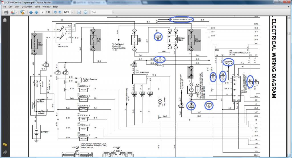
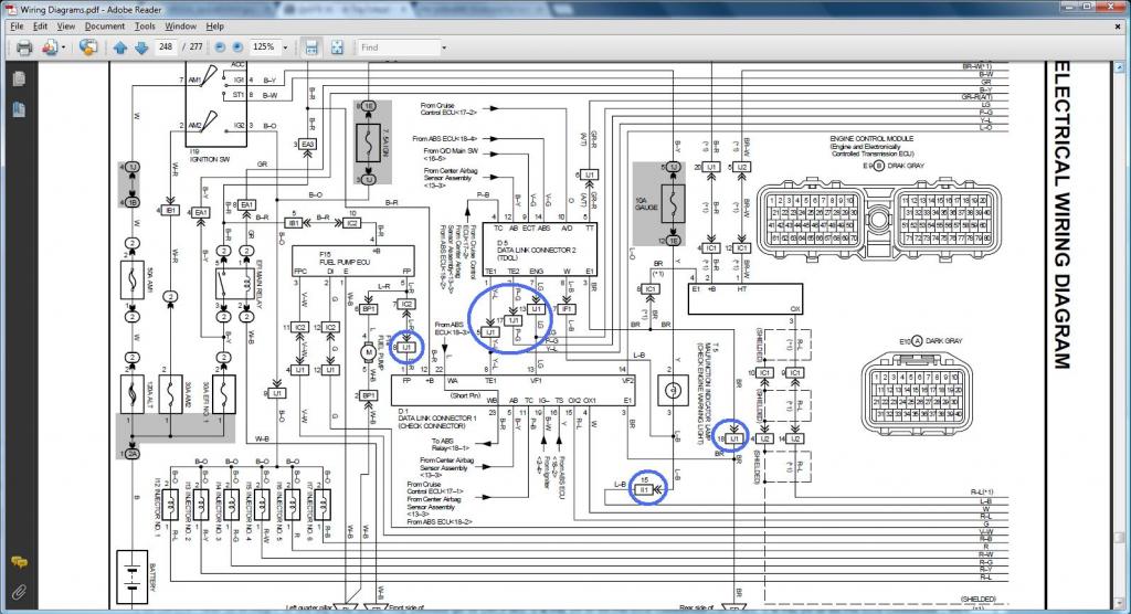
DIAGRAMS TO VERIFY WHERE A WIRE SHOULD GO IN A SC300, SC400, MKIV
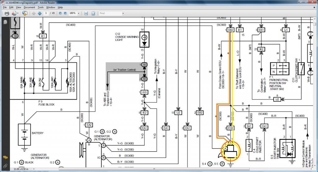
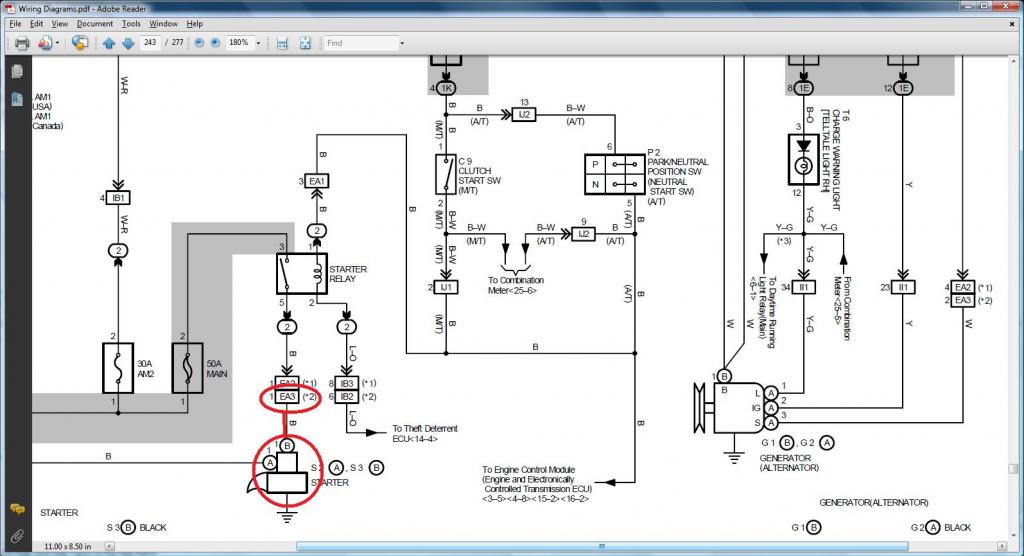
*** STARTER ***
Pin 1 of the Starter (should go to (SC3 EB2-1 , SC4 ED2-2 then EB2-1 , MK4 EA3-1 ))
SC300 - Orange /. SC400 - Yellow
MKIV
*** VSVEVAP ***
We have proven that Pin 1 of VSV1 ( should go to Pin 12 of the Data Link Connector & to ( SC3 IJ1-12 & EB2-1 & Short-4 , SC4 IJ1-12 & EB2-3 , MK4 EA3-3 )) . Since Pin 1 of VSVEVAP goes to Pin 1 of VSV1 , ERGO Pin 1 of VSVEVAP ( should go to Pin 12 of the Data Link Connector & to ( SC3 IJ1-12 & EB2-1 & Short-4 , SC4 IJ1-12 & EB2-3 , MK4 EA3-3 ))
Thus I am not showing those diagrams again.
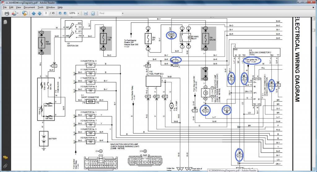
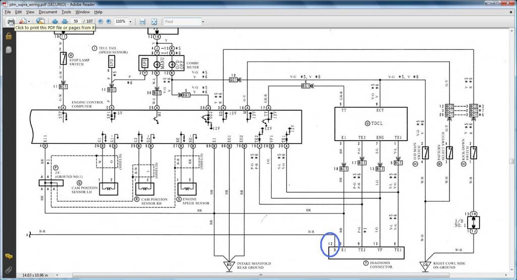
*** DIAGNOSTIC PORT ***
Pin 2 (W) of the Diagnostic Port should go to Pin 6 of the 40 pin ECU Connector & to ( SC3 IK2-9 , SC4 IK2-9 , MK4 II1-15 )
Pin 8 (TE1) of the Diagnostic Port should go to Pin 20 of the 40 pin ECU Connector & to ( SC3 IK1-4 , SC4 IK1-4 , MK4 IJ1-5 )
Pin 9 (TE2) of the Diagnostic Port should go to Pin 19 of the 40 pin ECU Connector & to ( SC3 IK1-2 , SC4 IK1-2 , MK4 IJ1-17 )
Pin 13 (VF1) of the Diagnostic Port should go to Pin 29 of the 80 pin ECU Connector & to ( SC3 IK1-3 , SC4 IK1-3 , MK4 IJ1-13 )
Pin 1 (FP) of the Diagnostic Port (should go to (SC3 IJ1-1 , SC4 IJ1-1 , MK4 IJ1-8 ))
Pin 3 (E1) of the Diagnostic Port (should go to Rear Intake Manifold Ground & to (SC3 Pin 69,79,80 of the 80 pin ECU Connector , SC4 Pin 69,79,80 of the 80 pin ECU Connector , MK4 IJ1-18 ))
Pin 12 (+B) of the Diagnostic Port (should go to (SC3 IJ1-12 & EB2-1 & Short-4 & Pin 2 of O2 Sensor , SC4 IJ1-12 & EB2-3 & Pin 2 of O2 Sensor , MK4 EA3-3 & Pin 31 of 40 pin ECU Connector ))
Read this diagram being on the left of the next diagram so you see continuous flow of current .
Read this diagram being on the right of the previous diagram so you see continuous flow of current
SC300 Read this diagram being on the right of the next diagram so you see continuous flow of current
SC400 Read this diagram being on the right of the next diagram so you see continuous flow of current
MKIV Read this diagram being on the right of the next diagram so you see continuous flow of current
*** KNOCK SENSOR 2 ***

*** VSVEVAP ***

*** REAR INTAKE MANIFOLD GROUND ***

DIAGRAMS TO VERIFY WHERE A WIRE SHOULD GO IN A SC300, SC400, MKIV
*** STARTER ***
Pin 1 of the Starter (should go to (SC3 EB2-1 , SC4 ED2-2 then EB2-1 , MK4 EA3-1 ))
SC300 - Orange /. SC400 - Yellow

MKIV

*** VSVEVAP ***
We have proven that Pin 1 of VSV1 ( should go to Pin 12 of the Data Link Connector & to ( SC3 IJ1-12 & EB2-1 & Short-4 , SC4 IJ1-12 & EB2-3 , MK4 EA3-3 )) . Since Pin 1 of VSVEVAP goes to Pin 1 of VSV1 , ERGO Pin 1 of VSVEVAP ( should go to Pin 12 of the Data Link Connector & to ( SC3 IJ1-12 & EB2-1 & Short-4 , SC4 IJ1-12 & EB2-3 , MK4 EA3-3 ))
Thus I am not showing those diagrams again.
*** DIAGNOSTIC PORT ***
Pin 2 (W) of the Diagnostic Port should go to Pin 6 of the 40 pin ECU Connector & to ( SC3 IK2-9 , SC4 IK2-9 , MK4 II1-15 )
Pin 8 (TE1) of the Diagnostic Port should go to Pin 20 of the 40 pin ECU Connector & to ( SC3 IK1-4 , SC4 IK1-4 , MK4 IJ1-5 )
Pin 9 (TE2) of the Diagnostic Port should go to Pin 19 of the 40 pin ECU Connector & to ( SC3 IK1-2 , SC4 IK1-2 , MK4 IJ1-17 )
Pin 13 (VF1) of the Diagnostic Port should go to Pin 29 of the 80 pin ECU Connector & to ( SC3 IK1-3 , SC4 IK1-3 , MK4 IJ1-13 )
Pin 1 (FP) of the Diagnostic Port (should go to (SC3 IJ1-1 , SC4 IJ1-1 , MK4 IJ1-8 ))
Pin 3 (E1) of the Diagnostic Port (should go to Rear Intake Manifold Ground & to (SC3 Pin 69,79,80 of the 80 pin ECU Connector , SC4 Pin 69,79,80 of the 80 pin ECU Connector , MK4 IJ1-18 ))
Pin 12 (+B) of the Diagnostic Port (should go to (SC3 IJ1-12 & EB2-1 & Short-4 & Pin 2 of O2 Sensor , SC4 IJ1-12 & EB2-3 & Pin 2 of O2 Sensor , MK4 EA3-3 & Pin 31 of 40 pin ECU Connector ))
Read this diagram being on the left of the next diagram so you see continuous flow of current .


Read this diagram being on the right of the previous diagram so you see continuous flow of current

SC300 Read this diagram being on the right of the next diagram so you see continuous flow of current


SC400 Read this diagram being on the right of the next diagram so you see continuous flow of current


MKIV Read this diagram being on the right of the next diagram so you see continuous flow of current


Last edited by gerrb; 02-01-14 at 05:26 AM.
01-31-14, 04:40 PM
#49
Let us work on the plugs for the auto transmission . You either keep them if your swap will be using an auto transmission , remove plugs and wires if you will be using a manual transmission OR keep the wires so you can re-use them for something else in the future.
The INFO you need so you can do THE DRILL
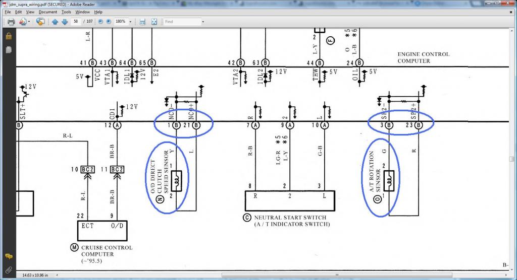
1) O/D Direct Clutch Speed Sensor (O/D)
Pin 1 of O/D goes to Pin 1 of 80 pin ECU Connector
Pin 2 of O/D goes to Pin 21 of 80 pin ECU Connector
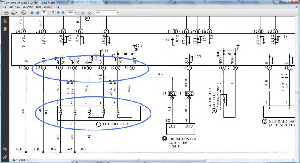
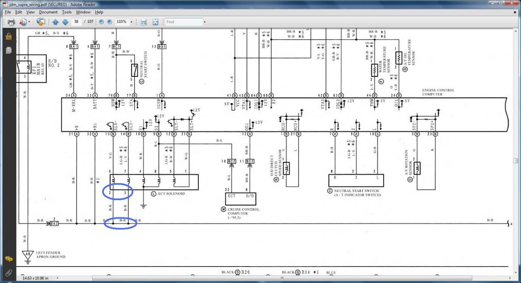
2) Transmission Solenoid (ECT Solenoid)
Pin 1 of Transmission Solenoid goes to Pin 31 of 80 pin ECU Connector
Pin 2 of Transmission Solenoid goes to Pin 3 of Plug E of the Big Aristo Plug (should go to (Pin 12 of the Data Link Connector & to ( SC3 IJ1-12 & EB2-1 & Short-4 , SC4 IJ1-12 & EB2-3 , MK4 EA3-3 )))
Pin 3 of Transmission Solenoid goes to Pin 3 of Plug E of the Big Aristo Plug (should go to (Pin 12 of the Data Link Connector & to ( SC3 IJ1-12 & EB2-1 & Short-4 , SC4 IJ1-12 & EB2-3 , MK4 EA3-3 )))
Pin 4 of Transmission Solenoid goes to Pin 10 of 80 pin ECU Connector
Pin 5 of Transmission Solenoid goes to Pin 12 of 80 pin ECU Connector
Pin 6 of Transmission Solenoid goes to Pin 13 of 80 pin ECU Connector
Pin 7 of Transmission Solenoid goes to Pin 14 of 80 pin ECU Connector
Pin 8 of Transmission Solenoid goes to Pin 9 of 80 pin ECU Connector
3) A/T Rotation Sensor (Speed Sensor 2)
Pin 1 of A/T Rotation Sensor goes to Pin 23 of 80 pin ECU Connector
Pin 2 of A/T Rotation Sensor goes to Pin 3 of 80 pin ECU Connector
4) Speed Sensor 1
Pin 1 of Speed Sensor 1 goes to Pin 14 of Plug F of the Big Aristo Plug (Remove from Aristo plug and needs to go to a body plug)
Pin 2 of Speed Sensor 1 goes to Pin 3 of Plug F of the Big Aristo Plug (Remove from Aristo plug and needs to go to a body plug)
Pin 3 of Speed Sensor 1 goes to Pin 2 of Plug F of the Big Aristo Plug (Remove from Aristo plug and needs to go to a body plug)
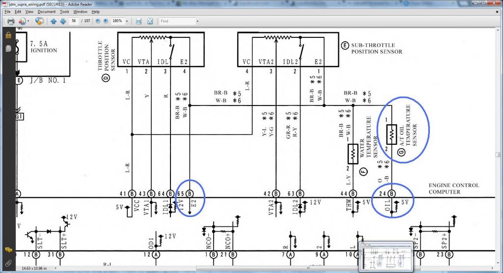
5) A/T Fluid Temp Sensor
Pin 1 of A/T Fluid Temp Sensor goes to Pin 65 of 80 pin ECU Connector
Pin 2 of A/T Fluid Temp Sensor goes to Pin 24 of 80 pin ECU Connector
6) A/T Indicator Switch
Pin 2 of A/T Indicator Switch goes to Pin 9 of Plug E of the Big Aristo Plug (should go to Pin 9 of the 40 pin ECU Connector & to ( SC3 IK1-16 , SC4 IK1-16 , MK4 II1-17 ))
Pin 3 of A/T Indicator Switch goes to Pin 10 of Plug E of the Big Aristo Plug (should go to Pin 10 of the 40 pin ECU Connector & to ( SC3 IK1-17 , SC4 IK1-17 , MK4 II1-27 ))
Pin 4 of A/T Indicator Switch goes to Pin 14 of Plug E of the Big Aristo Plug (should go to ( SC3 IJ1-10 , SC4 IJ1-10 , MK4 II1-23 ))
Pin 5 of A/T Indicator Switch goes to Pin 12 of Plug E of the Big Aristo Plug
Pin 6 of A/T Indicator Switch goes to Pin 5 of Plug E of the Big Aristo Plug
Pin 7 of A/T Indicator Switch goes to Pin 4 of Plug E of the Big Aristo Plug (should go to ( SC3 IK1-12 , SC4 IK1-12 , MK4 II1-7 ))
Pin 8 of A/T Indicator Switch goes to Pin 13 of Plug E of the Big Aristo Plug (should go to Pin 7 of the 40 pin ECU Connector & to ( SC3 IK1-11 , SC4 IK1-11 , MK4 II1-36 ))
Pin 9 of A/T Indicator Switch goes to Pin 11 of Plug E of the Big Aristo Plug (should go to ( SC3 IK1-14 , SC4 IK1-14 , MK4 II1-18 ))
Pin 10 of A/T Indicator Switch goes to Pin 8 of Plug E of the Big Aristo Plug (should go to ( SC3 IK1-13 , SC4 IK1-13 , MK4 II1-1 ))
Guys , time to do THE DRILL .

The INFO you need so you can do THE DRILL
1) O/D Direct Clutch Speed Sensor (O/D)
Pin 1 of O/D goes to Pin 1 of 80 pin ECU Connector
Pin 2 of O/D goes to Pin 21 of 80 pin ECU Connector
2) Transmission Solenoid (ECT Solenoid)
Pin 1 of Transmission Solenoid goes to Pin 31 of 80 pin ECU Connector
Pin 2 of Transmission Solenoid goes to Pin 3 of Plug E of the Big Aristo Plug (should go to (Pin 12 of the Data Link Connector & to ( SC3 IJ1-12 & EB2-1 & Short-4 , SC4 IJ1-12 & EB2-3 , MK4 EA3-3 )))
Pin 3 of Transmission Solenoid goes to Pin 3 of Plug E of the Big Aristo Plug (should go to (Pin 12 of the Data Link Connector & to ( SC3 IJ1-12 & EB2-1 & Short-4 , SC4 IJ1-12 & EB2-3 , MK4 EA3-3 )))
Pin 4 of Transmission Solenoid goes to Pin 10 of 80 pin ECU Connector
Pin 5 of Transmission Solenoid goes to Pin 12 of 80 pin ECU Connector
Pin 6 of Transmission Solenoid goes to Pin 13 of 80 pin ECU Connector
Pin 7 of Transmission Solenoid goes to Pin 14 of 80 pin ECU Connector
Pin 8 of Transmission Solenoid goes to Pin 9 of 80 pin ECU Connector
3) A/T Rotation Sensor (Speed Sensor 2)
Pin 1 of A/T Rotation Sensor goes to Pin 23 of 80 pin ECU Connector
Pin 2 of A/T Rotation Sensor goes to Pin 3 of 80 pin ECU Connector
4) Speed Sensor 1
Pin 1 of Speed Sensor 1 goes to Pin 14 of Plug F of the Big Aristo Plug (Remove from Aristo plug and needs to go to a body plug)
Pin 2 of Speed Sensor 1 goes to Pin 3 of Plug F of the Big Aristo Plug (Remove from Aristo plug and needs to go to a body plug)
Pin 3 of Speed Sensor 1 goes to Pin 2 of Plug F of the Big Aristo Plug (Remove from Aristo plug and needs to go to a body plug)
5) A/T Fluid Temp Sensor
Pin 1 of A/T Fluid Temp Sensor goes to Pin 65 of 80 pin ECU Connector
Pin 2 of A/T Fluid Temp Sensor goes to Pin 24 of 80 pin ECU Connector
6) A/T Indicator Switch
Pin 2 of A/T Indicator Switch goes to Pin 9 of Plug E of the Big Aristo Plug (should go to Pin 9 of the 40 pin ECU Connector & to ( SC3 IK1-16 , SC4 IK1-16 , MK4 II1-17 ))
Pin 3 of A/T Indicator Switch goes to Pin 10 of Plug E of the Big Aristo Plug (should go to Pin 10 of the 40 pin ECU Connector & to ( SC3 IK1-17 , SC4 IK1-17 , MK4 II1-27 ))
Pin 4 of A/T Indicator Switch goes to Pin 14 of Plug E of the Big Aristo Plug (should go to ( SC3 IJ1-10 , SC4 IJ1-10 , MK4 II1-23 ))
Pin 5 of A/T Indicator Switch goes to Pin 12 of Plug E of the Big Aristo Plug
Pin 6 of A/T Indicator Switch goes to Pin 5 of Plug E of the Big Aristo Plug
Pin 7 of A/T Indicator Switch goes to Pin 4 of Plug E of the Big Aristo Plug (should go to ( SC3 IK1-12 , SC4 IK1-12 , MK4 II1-7 ))
Pin 8 of A/T Indicator Switch goes to Pin 13 of Plug E of the Big Aristo Plug (should go to Pin 7 of the 40 pin ECU Connector & to ( SC3 IK1-11 , SC4 IK1-11 , MK4 II1-36 ))
Pin 9 of A/T Indicator Switch goes to Pin 11 of Plug E of the Big Aristo Plug (should go to ( SC3 IK1-14 , SC4 IK1-14 , MK4 II1-18 ))
Pin 10 of A/T Indicator Switch goes to Pin 8 of Plug E of the Big Aristo Plug (should go to ( SC3 IK1-13 , SC4 IK1-13 , MK4 II1-1 ))
Guys , time to do THE DRILL .
Last edited by gerrb; 02-01-14 at 05:26 AM.
01-31-14, 04:46 PM
#50
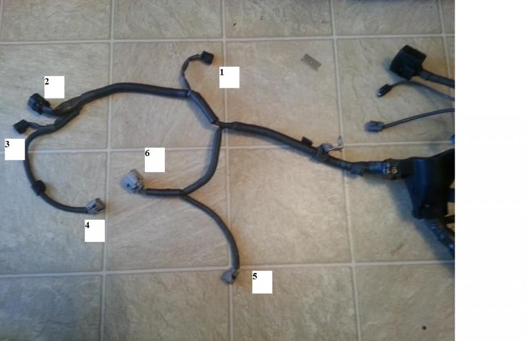
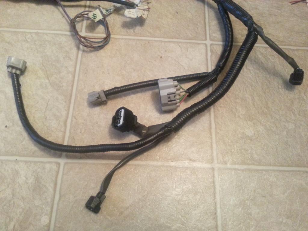
On Aaron's harness, started taking out the auto transmission plugs since he will be on an R154 . Here , I am taking out the wires of the A/T shifter plug. 3 of those wires are T'ed and need to be cut on the T and leave the pins on the Big Gray Aristo plug for now.
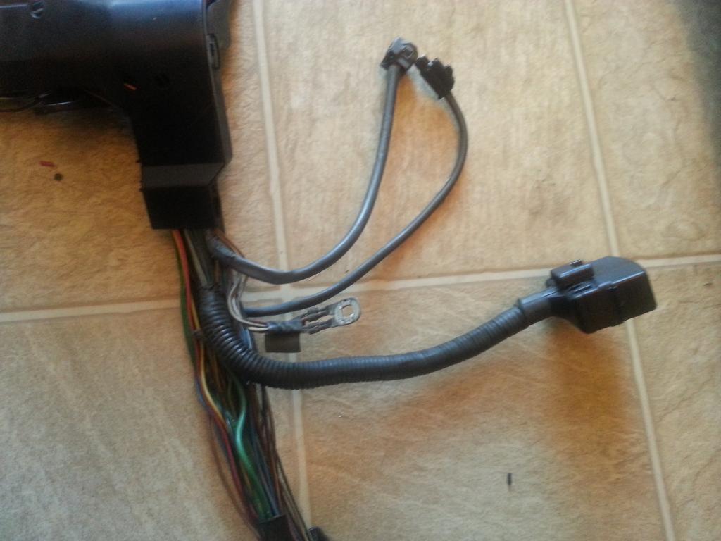
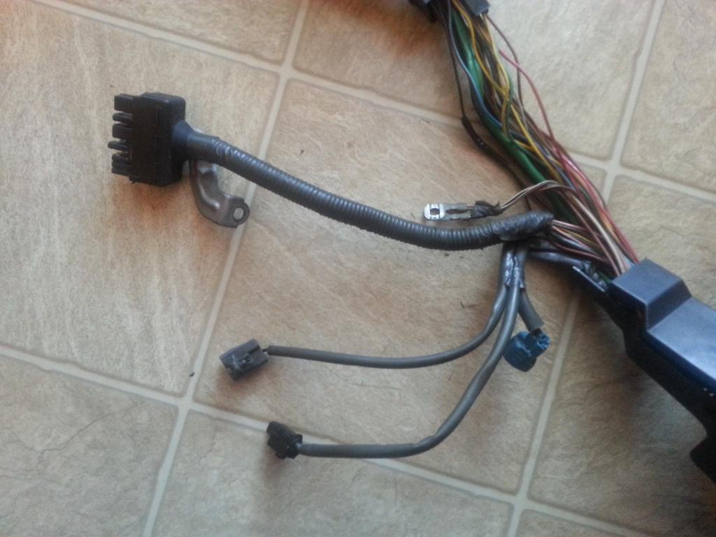
A/T shifter plug removed
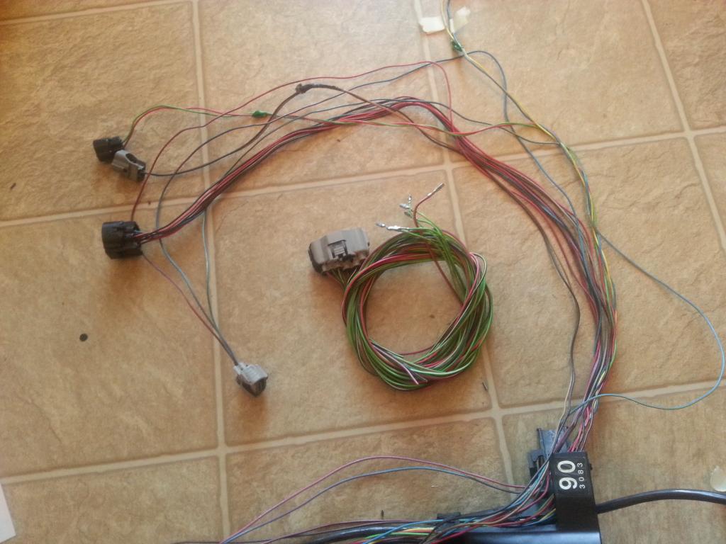
This is what is left on that area for Aaron's harness who is on R154. Am sure you know by now , am a sucker of extra wires so I kept a couple of them there and besides you will have to wire a plug to your manual transmission for a switch (Hint : back up light ) . Make sure you label all extra wires end to end so you know which is which.
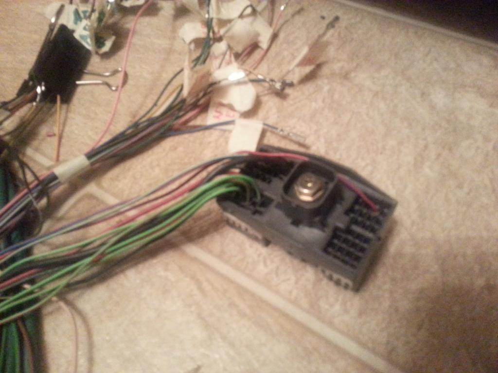
At this point , basically nothing left on the Big Gray Aristo Plug. Those are pins / wires that have Ts on other plugs. The only one without is that big wire that goes to the starter. But still all those wires will have to go to other plugs later so I am leaving them there for now

Last edited by gerrb; 02-01-14 at 05:27 AM.
01-31-14, 04:48 PM
#51
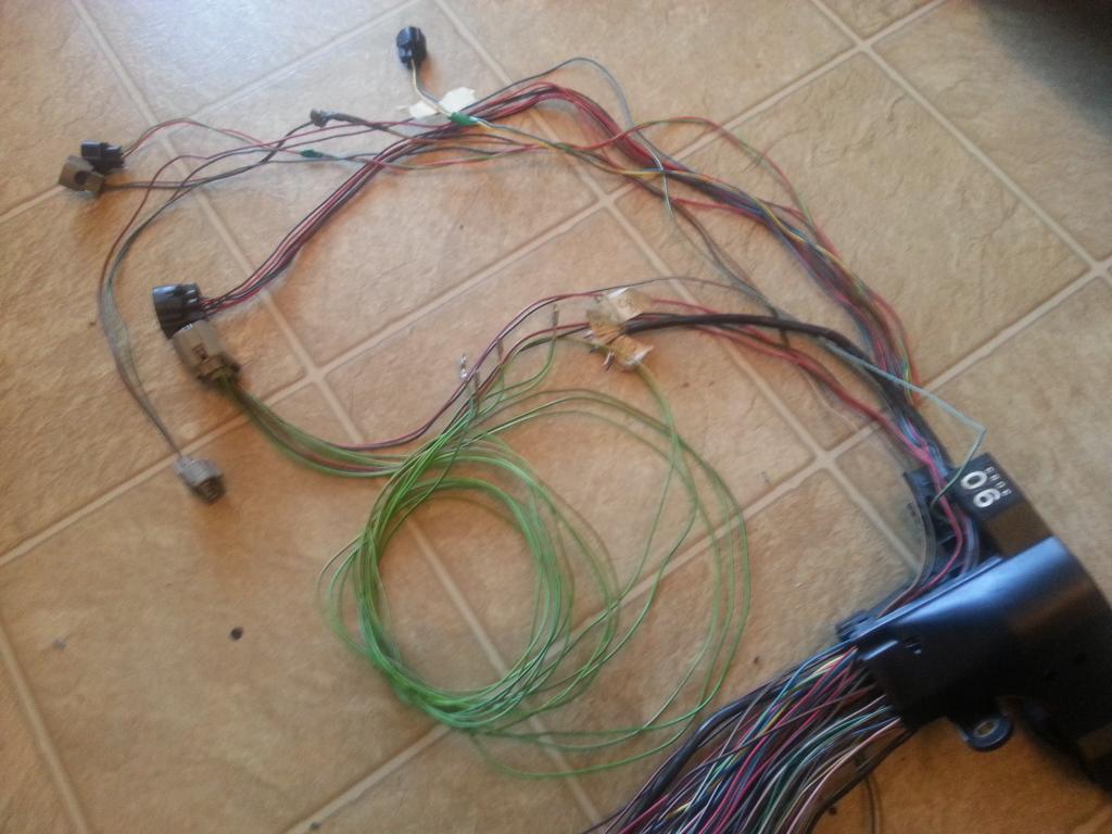
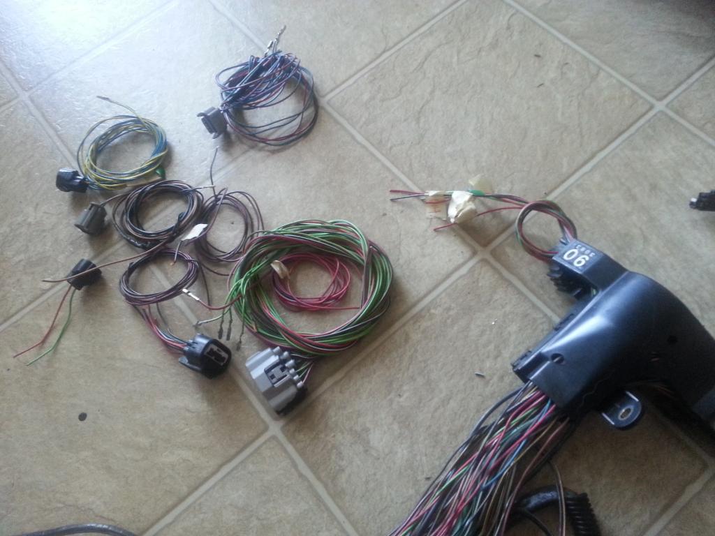
I kept the auto transmission plugs for the Red Mamba 2 harness .
I have 12 extra wires plus a +Voltage and ground wires which I can use for different sensors in the future on this area of the harness.
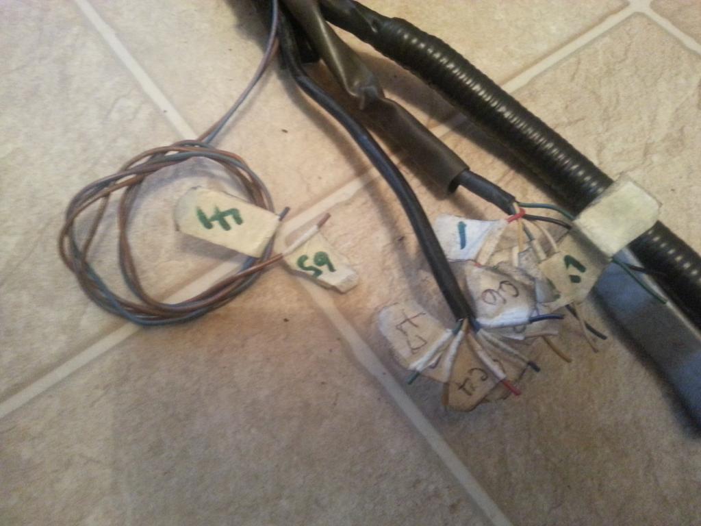
The Big Aristo Gray Plug has zero pins and wires now as you can see it on the picture below. I have organized all wires like which one are for the Diagnostic port , which ones are for the auto transmissions , which are extra wires and so on . When I do the merging of the Aristo 2jzgte harness with the SC300 harness , I know exactly where the wires will go. Good Labeling is the secret !
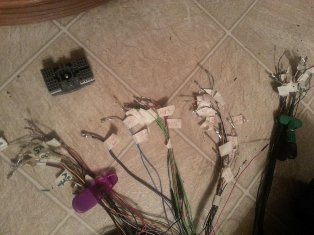

Last edited by gerrb; 02-01-14 at 05:28 AM.
01-31-14, 04:48 PM
#52
Let us update our CHART
80 PIN ECU CONNECTOR
1 <--> Pin 1 of O/D Direct Clutch Speed Sensor CHECKED
2
3 <--> Pin 2 of A/T Rotation Sensor (Speed Sensor 2) CHECKED
7 <--> Pin 2 of the Crankshaft Position Sensor CHECKED
9 <--> Pin 8 of Transmission Solenoid CHECKED
10 <--> Pin 4 of Transmission Solenoid CHECKED
12 <--> Pin 5 of Transmission Solenoid CHECKED
13 <--> Pin 6 of Transmission Solenoid CHECKED
14 <--> Pin 7 of Transmission Solenoid CHECKED
20 <--> Pin 1 of the Injector No. 1 CHECKED
21 <--> Pin 2 of O/D Direct Clutch Speed Sensor CHECKED
23 <--> Pin 1 of A/T Rotation Speed Sensor (Speed Sensor 2) CHECKED
24 <--> Pin 2 of the A/T Fluid Temp Sensor CHECKED
27 <--> Pin 1 of the Crankshaft Position Sensor CHECKED
30
31 <--> Pin 1 of Transmission Solenoid CHECKED
38 <--> Pin 2 of the VSV3 CHECKED
39 <--> Pin 2 of the VSV2 CHECKED
40 <--> Pin 2 of the VSV1 CHECKED
41 <--> Pin 1 of the TPS <--> Pin 4 of the Sub-TPS CHECKED
42 <--> Pin 3 of the Sub-TPS CHECKED
43 <--> Pin 2 of the TPS CHECKED
44 <--> Pin 2 of the Water Temperature Sensor CHECKED
48 <--> Pin 3 of the O2 Sensor CHECKED
49 <--> Pin 1 of the Knock Sensor 1 CHECKED
50 <--> Pin 1 of the Knock Sensor 1 CHECKED
51
52 <--> Pin 7 of the 12 pin Igniter Connector CHECKED
53 <--> Pin 8 of the 12 pin igniter Connector CHECKED
54 <--> Pin 9 of the 12 pin igniter Connector CHECKED
55 <--> Pin 3 of the 12 pin igniter Connector CHECKED
56 <--> Pin 2 of the 12 pin Igniter Connector CHECKED
57 <--> Pin 1 of the 12 pin Igniter Connector CHECKED
58 <--> Pin 3 of the 4 pin Igniter Connector CHECKED
59
60 <--> Pin 2 of the VSVPMC CHECKED
63 <--> Pin 2 of the Sub-TPS CHECKED
64 <--> Pin 3 of the TPS CHECKED
65 <--> Pin 1 of the Water Temperature Sensor <--> Pin 4 of the TPS <--> Pin 1 of the Sub-TPS <--> Pin 1 of A/T Fluid Temp Sensor CHECKED
69 <--> Rear Intake Manifold Ground CHECKED
70
71 <--> Pin 1 of the O2 Sensor CHECKED
74 <--> Pin 2 of the VSVEVAP CHECKED
79 <--> Rear Intake Manifold Ground CHECKED
80 <--> Rear Intake Manifold Ground CHECKED
4 PIN IGNITER CONNECTOR
1 <--> Pin 12 of Plug F of Aristo plug <--> ( Pin 19 of the Data Link Connector <--> ( SC3 IK1-8 , SC4 IK1-8 , MK4 ))
2 <--> Pin 6 of Plug F of Aristo plug <--> Pin 1 of the Noise Filter <--> ( SC3 IJ1-7 , SC4 EB2-2 , MK4 IJ1-1 or IJ1-9 )
3 <--> Pin 58 of the 80 pin ECU connector CHECKED
4 <--> Ground Connector on the Front Side of Intake Manifold <--> Pin 2 of the Noise filter Connector CHECKED
12 PIN IGNITER CONNECTOR
1 <--> Pin 57 of the 80 pin ECU connector CHECKED
2 <--> Pin 56 of the 80 pin ECU connector CHECKED
3 <--> Pin 55 of the 80 pin ECU connector CHECKED
4 <--> Pin 2 of the Ignition Coil Connector 3 CHECKED
5 <--> Pin 2 of the Ignition Coil Connector 2 CHECKED
6 <--> Pin 2 of the Ignition Coil Connector 1 CHECKED
7 <--> Pin 52 of the 80 pin ECU connector CHECKED
8 <--> Pin 53 of the 80 pin ECU connector CHECKED
9 <--> Pin 54 of the 80 pin ECU connector CHECKED
10 <--> Pin 2 of the Ignition Coil Connector 4 CHECKED
11 <--> Pin 2 of the Ignition Coil Connector 5 CHECKED
12 <--> Pin 2 of the Ignition Coil Connector 6 CHECKED
AC COMPRESSOR PLUG
1 <--> Pin 1 of Plug C of the Aristo Plug (should go to (SC3 EB1-7 & II1-1 , SC4 EB1-7 & II1-1 , MK4 II1-26 ))
2 <--> Pin 2 of Plug C of the Aristo Plug (should go to (SC3 II1-4 , SC4 II1-4 , MK4 II1-20 ))
4 <--> Pin 5 of Plug C of the Aristo Plug (should go to (SC3 EB1-1 , SC4 EB1-1 , MK4 EA1-1 & II1-10 ))
A/T FLUID TEMP SENSOR
1 <--> Pin 65 of 80 pin ECU Connector CHECKED
2 <--> Pin 24 of 80 pin ECU Connector CHECKED
A/T ROTATION SPEED SENSOR (Speed Sensor 2)
1 <--> Pin 23 of 80 pin ECU Connector CHECKED
2 <--> Pin 3 of 80 pin ECU Connector CHECKED
A/T INDICATOR SWITCH
2 <--> Pin 9 of Plug E of the Big Aristo Plug (should go to Pin 9 of the 40 pin ECU Connector & to ( SC3 IK1-16 , SC4 IK1-16 , MK4 II1-17 ))
3 <--> Pin 10 of Plug E of the Big Aristo Plug (should go to Pin 10 of the 40 pin ECU Connector & to ( SC3 IK1-17 , SC4 IK1-17 , MK4 II1-27 ))
4 <--> Pin 14 of Plug E of the Big Aristo Plug (should go to ( SC3 IJ1-10 , SC4 IJ1-10 , MK4 II1-23 ))
5 <--> Pin 12 of Plug E of the Big Aristo Plug (should go to (SC3 IK2-23, SC4 IK2-23, MK4 IJ2-9))
6 <--> Pin 5 of Plug E of the Big Aristo Plug (should go to (SC3 IJ1-6, SC4 IJ1-6, MK4 IJ2-13))
7 <--> Pin 4 of Plug E of the Big Aristo Plug (should go to ( SC3 IK1-12 , SC4 IK1-12 , MK4 II1-7 ))
8 <--> Pin 13 of Plug E of the Big Aristo Plug (should go to Pin 7 of the 40 pin ECU Connector & to ( SC3 IK1-11 , SC4 IK1-11 , MK4 II1-36 ))
9 <--> Pin 11 of Plug E of the Big Aristo Plug (should go to ( SC3 IK1-14 , SC4 IK1-14 , MK4 II1-18 ))
10 <--> Pin 8 of Plug E of the Big Aristo Plug (should go to ( SC3 IK1-13 , SC4 IK1-13 , MK4 II1-1 ))
CRANKSHAFT POSITION SENSOR
1 <--> Pin 27 of the 80 pin ECU Connector CHECKED
2 <--> Pin 7 of the 80 pin ECU Connector CHECKED
DIAGNOSTIC PORT
1 (FP) <--> Pin 15 of Plug C of the Big Gray Aristo Plug (should go to (SC3 IJ1-1 , SC4 IJ1-1 , MK4 IJ1-8 ))
2 (W) <--> Pin 2 of Plug E of the Big Gray Aristo Plug (should go to Pin 6 of the 40 pin ECU Connector & to (SC3 IK2-9 , SC4 IK2-9 , MK4 II1-15 ))
3 (E1) <--> Pin 11 of Plug F of the Big Gray Aristo Plug (should go to Rear Intake Manifold Ground & to (SC3 Pin 69,79,80 of the 80 pin ECU Connector , SC4 IK1-1 & Pin 69,79,80 of the 80 pin ECU Connector , MK4 IJ1-18 ))
4 (OX1)<--> Pin 48 of the 80 pin ECU Connector
5 (AB) <--> Pin 4 of Plug D of the Big Gray Aristo Plug
6 (OP1)<--> Pin 10 of Plug D of the Big Gray Aristo Plug
7 (CCo)<--> Pin 8 of Plug D of the Big Gray Aristo Plug
8 (TE1) <--> Pin 4 of Plug F of the Big Gray Aristo Plug(should go to Pin 20 of the 40 pin ECU Connector & to ( SC3 IK1-4 , SC4 IK1-4 , MK4 IJ1-5 ))
9 (TE2) <--> Pin 7 of Plug E of the Big Gray Aristo Plug (should go to Pin 19 of the 40 pin ECU Connector & to ( SC3 IK1-2 , SC4 IK1-2 , MK4 IJ1-17 ))
11 (TC)<--> Pin 6 of Plug E of the Big Gray Aristo Plug
12 (+B)<--> Pin 3 of Plug E of the Big Gray Aristo Plug (should go to (SC3 IJ1-12 & EB2-1 & Short-4 & Pin 2 of O2 Sensor , SC4 IJ1-12 & EB2-3 & Pin 2 of O2 Sensor , MK4 EA3-3 & Pin 31 of 40 pin ECU Connector ))
13 (VF1)<-->Pin 10 of Plug F of the Big Gray Aristo Plug (should go to Pin 29 of the 80 pin ECU Connector & to ( SC3 IK1-3 , SC4 IK1-3 , MK4 IJ1-13 ))
16 (TS)<--> Pin 5 of Plug F of the Big Gray Aristo Plug
18 (TEM)<--> Pin 5 of Plug D of the Big Gray Aristo Plug
19 (IG-) <--> Pin 1 of the 4 pin Igniter Connector
22 (WA) <--> PIn 7 of Plug D of the Big Gray Aristo Plug
23 (WB) <--> Pin 11 of Plug D of the Big Gray Aristo Plug
GROUND - Front Intake Manifold
1 <--> Pin 2 of Noise Filter <--> Pin 4 of the 4 pin ECU CONNECTOR CHECKED
GROUND - Rear Intake Manifold
1 <--> Pin 69 <---> Pin 79 <--> Pin 80 of the 80 pin ECU Connector CHECKED
IGNITION COIL 1
1 <--> Pin 1 of the Noise Filter <--> Pin 2 of the 4 pin Igniter Connector <--> Pin 1 of Ignition Coil 2,3,4,5,6 <-->( SC3 IJ1-7 , SC4 EB2-2 , MK4 IJ1-1 or IJ1-9 )
2 <--> Pin 6 of the 12 Pin Igniter Connector CHECKED
IGNITION COIL 2
1 <--> Pin 1 of the Noise Filter <--> Pin 2 of the 4 pin Igniter Connector <--> Pin 1 of Ignition Coil 1,3,4,5,6 <-->( SC3 IJ1-7 , SC4 EB2-2 , MK4 IJ1-1 or IJ1-9 )
2 <--> Pin 5 of the 12 Pin Igniter Connector CHECKED
IGNITION COIL 3
1 <--> Pin 1 of the Noise Filter <--> Pin 2 of the 4 pin Igniter Connector <--> Pin 1 of Ignition Coil 1,2,4,5,6 <-->( SC3 IJ1-7 , SC4 EB2-2 , MK4 IJ1-1 or IJ1-9 )
2 <--> Pin 4 of the 12 Pin Igniter Connector CHECKED
IGNITION COIL 4
1 <--> Pin 1 of the Noise Filter <--> Pin 2 of the 4 pin Igniter Connector <--> Pin 1 of Ignition Coil 1,2,3,5,6 <-->( SC3 IJ1-7 , SC4 EB2-2 , MK4 IJ1-1 or IJ1-9 )
2 <--> Pin 10 of the 12 Pin Igniter Connector CHECKED
IGNITION COIL 5
1 <--> Pin 1 of the Noise Filter <--> Pin 2 of the 4 pin Igniter Connector <--> Pin 1 of Ignition Coil 1,2,3,4,6 <-->( SC3 IJ1-7 , SC4 EB2-2 , MK4 IJ1-1 or IJ1-9 )
2 <--> Pin 11 of the 12 Pin Igniter Connector CHECKED
IGNITION COIL 6
1 <--> Pin 1 of the Noise Filter <--> Pin 2 of the 4 pin Igniter Connector <--> Pin 1 of Ignition Coil 1,2,3,4,5 <-->( SC3 IJ1-7 , SC4 EB2-2 , MK4 IJ1-1 or IJ1-9 )
2 <--> Pin 12 of the 12 Pin Igniter Connector CHECKED
INJECTOR NO. 1
1 <--> Pin 20 of the 80 pin ECU Connector
2 <--> (should go to (SC3 IJ1-7 or IJ1-3 & short 3 & short 5 , SC40 EB2-2 , MK4 IJ1-9))
KNOCK SENSOR 1
1 <--> Pin 50 of the 80 pin ECU Connector CHECKED
KNOCK SENSOR 2
1 <--> Pin 49 of the 80 pin ECU Connector CHECKED
NOISE FILTER
1 <--> Pin 2 of the 4 pin Igniter Connector <--> ( SC3 IJ1-7, SC4 EB2-2 , MK4 IJ1-1 or IJ1-9 )
2 <--> Ground Connector on the Front Side of Intake Manifold <--> Pin 4 of the 4 pin Igniter Connector CHECKED
O/D DIRECT CLUTCH SPEED SENSOR (O/D)
1 <--> Pin 1 of 80 pin ECU Connector CHECKED
2 <--> Pin 21 of 80 pin ECU Connector CHECKED
OIL LEVEL SENSOR PLUG
1 <--> Pin 1 of Plug D of Big Gray Aristo Plug (should go to (SC3 IK2-10 , SC4 IK2-10 , MK4 II1-33 ))
2 <--> Pin 7 of Plug F of Big Gray Aristo Plug(should go to ( SC3 / SC4 / MK4 Rear Intake Manifold Ground for all ))
OIL PRESSURE PLUG
1 <--> Pin 8 of Plug F of the Aristo Plug (should go to ( SC3 IK1-20 , SC4 IK1-20 , MK4 II1-25 ))
STARTER
1 <--> Pin 1 of Plug F of Big Gray Aristo Plug (should go to (SC3 EB2-1 , SC4 EB2-1 , MK4 EA3-1 ))
THROTTLE POSITION SENSOR
1 <--> Pin 41 of the 80 pin ECU Connector CHECKED
2 <--> Pin 43 of the 80 pin ECU Connector CHECKED
3 <--> Pin 64 of the 80 pin ECU Connector CHECKED
4 <--> Pin 65 of the 80 pin ECU Connector CHECKED
TRANSMISSION SOLENOID (ECT Solenoid)
1 <--> Pin 31 of 80 pin ECU Connector
2 <--> Pin 3 of Plug E of the Big Aristo Plug (should go to (Pin 12 of the Data Link Connector & to ( SC3 IJ1-12 & EB2-1 & Short-4 , SC4 IJ1-12 & EB2-3 , MK4 EA3-3 )))
3 <--> Pin 3 of Plug E of the Big Aristo Plug (should go to (Pin 12 of the Data Link Connector & to ( SC3 IJ1-12 & EB2-1 & Short-4 , SC4 IJ1-12 & EB2-3 , MK4 EA3-3 )))
4 <--> Pin 10 of 80 pin ECU Connector
5 <--> Pin 12 of 80 pin ECU Connector
6 <--> Pin 13 of 80 pin ECU Connector
7 <--> Pin 14 of 80 pin ECU Connector
8 <--> Pin 9 of 80 pin ECU Connector
WATER TEMPERATURE SENSOR
1 <--> Pin 65 of the 80 pin ECU Connector CHECKED
2 <--> Pin 44 of the 80 pin ECU Connector CHECKED
WATER TEMPERATURE GAUGE SENDER
1 <--> Pin 9 of Plug F of the Big Gray Aristo Plug (should go to SC3 IK1-9 , SC4 IK1-9 & Short-3 , MK4 II1-19 )
The following plugs are necessary only if you are going stock 2jzgte setup
OXYGEN SENSOR (O2)
1 <--> Pin 71 of the 80 pin ECU Connector CHECKED
2 <--> Pin 3 of Plug E of Aristo Plug <-> (Pin 12 of the Data Link Connector <--> ( SC3 IJ1-12 & EB2-1 & Short-4 , SC4 IJ1-12 & EB2-3 , MK4 EA3-3 ))
3 <--> Pin 48 of the 80 pin ECU Connector CHECKED
VSV1 ( Air Intake Control Valve )
1 <--> Pin 2 of the O2 Sensor <--> Pin 1 of the VSV3 <-> (Pin 12 of the Data Link Connector <--> ( SC3 IJ1-12 & EB2-1 & Short-4 , SC4 IJ1-12 & EB2-3 , MK4 EA3-3 ))
2 <--> Pin 40 of the 80 pin ECU Connector CHECKED
VSV2 ( Exhaust Control Valve )
1 <--> Pin 1 of VSV1 , VSV3 , VSVPMC <--> Pin 2 of the O2 Sensor <--> Pin 1 of the VSV3 <-> (Pin 12 of the Data Link Connector <--> ( SC3 IJ1-12 & EB2-1 & Short-4 , SC4 IJ1-12 & EB2-3 , MK4 EA3-3 ))
2 <--> Pin 39 of the 80 pin ECU Connector CHECKED
VSV3( Exhaust Bypass Valve )
1 <--> Pin 2 of the O2 Sensor <-->Pin 1 of the VSV1 <-> (Pin 12 of the Data Link Connector <--> ( SC3 IJ1-12 & EB2-1 & Short-4 , SC4 IJ1-12 & EB2-3 , MK4 EA3-3 ))
2 <--> Pin 38 of the 80 pin ECU Connector CHECKED
VSVEVAP ( Canister Purge )
1 <--> Pin 1 of VSV1 , VSV2 , VSV3 , VSVPMC <--> (Pin 12 of the Data Link Connector <--> ( SC3 IJ1-12 & EB2-1 & Short-4 , SC4 IJ1-12 & EB2-3 , MK4 EA3-3 ))
2 <--> Pin 74 of the 80 pin ECU Connector
VSVPMC ( Waste Gate Valve )
1 <--> Pin 1 of VSV1 , VSV2 , VSV3 <--> Pin 2 of the O2 Sensor <--> Pin 1 of the VSV3 <-> (Pin 12 of the Data Link Connector <--> ( SC3 IJ1-12 & EB2-1 & Short-4 , SC4 IJ1-12 & EB2-3 , MK4 EA3-3 ))
2 <--> Pin 60 of the 80 pin ECU Connector CHECKED
The following plugs maybe kept or deleted depending on your seup
2) Sub-Throttle Position Sensor
1 <--> Pin 65 of the 80 pin ECU Connector CHECKED
2 <--> Pin 63 of the 80 pin ECU Connector CHECKED
3 <--> Pin 42 of the 80 pin ECU Connector CHECKED
4 <--> Pin 41 of the 80 pin ECU Connector CHECKED
The following plugs are usually deleted
Throttle Motor Valve
1 <--> Pin 8 of Plug C of Big Gray Aristo Plug
2 <--> Pin 11 of Plug C of Big Gray Aristo Plug
3 <--> Pin 7 of Plug C of Big Gray Aristo Plug
4 <--> Pin 4 of Plug C of Big Gray Aristo Plug
5 <--> Pin 6 of Plug C of Big Gray Aristo Plug
6 <--> Pin 3 of Plug C of Big Gray Aristo Plug
The following plug definitely will be deleted but its wires go to different body plugs or 40 pin ECU Connector or can be used for future needs
BIG GRAY ARISTO PLUG
PLUG C
1 <--> (SC3 EB1-7 & II1-1 , SC4 EB1-7 & II1-1 , MK4 II1-26 ))
2 <-->(should go to (SC3 II1-4 , SC4 II1-4 , MK4 II1-20 ))
3 <--> Extra Wire for future use CHECKED
4 <--> Extra Wire for future use CHECKED
5 <--> (should go to (SC3 EB1-1 , SC4 EB1-1 , MK4 EA1-1 & II1-10 ))
6 <--> Extra Wire for future use CHECKED
7 <--> Extra Wire for future use CHECKED
8 <--> Extra Wire for future use CHECKED
11 <--> Extra Wire for future use CHECKED
13 <--> Extra Wire for future use CHECKED
15 <--> Pin 1 (FP) of Diagnostic Port goes (should go to (SC3 IJ1-1 , SC4 IJ1-1 , MK4 IJ1-8 ))
PLUG D
1 <--> (should go to (SC3 IK2-10 , SC4 IK2-10 , MK4 II1-33 ))
4 <--> Pin 5 (AB) of Diagnostic Port
5 <--> Pin 18 (TEM) of Diagnostic Port
6 <--> Pin 63 of the 80 pin ECU Connector (Is still needed ????? remains to be seen during the merge process)
7 <--> Pin 22 (WA) of Diagnostic Port
8 <--> Pin 7 (CCo) of Diagnotic Port
9 <--> Extra Wire for future use CHECKED
10<-->Pin 6 (OP1) of Diagnostic Port
11<-->Pin 23 (WB) of Diagnostic Port
PLUG E
2 <--> Pin 2 (W) of Diagnostic Port (should go to Pin 6 of the 40 pin ECU Connector & to (SC3 IK2-9 , SC4 IK2-9 , MK4 II1-15 ))
3 <--> Pin 2 of Oxygen Sensor <--> Pin 2 & Pin 3 of Transmission Solenoid <--> (Pin 12 of the Data Link Connector <--> ( SC3 IJ1-12 & EB2-1 & Short-4 , SC4 IJ1-12 & EB2-3 , MK4 EA3-3 ))
4 <--> Pin 12 (+B) of Diagnostic Port <--> Pin 7 of A/T Indicator Switch (should go to (SC3 IJ1-12 & EB2-1 & Short-4 & Pin 2 of O2 Sensor & IK1-12 , SC4 IJ1-12 & EB2-3 & Pin 2 of O2 Sensor & IK1-12 , MK4 EA3-3 & Pin 31 of 40 pin ECU Connector & II1-7 ))
5 <--> Pin 6 of A/T Indicator Switch
6 <--> Pin 11 (TC) of Diagnostic Port
7 <--> Pin 9 (TE2) of Diagnostic Port (should go to Pin 19 of the 40 pin ECU Connector & to ( SC3 IK1-2 , SC4 IK1-2 , MK4 IJ1-17 ))
8 <--> Pin 10 of A/T Indicator Switch (should go to ( SC3 IK1-13 , SC4 IK1-13 , MK4 II1-1 ))
9 <--> Pin 2 of A/T Indicator Switch (should go to Pin 9 of the 40 pin ECU Connector & to ( SC3 IK1-16 , SC4 IK1-16 , MK4 II1-17 ))
10 <--> Pin 3 of A/T Indicator Switch (should go to Pin 10 of the 40 pin ECU Connector & to ( SC3 IK1-17 , SC4 IK1-17 , MK4 II1-27 ))
11 <--> Pin 9 of A/T Indicator Switch (should go to ( SC3 IK1-14 , SC4 IK1-14 , MK4 II1-18 ))
12 <--> Pin 5 of A/T Indicator Switch
13 <--> Pin 8 of A/T Indicator Switch (should go to Pin 7 of the 40 pin ECU Connector & to ( SC3 IK1-11 , SC4 IK1-11 , MK4 II1-36 ))
14 <--> Pin 4 of A/T Indicator Switch (should go to ( SC3 IJ1-10 , SC4 IJ1-10 , MK4 II1-23 ))
PLUG F
4 <--> Pin 8 (TE1) of Diagnostic Port ((should go to Pin 20 of the 40 pin ECU Connector & to ( SC3 IK1-4 , SC4 IK1-4 , MK4 IJ1-5 ))
5 <--> Pin 16 (TS) of Diagnostic Port
6 <--> Pin 1 of the Noise Filter <--> ( SC3 IJ1-7 , SC4 EB2-2 , MK4 IJ1-1 or IJ1-9 )
7 <--> (should go to ( SC3 / SC4 / MK4 Rear Intake Manifold Ground for all ))
8 <--> (should go to ( SC3 IK1-20 , SC4 IK1-20 , MK4 II1-25 ))
9 <--> Pin 1 of the Water Temperature Gauge Sender <--> ( SC3 IK1-9 , SC4 IK1-9 & Short-3 , MK4 II1-19 )
10<--> Pin 13 (VF1) of Diagnostic Port (should go to Pin 29 of the 80 pin ECU Connector & to ( SC3 IK1-3 , SC4 IK1-3 , MK4 IJ1-13 ))
11<--> Pin 3 (E1) of Diagnostic Port (should go to Rear Intake Manifold Ground & to (SC3 Pin 69,79,80 of the 80 pin ECU Connector , SC4 IK1-1 & Pin 69,79,80 of the 80 pin ECU Connector , MK4 IJ1-18 ))
12 <--> ( Pin 19 of the Data Link Connector & to ( SC3 IK1-8 , SC4 IK1-8 , MK4 ))
Last edited by gerrb; 03-25-15 at 04:25 PM.
01-31-14, 04:50 PM
#53
DIAGRAMS TO VERIFY PIN NUMBERING & WHERE THE WIRE GOES
*** O/D Direct Clutch Speed Sensor (O/D) & A/T Rotation Sensor (Speed Sensor 2) ***
*** A/T Fluid Temp Sensor ***
*** Transmission Solenoid (ECT Solenoid) ***
*** O/D Direct Clutch Speed Sensor (O/D) & A/T Rotation Sensor (Speed Sensor 2) ***

*** A/T Fluid Temp Sensor ***

*** Transmission Solenoid (ECT Solenoid) ***

Last edited by gerrb; 02-01-14 at 05:29 AM.
01-31-14, 04:53 PM
#54
DIAGRAMS TO VERIFY WHERE A WIRE SHOULD GO IN A SC300, SC400, MKIV
*** Transmission Solenoid (ECT Solenoid) ***
Pin 2 of Transmission Solenoid (should go to (Pin 12 of the Data Link Connector & to ( SC3 IJ1-12 & EB2-1 & Short-4 , SC4 IJ1-12 & EB2-3 , MK4 EA3-3 )))
Pin 3 of Transmission Solenoid (should go to (Pin 12 of the Data Link Connector & to ( SC3 IJ1-12 & EB2-1 & Short-4 , SC4 IJ1-12 & EB2-3 , MK4 EA3-3 )))
Read this diagram being on the right of the next diagram so you see continuous
*** A/T Indicator Switch ***
Pin 2 of A/T Indicator Switch (should go to Pin 9 of the 40 pin ECU Connector & to ( SC3 IK1-16 , SC4 IK1-16 , MK4 II1-17 ))
Pin 3 of A/T Indicator Switch (should go to Pin 10 of the 40 pin ECU Connector & to ( SC3 IK1-17 , SC4 IK1-17 , MK4 II1-27 ))
Pin 4 of A/T Indicator Switch (should go to ( SC3 IJ1-10 , SC4 IJ1-10 , MK4 II1-23 ))
Pin 5 of A/T Indicator Switch (should go to (SC3 IK2-23, SC4 IK2-23, MK4 IJ2-9))
Pin 6 of A/T Indicator Switch (should go to (SC3 IJ1-6, SC4 IJ1-6, MK4 IJ2-13))
Pin 7 of A/T Indicator Switch (should go to ( SC3 IK1-12 , SC4 IK1-12 , MK4 II1-7 ))
Pin 8 of A/T Indicator Switch (should go to Pin 7 of the 40 pin ECU Connector & to( SC3 IK1-11 , SC4 IK1-11 , MK4 II1-36 ))
Pin 9 of A/T Indicator Switch (should go to ( SC3 IK1-14 , SC4 IK1-14 , MK4 II1-18 ))
Pin 10 of A/T Indicator Switch (should go to ( SC3 IK1-13 , SC4 IK1-13 , MK4 II1-1 ))
I want you to pay attention on the next diagram for the 2jzgte Auto Transmission indicator switch numbering. I have encircled those numbers. This is what we are going to use. When I post the indicator switch of the SC300 / SC400 later , they have a different numbering but don't worry about it. It's this numbering on the next diagram that matters.
Pin 7 - Park
Pin 8 - Reverse
Pin 10- Neutral
Pin 9 - Drive
Pin 2 - 2nd Gear
Pin 3 - Low / 1st Gear
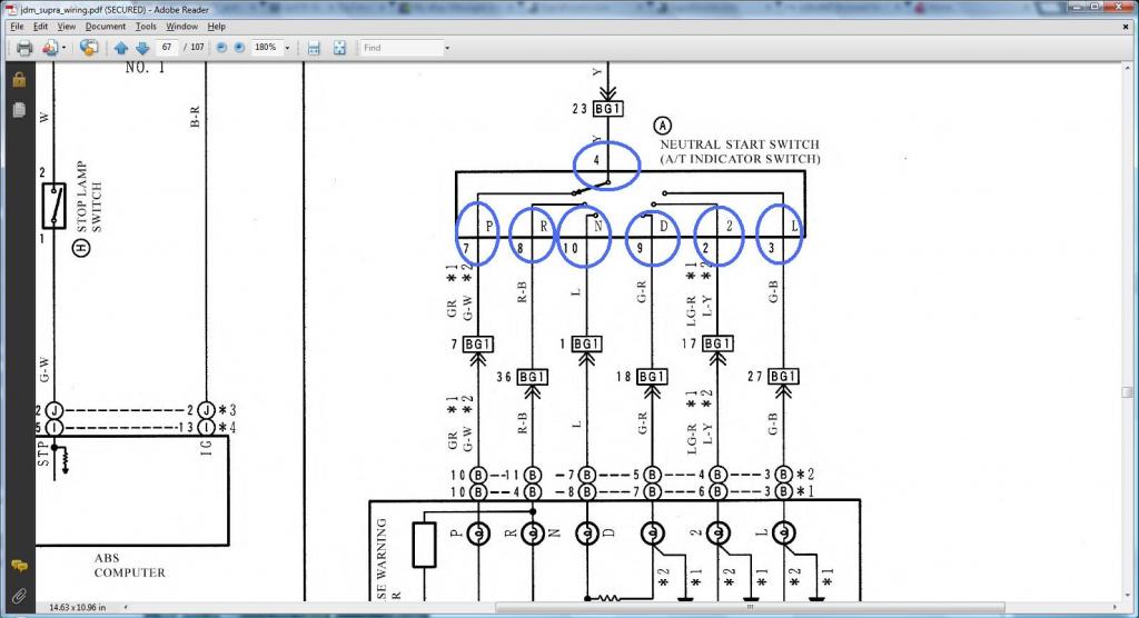
TAKE NOTE OF THE PIN NUMBERS
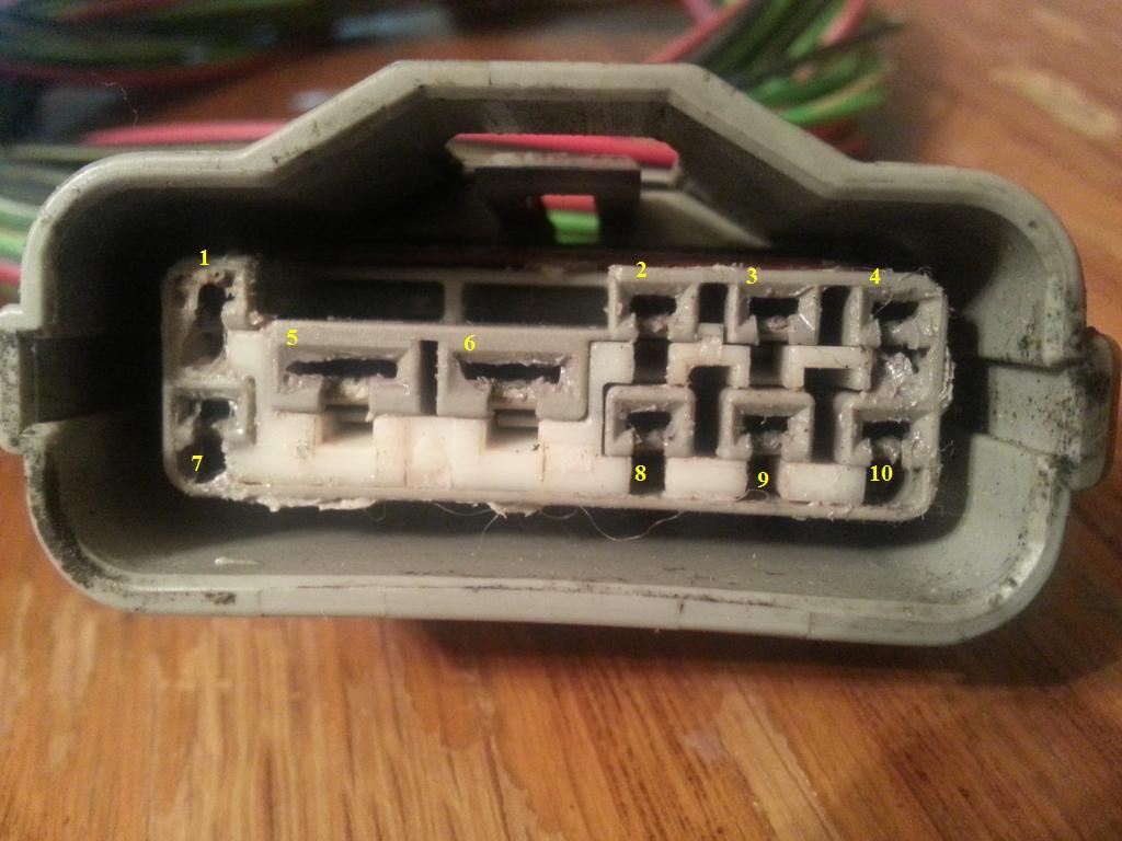
SC300 Read this diagram being on the right of the next diagram so you see continuous flow of current
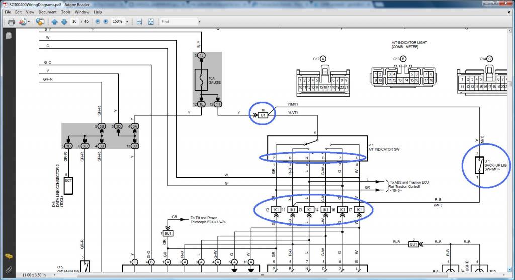
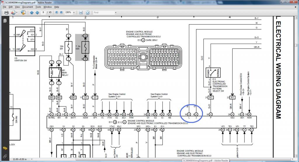
SC400 Read this diagram being on the right of the next diagram so you see continuous flow of current
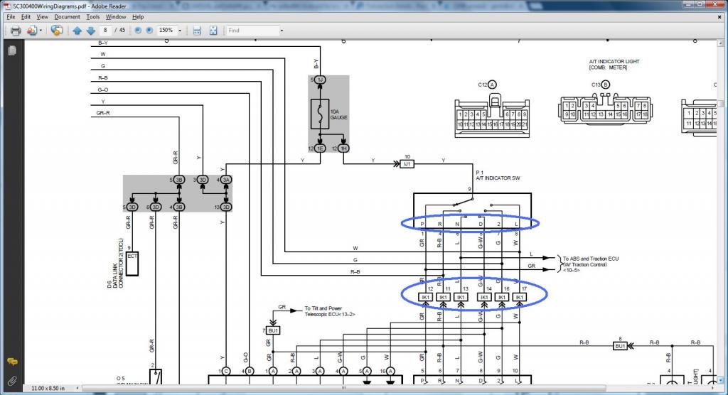
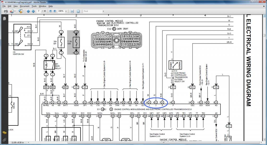
MKIV Read this diagram being on the right of the next diagram so you see continuous flow of current
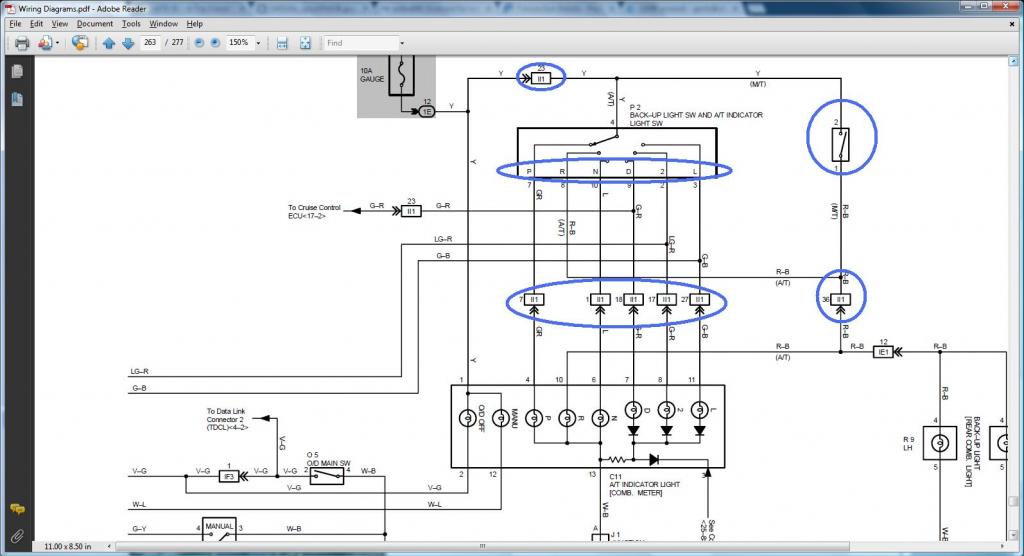
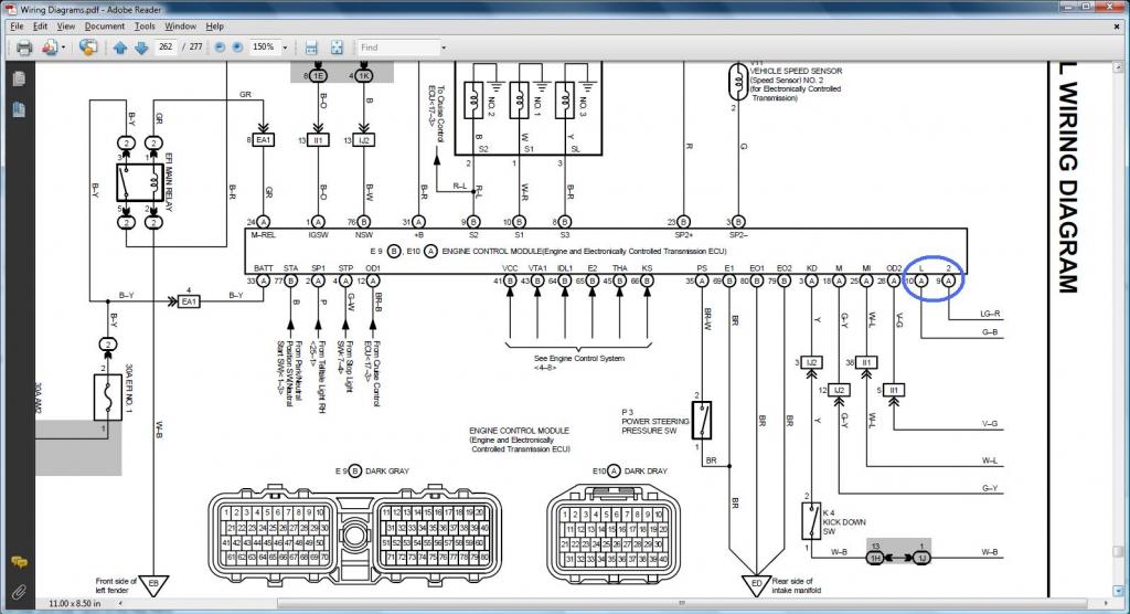
*** Transmission Solenoid (ECT Solenoid) ***
Pin 2 of Transmission Solenoid (should go to (Pin 12 of the Data Link Connector & to ( SC3 IJ1-12 & EB2-1 & Short-4 , SC4 IJ1-12 & EB2-3 , MK4 EA3-3 )))
Pin 3 of Transmission Solenoid (should go to (Pin 12 of the Data Link Connector & to ( SC3 IJ1-12 & EB2-1 & Short-4 , SC4 IJ1-12 & EB2-3 , MK4 EA3-3 )))
Read this diagram being on the right of the next diagram so you see continuous


*** A/T Indicator Switch ***
Pin 2 of A/T Indicator Switch (should go to Pin 9 of the 40 pin ECU Connector & to ( SC3 IK1-16 , SC4 IK1-16 , MK4 II1-17 ))
Pin 3 of A/T Indicator Switch (should go to Pin 10 of the 40 pin ECU Connector & to ( SC3 IK1-17 , SC4 IK1-17 , MK4 II1-27 ))
Pin 4 of A/T Indicator Switch (should go to ( SC3 IJ1-10 , SC4 IJ1-10 , MK4 II1-23 ))
Pin 5 of A/T Indicator Switch (should go to (SC3 IK2-23, SC4 IK2-23, MK4 IJ2-9))
Pin 6 of A/T Indicator Switch (should go to (SC3 IJ1-6, SC4 IJ1-6, MK4 IJ2-13))
Pin 7 of A/T Indicator Switch (should go to ( SC3 IK1-12 , SC4 IK1-12 , MK4 II1-7 ))
Pin 8 of A/T Indicator Switch (should go to Pin 7 of the 40 pin ECU Connector & to( SC3 IK1-11 , SC4 IK1-11 , MK4 II1-36 ))
Pin 9 of A/T Indicator Switch (should go to ( SC3 IK1-14 , SC4 IK1-14 , MK4 II1-18 ))
Pin 10 of A/T Indicator Switch (should go to ( SC3 IK1-13 , SC4 IK1-13 , MK4 II1-1 ))
I want you to pay attention on the next diagram for the 2jzgte Auto Transmission indicator switch numbering. I have encircled those numbers. This is what we are going to use. When I post the indicator switch of the SC300 / SC400 later , they have a different numbering but don't worry about it. It's this numbering on the next diagram that matters.
Pin 7 - Park
Pin 8 - Reverse
Pin 10- Neutral
Pin 9 - Drive
Pin 2 - 2nd Gear
Pin 3 - Low / 1st Gear

TAKE NOTE OF THE PIN NUMBERS

SC300 Read this diagram being on the right of the next diagram so you see continuous flow of current


SC400 Read this diagram being on the right of the next diagram so you see continuous flow of current


MKIV Read this diagram being on the right of the next diagram so you see continuous flow of current


Last edited by gerrb; 03-25-15 at 04:24 PM.
01-31-14, 04:55 PM
#55
Let us now deal with the connectors on this area .. quite a bit as you see.
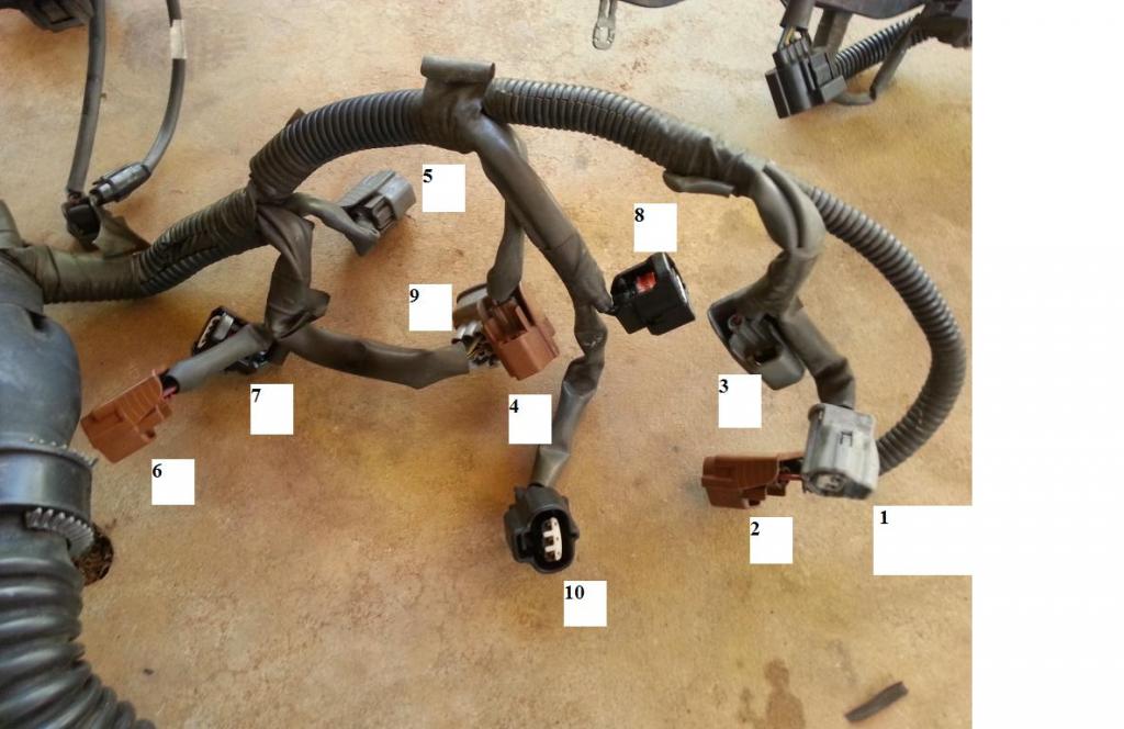
The INFO you will need to do THE DRILL
1) Intake Air Temp Sensor (IAT)
Pin 2 of IAT goes to pin 45 of 80 pin ECU Connector
Pin 1 of IAT goes to pin 65 of 80 pin ECU Connector
2) Injector #2
Piin 1 of Injector #2 goes to pin 19 of 80 pin ECU Connector
Pin 2 of Injector #2 (should go to (SC3 IJ1-7 or IJ1-3 & short 3 & short 5 , SC40 EB2-2 , MK4 IJ1-9))
3) Injector #3
Pin 1 of Injector #3 goes to pin 18 of 80 pin ECU Connector
Pin 2 of Injector #3 (should go to (SC3 IJ1-7 or IJ1-3 & short 3 & short 5 , SC40 EB2-2 , MK4 IJ1-9))
4) Injector #4
Pin 1 of Injector #4 goes to pin 17 of 80 pin ECU Connector
Pin 2 of Injector #4 (should go to (SC3 IJ1-7 or IJ1-3 & short 3 & short 5 , SC40 EB2-2 , MK4 IJ1-9))
5) Injector #5
Pin 1 of Injector #5 goes to pin 16 of 80 pin ECU Connector
Pin 2 of Injector #5 (should go to (SC3 IJ1-7 or IJ1-3 & short 3 & short 5 , SC40 EB2-2 , MK4 IJ1-9))
6) Injector #6
Pin 1 of Injector #6 goes to pin 15 of 80 pin ECU Connector
Pin 2 of Injector #6 (should go to (SC3 IJ1-7 or IJ1-3 & short 3 & short 5 , SC40 EB2-2 , MK4 IJ1-9))
7) Cam Sensor #2
Pin 1 of Cam Sensor #2 goes to pin 25 of 80 pin ECU Connector
Pin 2 of Cam Sensor #2 goes to pin 5 of 80 pin ECU Connector
8) Cam Sensor #1
Pin 1 of Cam Sensor #1 goes to pin 26 of 80 pin ECU Connector
Pin 2 of Cam Sensor #1 goes to pin 6 of 80 pin ECU Connector
9) IACV
Pin 1 of IACV goes to pin 34 of 80 pin ECU Connector
Pin 2 of IACV goes to pin 31 of 40 pin ECU Connector
Pin 3 of IACV goes to pin 32 of 80 pin ECU Connector
Pin 4 of IACV goes to pin 35 of 80 pin ECU Connector
Pin 5 of IACV goes to pin 31 of 40 pin ECU Connector
Pin 6 of IACV goes to pin 33 of 80 pin ECU Connector
10)Manifold Air Pressure Sensor (MAP / Turbo Pressure Sensor / Vacuum Sensor )
Pin 1 of Map Sensor goes to Pin 65 of 80 pin ECU Connector
Pin 2 of MAP Sensor goes to pin 62 of 80 pin ECU Connector
Pin 3 of MAP Sesor goes to pin 41 of 80 pin ECU Connector
NOTE : You be careful on the IACV . Take note of Pin 2 and 5 of the IACV . They go to the 40 pin ECU Connector . We will eventually have to start populating the 40 pin ECU connector.
Guys , time to do THE DRILL .
Last edited by gerrb; 02-01-14 at 05:30 AM.
01-31-14, 04:58 PM
#56
Aaron was gonna use some EV14 connectors for his aftermarket injectors so I have installed them on his harness.
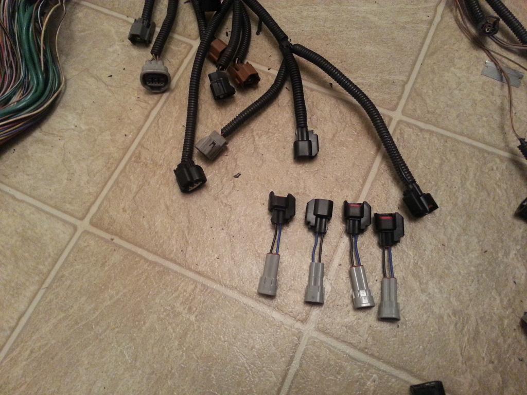
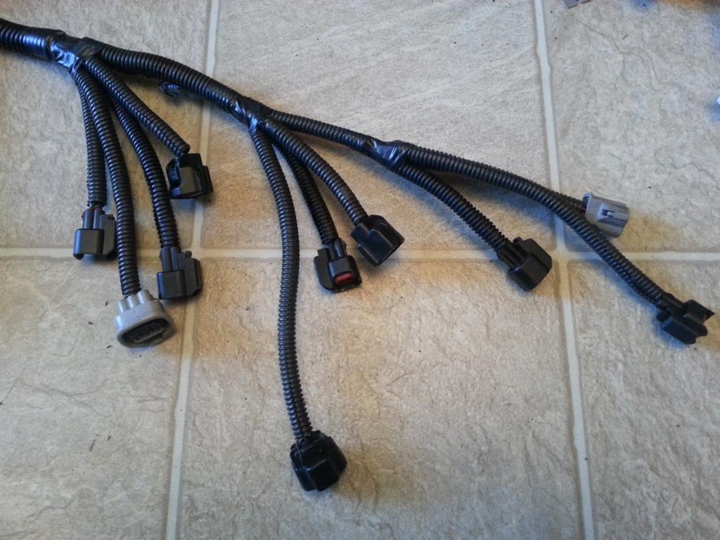
For now I kept the stock injector plugs on the Red Mamba 2 harness
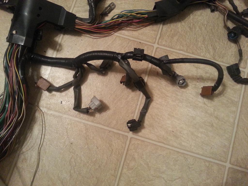
Once you are all done working on all the plugs on the Aristo 2jzgte harness , theoretically , all wires on the 80 pin ECU should have been extended or if not needed were removed and all the pins / wires on the Big Gray Aristo Plug are removed.
With Aaron's harness , it was not the case. Let me give you a picture of what is left on the 80 pin ECU Connector that have not been extended and what is left on the Big Gray Aristo plug.
Pin 4 , 9 , 29 & 77 on the 80 pin ECU Connector. They are the 4 wires going up in the picture.
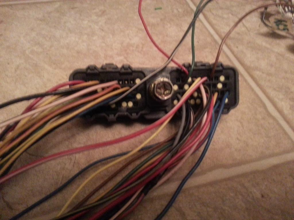
D2. E4. E5, F1, F14
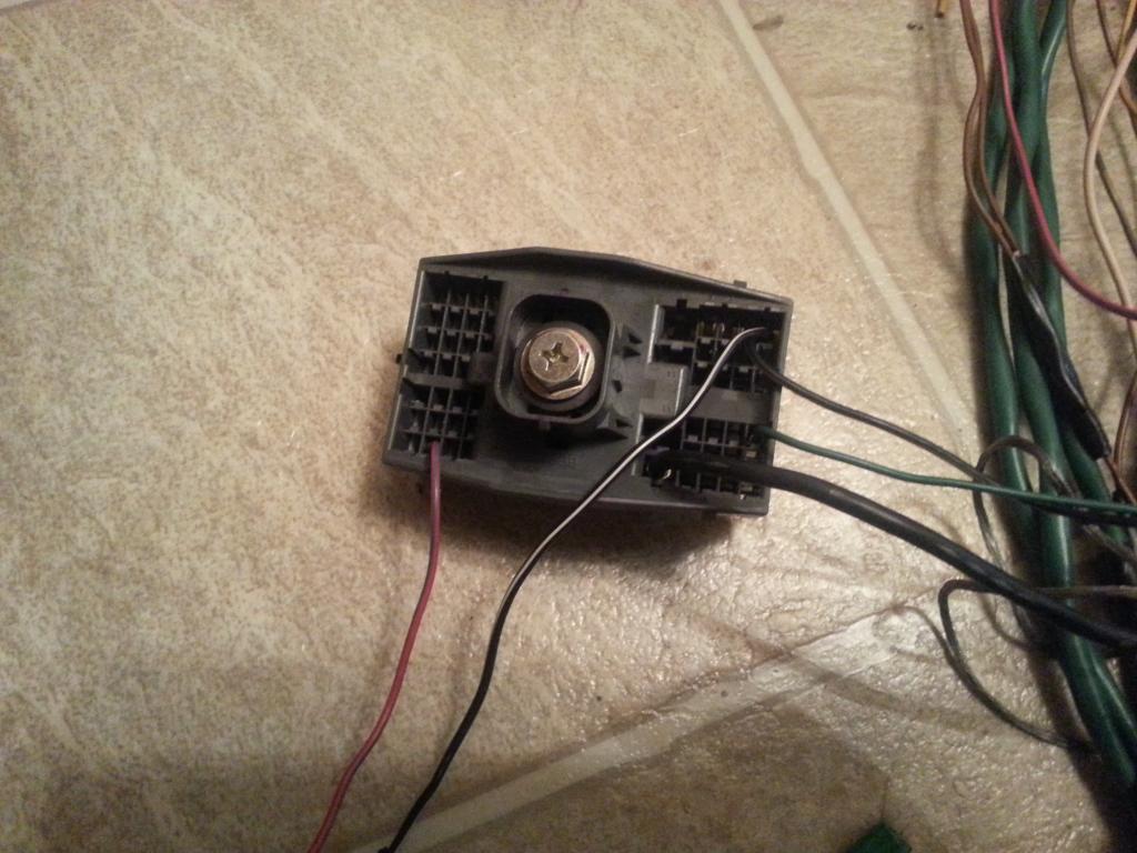
On this instance , you will have to evaluate what the wires are for... Check the 80 pin REFERENCE INFO .
Pin 4 is for Ground - Keep it , extend the wire
Pin 9 goes to Aristo D2 and is for AutoTrans - Remove it from 80 pin ECU connector and Aristo Plug since it is not needed.
Pin 29 is for VF1 and is connected to Diagnostic Port - Keep it , extend the wire
Pin 77 is for STA (starter signal) and goes to Aristo E4 , extend it ... (remove at Aristo and label the end)
F1 is for Starter , remove it from Aristo Plug and label it
E4 goes to Pin 77 (STA) remove it from Aristo Plug and label it
E5 is for starter relay trigger remove it from Aristo Plug and label it
D2 goes to Pin 9 and is for Auto Trans - Remove.. not needed.
F14 is for IDL1 , remove from Aristo and label it.
The REFERENCE INFO sheet will help you decide whether you need the left over wires or not.
Last edited by gerrb; 02-01-14 at 04:08 PM.
01-31-14, 04:59 PM
#57
Let us update our CHART
80 PIN ECU CONNECTOR
1 Pin 1 of O/D Direct Clutch Speed Sensor CHECKED
2 EMPTY
3 Pin 2 of A/T Rotation Sensor (Speed Sensor 2) CHECKED
4 Pin 69,79,80 of the 80 pin connector CHECKED
5 Pin 2 of the Camshaft Sensor # 2 CHECKED
6 Pin 2 of the Camshaft Sensor #1 CHECKED
7 Pin 2 of the Crankshaft Position Sensor CHECKED
8 EMPTY
9 Pin 8 of Transmission Solenoid CHECKED
10 Pin 4 of Transmission Solenoid CHECKED
11 EMPTY
12 Pin 5 of Transmission Solenoid CHECKED
13 Pin 6 of Transmission Solenoid CHECKED
14 Pin 7 of Transmission Solenoid CHECKED
15 Pin 1 of the Injector No. 6 CHECKED
16 Pin 1 of the Injector No. 5 CHECKED
17 Pin 1 of the Injector No. 4 CHECKED
18 Pin 1 of the Injector No. 3 CHECKED
19 Pin 1 of the Injector No. 2 CHECKED
20 Pin 1 of the Injector No. 1 CHECKED
21 Pin 2 of O/D Direct Clutch Speed Sensor CHECKED
22 EMPTY
23 Pin 1 of A/T Rotation Speed Sensor (Speed Sensor 2) CHECKED
24 Pin 2 of the A/T Fluid Temp Sensor CHECKED
25 Pin 1 of the Camshaft Sensor #2 CHECKED
26 Pin 1 of the Camshaft Sensor #1 CHECKED
27 Pin 1 of the Crankshaft Position Sensor CHECKED
28 EMPTY
29 Pin 13 (VF1) of Diagnostic Port Pin 29 of the 80 pin ECU Connector ( SC3 IK1-3 , SC4 IK1-3 , MK4 IJ1-13 )) CHECKED
30 EMPTY
31 Pin 1 of Transmission Solenoid CHECKED
32 Pin 3 of IACV CHECKED
33 Pin 6 of IACV CHECKED
34 Pin 1 of IACV CHECKED
35 Pin 4 of IACV CHECKED
36 EMPTY
37 EMPTY
38 Pin 2 of the VSV3 CHECKED
39 Pin 2 of the VSV2 CHECKED
40 Pin 2 of the VSV1 CHECKED
41 Pin 1 of the TPS Pin 4 of the Sub-TPS Pin 3 of MAP CHECKED
42 Pin 3 of the Sub-TPS CHECKED (used this as extra wire on my setup)
43 Pin 2 of the TPS CHECKED
44 Pin 2 of the Water Temperature Sensor CHECKED
45 Pin 2 of the Intake Air Temp Sensor CHECKED
46 EMPTY
47 EMPTY
48 Pin 3 of the O2 Sensor CHECKED
49 Pin 1 of the Knock Sensor 2 CHECKED
50 Pin 1 of the Knock Sensor 1 CHECKED
51 EMPTY
52 Pin 7 of the 12 pin Igniter Connector CHECKED
53 Pin 8 of the 12 pin igniter Connector CHECKED
54 Pin 9 of the 12 pin igniter Connector CHECKED
55 Pin 3 of the 12 pin igniter Connector CHECKED
56 Pin 2 of the 12 pin Igniter Connector CHECKED
57 Pin 1 of the 12 pin Igniter Connector CHECKED
58 Pin 3 of the 4 pin Igniter Connector CHECKED
59 EMPTY
60 Pin 2 of the VSVPMC CHECKED
61 EMPTY
62 Pin 2 of MAP CHECKED
63 Pin 2 of the Sub-TPS CHECKED (used this as extra wire on my setup)
64 Pin 3 of the TPS CHECKED
65 Pin 1 of the Water Temperature Sensor Pin 4 of the TPS Pin 1 of the Sub-TPS Pin 1 of A/T Fluid Temp Sensor Pin 1 of IAT Pin 1 of MAP CHECKED
66 EMPTY
67 EMPTY
68 EMPTY
69 Rear Intake Manifold Ground CHECKED
70 EMPTY
71 Pin 1 of the O2 Sensor CHECKED
72 EMPTY
73 EMPTY
74 Pin 2 of the VSVEVAP CHECKED
75 EMPTY
76 Pin 6 of IJ1
77 Pin 1 of EB2
78 EMPTY
79 Rear Intake Manifold Ground CHECKED
80 Rear Intake Manifold Ground CHECKED
4 PIN IGNITER CONNECTOR
1 Pin 12 of Plug F of Aristo plug ( Pin 19 of the Data Link Connector ( SC3 IK1-8 , SC4 IK1-8 , MK4 ))
2 Pin 6 of Plug F of Aristo plug Pin 1 of the Noise Filter ( SC3 IJ1-7 , SC4 EB2-2 , MK4 IJ1-1 or IJ1-9 )
3 Pin 58 of the 80 pin ECU connector CHECKED
4 Ground Connector on the Front Side of Intake Manifold Pin 2 of the Noise filter Connector CHECKED
12 PIN IGNITER CONNECTOR
1 Pin 57 of the 80 pin ECU connector CHECKED
2 Pin 56 of the 80 pin ECU connector CHECKED
3 Pin 55 of the 80 pin ECU connector CHECKED
4 Pin 2 of the Ignition Coil Connector 3 CHECKED
5 Pin 2 of the Ignition Coil Connector 2 CHECKED
6 Pin 2 of the Ignition Coil Connector 1 CHECKED
7 Pin 52 of the 80 pin ECU connector CHECKED
8 Pin 53 of the 80 pin ECU connector CHECKED
9 Pin 54 of the 80 pin ECU connector CHECKED
10 Pin 2 of the Ignition Coil Connector 4 CHECKED
11 Pin 2 of the Ignition Coil Connector 5 CHECKED
12 Pin 2 of the Ignition Coil Connector 6 CHECKED
AC COMPRESSOR PLUG
1 Pin 1 of Plug C of the Aristo Plug (should go to (SC3 EB1-7 & II1-1 , SC4 EB1-7 & II1-1 , MK4 II1-26 ))
2 Pin 2 of Plug C of the Aristo Plug (should go to (SC3 II1-4 , SC4 II1-4 , MK4 II1-20 ))
4 Pin 5 of Plug C of the Aristo Plug (should go to (SC3 EB1-1 , SC4 EB1-1 , MK4 EA1-1 & II1-10 ))
A/T FLUID TEMP SENSOR
1 Pin 65 of 80 pin ECU Connector CHECKED
2 Pin 24 of 80 pin ECU Connector CHECKED
A/T ROTATION SPEED SENSOR (Speed Sensor 2)
1 Pin 23 of 80 pin ECU Connector CHECKED
2 Pin 3 of 80 pin ECU Connector CHECKED
A/T INDICATOR SWITCH
2 Pin 9 of Plug E of the Big Aristo Plug (should go to Pin 9 of the 40 pin ECU Connector & to ( SC3 IK1-16 , SC4 IK1-16 , MK4 II1-17 ))
3 Pin 10 of Plug E of the Big Aristo Plug (should go to Pin 10 of the 40 pin ECU Connector & to ( SC3 IK1-17 , SC4 IK1-17 , MK4 II1-27 ))
4 Pin 14 of Plug E of the Big Aristo Plug (should go to ( SC3 IJ1-10 , SC4 IJ1-10 , MK4 II1-23 ))
5 Pin 12 of Plug E of the Big Aristo Plug (should go to (SC3 IK2-23, SC4 IK2-23, MK4 IJ2-9))
6 Pin 5 of Plug E of the Big Aristo Plug (should go to (SC3 IJ1-6, SC4 IJ1-6, MK4 IJ2-13))
7 Pin 4 of Plug E of the Big Aristo Plug (should go to ( SC3 IK1-12 , SC4 IK1-12 , MK4 II1-7 ))
8 Pin 13 of Plug E of the Big Aristo Plug (should go to Pin 7 of the 40 pin ECU Connector & to ( SC3 IK1-11 , SC4 IK1-11 , MK4 II1-36 ))
9 Pin 11 of Plug E of the Big Aristo Plug (should go to ( SC3 IK1-14 , SC4 IK1-14 , MK4 II1-18 ))
10 Pin 8 of Plug E of the Big Aristo Plug (should go to ( SC3 IK1-13 , SC4 IK1-13 , MK4 II1-1 ))
CAM SENSOR #2
1 Pin 25 of 80 pin ECU Connector CHECKED
2 Pin 5 of 80 pin ECU Connector CHECKED
CAM SENSOR #1
1 Pin 26 of 80 pin ECU Connector CHECKED
2 Pin 6 of 80 pin ECU Connector CHECKED
CRANKSHAFT POSITION SENSOR
1 Pin 27 of the 80 pin ECU Connector CHECKED
2 Pin 7 of the 80 pin ECU Connector CHECKED
DIAGNOSTIC PORT
1 (FP) Pin 15 of Plug C of the Big Gray Aristo Plug (should go to (SC3 IJ1-1 , SC4 IJ1-1 , MK4 IJ1-8 ))
2 (W) Pin 2 of Plug E of the Big Gray Aristo Plug (should go to Pin 6 of the 40 pin ECU Connector & to (SC3 IK2-9 , SC4 IK2-9 , MK4 II1-15 ))
3 (E1) Pin 11 of Plug F of the Big Gray Aristo Plug (should go to Rear Intake Manifold Ground & to (SC3 Pin 69,79,80 of the 80 pin ECU Connector , SC4 IK1-1 & Pin 69,79,80 of the 80 pin ECU Connector , MK4 IJ1-18 ))
4 (OX1) Pin 48 of the 80 pin ECU Connector
5 (AB) Pin 4 of Plug D of the Big Gray Aristo Plug
6 (OP1) Pin 10 of Plug D of the Big Gray Aristo Plug
7 (CCo) Pin 8 of Plug D of the Big Gray Aristo Plug
8 (TE1) Pin 4 of Plug F of the Big Gray Aristo Plug(should go to Pin 20 of the 40 pin ECU Connector & to ( SC3 IK1-4 , SC4 IK1-4 , MK4 IJ1-5 ))
9 (TE2) Pin 7 of Plug E of the Big Gray Aristo Plug (should go to Pin 19 of the 40 pin ECU Connector & to ( SC3 IK1-2 , SC4 IK1-2 , MK4 IJ1-17 ))
11 (TC) Pin 6 of Plug E of the Big Gray Aristo Plug
12 (+B) Pin 3 of Plug E of the Big Gray Aristo Plug (should go to (SC3 IJ1-12 & EB2-1 & Short-4 & Pin 2 of O2 Sensor , SC4 IJ1-12 & EB2-3 & Pin 2 of O2 Sensor , MK4 EA3-3 & Pin 31 of 40 pin ECU Connector ))
13 (VF1)Pin 10 of Plug F of the Big Gray Aristo Plug (should go to Pin 29 of the 80 pin ECU Connector & to ( SC3 IK1-3 , SC4 IK1-3 , MK4 IJ1-13 ))
16 (TS) Pin 5 of Plug F of the Big Gray Aristo Plug
18 (TEM) Pin 5 of Plug D of the Big Gray Aristo Plug
19 (IG-) Pin 1 of the 4 pin Igniter Connector
22 (WA) PIn 7 of Plug D of the Big Gray Aristo Plug
23 (WB) Pin 11 of Plug D of the Big Gray Aristo Plug
GROUND - Front Intake Manifold
1 Pin 2 of Noise Filter CHECKED
GROUND - Rear Intake Manifold
1 Pin 69 Pin 79 Pin 80 of the 80 pin ECU Connector CHECKED
IACV
1 Pin 34 of 80 pin ECU Connector CHECKED
2 Pin 31 of 40 pin ECU Connector
3 Pin 32 of 80 pin ECU Connector CHECKED
4 Pin 35 of 80 pin ECU Connector CHECKED
5 Pin 31 of 40 pin ECU Connector
6 Pin 33 of 80 pin ECU Connector CHECKED
IGNITION COIL 1
1 Pin 1 of the Noise Filter Pin 2 of the 4 pin Igniter Connector Pin 1 of Ignition Coil 2,3,4,5,6 ( SC3 IJ1-7 , SC4 EB2-2 , MK4 IJ1-1 or IJ1-9 )
2 Pin 6 of the 12 Pin Igniter Connector CHECKED
IGNITION COIL 2
1 Pin 1 of the Noise Filter Pin 2 of the 4 pin Igniter Connector Pin 1 of Ignition Coil 1,3,4,5,6 ( SC3 IJ1-7 , SC4 EB2-2 , MK4 IJ1-1 or IJ1-9 )
2 Pin 5 of the 12 Pin Igniter Connector CHECKED
IGNITION COIL 3
1 Pin 1 of the Noise Filter Pin 2 of the 4 pin Igniter Connector Pin 1 of Ignition Coil 1,2,4,5,6 ( SC3 IJ1-7 , SC4 EB2-2 , MK4 IJ1-1 or IJ1-9 )
2 Pin 4 of the 12 Pin Igniter Connector CHECKED
IGNITION COIL 4
1 Pin 1 of the Noise Filter Pin 2 of the 4 pin Igniter Connector Pin 1 of Ignition Coil 1,2,3,5,6 ( SC3 IJ1-7 , SC4 EB2-2 , MK4 IJ1-1 or IJ1-9 )
2 Pin 10 of the 12 Pin Igniter Connector CHECKED
IGNITION COIL 5
1 Pin 1 of the Noise Filter Pin 2 of the 4 pin Igniter Connector Pin 1 of Ignition Coil 1,2,3,4,6 ( SC3 IJ1-7 , SC4 EB2-2 , MK4 IJ1-1 or IJ1-9 )
2 Pin 11 of the 12 Pin Igniter Connector CHECKED
IGNITION COIL 6
1 Pin 1 of the Noise Filter Pin 2 of the 4 pin Igniter Connector Pin 1 of Ignition Coil 1,2,3,4,5 ( SC3 IJ1-7 , SC4 EB2-2 , MK4 IJ1-1 or IJ1-9 )
2 Pin 12 of the 12 Pin Igniter Connector CHECKED
INJECTOR NO. 1
1 Pin 20 of the 80 pin ECU Connector CHECKED
2 (should go to (SC3 IJ1-7 or IJ1-3 & short 3 & short 5 , SC40 EB2-2 , MK4 IJ1-9))
INJECTOR NO. 2
1 Pin 19 of 80 pin ECU Connector CHECKED
2 (should go to (SC3 IJ1-7 or IJ1-3 & short 3 & short 5 , SC40 EB2-2 , MK4 IJ1-9))
INJECTOR NO. 3
1 Pin 18 of 80 pin ECU Connector CHECKED
2 (should go to (SC3 IJ1-7 or IJ1-3 & short 3 & short 5 , SC40 EB2-2 , MK4 IJ1-9))
INJECTOR NO. 4
1 Pin 17 of 80 pin ECU Connector CHECKED
2 (should go to (SC3 IJ1-7 or IJ1-3 & short 3 & short 5 , SC40 EB2-2 , MK4 IJ1-9))
INJECTOR NO. 5
1 Pin 16 of 80 pin ECU Connector CHECKED
2 (should go to (SC3 IJ1-7 or IJ1-3 & short 3 & short 5 , SC40 EB2-2 , MK4 IJ1-9))
INJECTOR NO. 6
1 Pin 15 of 80 pin ECU Connector CHECKED
2 (should go to (SC3 IJ1-7 or IJ1-3 & short 3 & short 5 , SC40 EB2-2 , MK4 IJ1-9))
INTAKE AIR TEMP SENSOR (IAT)
1 Pin 65 of 80 pin ECU Connector CHECKED
2 Pin 45 of 80 pin ECU Connector CHECKED
KNOCK SENSOR 1
1 Pin 50 of the 80 pin ECU Connector CHECKED
KNOCK SENSOR 2
1 Pin 49 of the 80 pin ECU Connector CHECKED
MANIFOLD AIR PRESSURE SENSOR (MAP / Turbo Pressure / Vacuum Sensor )
1 Pin 65 of 80 pin ECU Connector CHECKED
2 Pin 62 of 80 pin ECU Connector CHECKED
3 Pin 41 of 80 pin ECU Connector CHECKED
NOISE FILTER
1 Pin 2 of the 4 pin Igniter Connector ( SC3 IJ1-7, SC4 EB2-2 , MK4 IJ1-1 or IJ1-9 )
2 Ground Connector on the Front Side of Intake Manifold Pin 4 of the 4 pin Igniter Connector CHECKED
O/D DIRECT CLUTCH SPEED SENSOR (O/D)
1 Pin 1 of 80 pin ECU Connector CHECKED
2 Pin 21 of 80 pin ECU Connector CHECKED
OIL LEVEL SENSOR PLUG
1 Pin 1 of Plug D of Big Gray Aristo Plug (should go to (SC3 IK2-10 , SC4 IK2-10 , MK4 II1-33 ))
2 Pin 7 of Plug F of Big Gray Aristo Plug(should go to ( SC3 / SC4 / MK4 Rear Intake Manifold Ground for all ))
OIL PRESSURE PLUG
1 Pin 8 of Plug F of the Aristo Plug (should go to ( SC3 IK1-20 , SC4 IK1-20 , MK4 II1-25 ))
STARTER
1 Pin 1 of Plug F of Big Gray Aristo Plug (should go to (SC3 EB2-1 , SC4 EB2-1 , MK4 EA3-1 ))
THROTTLE POSITION SENSOR
1 Pin 41 of the 80 pin ECU Connector CHECKED
2 Pin 43 of the 80 pin ECU Connector CHECKED
3 Pin 64 of the 80 pin ECU Connector CHECKED
4 Pin 65 of the 80 pin ECU Connector CHECKED
TRANSMISSION SOLENOID (ECT Solenoid)
1 Pin 31 of 80 pin ECU Connector CHECKED
2 Pin 3 of Plug E of the Big Aristo Plug (should go to (Pin 12 of the Data Link Connector & to ( SC3 IJ1-12 & EB2-1 & Short-4 , SC4 IJ1-12 & EB2-3 , MK4 EA3-3 )))
3 Pin 3 of Plug E of the Big Aristo Plug (should go to (Pin 12 of the Data Link Connector & to ( SC3 IJ1-12 & EB2-1 & Short-4 , SC4 IJ1-12 & EB2-3 , MK4 EA3-3 )))
4 Pin 10 of 80 pin ECU Connector CHECKED
5 Pin 12 of 80 pin ECU Connector CHECKED
6 Pin 13 of 80 pin ECU Connector CHECKED
7 Pin 14 of 80 pin ECU Connector CHECKED
8 Pin 9 of 80 pin ECU Connector CHECKED
WATER TEMPERATURE SENSOR
1 Pin 65 of the 80 pin ECU Connector CHECKED
2 Pin 44 of the 80 pin ECU Connector CHECKED
WATER TEMPERATURE GAUGE SENDER
1 Pin 9 of Plug F of the Big Gray Aristo Plug (should go to SC3 IK1-9 , SC4 IK1-9 & Short-3 , MK4 II1-19 )
The following plugs are necessary only if you are going stock 2jzgte setup
OXYGEN SENSOR (O2)
1 Pin 71 of the 80 pin ECU Connector CHECKED
2 Pin 3 of Plug E of Aristo Plug (Pin 12 of the Data Link Connector ( SC3 IJ1-12 & EB2-1 & Short-4 , SC4 IJ1-12 & EB2-3 , MK4 EA3-3 ))
3 Pin 48 of the 80 pin ECU Connector CHECKED
VSV1 ( Air Intake Control Valve )
1 Pin 2 of the O2 Sensor Pin 1 of the VSV3 (Pin 12 of the Data Link Connector ( SC3 IJ1-12 & EB2-1 & Short-4 , SC4 IJ1-12 & EB2-3 , MK4 EA3-3 ))
2 Pin 40 of the 80 pin ECU Connector CHECKED
VSV2 ( Exhaust Control Valve )
1 Pin 1 of VSV1 , VSV3 , VSVPMC Pin 2 of the O2 Sensor Pin 1 of the VSV3 (Pin 12 of the Data Link Connector ( SC3 IJ1-12 & EB2-1 & Short-4 , SC4 IJ1-12 & EB2-3 , MK4 EA3-3 ))
2 Pin 39 of the 80 pin ECU Connector CHECKED
VSV3( Exhaust Bypass Valve )
1 Pin 2 of the O2 Sensor Pin 1 of the VSV1 (Pin 12 of the Data Link Connector ( SC3 IJ1-12 & EB2-1 & Short-4 , SC4 IJ1-12 & EB2-3 , MK4 EA3-3 ))
2 Pin 38 of the 80 pin ECU Connector CHECKED
VSVEVAP ( Canister Purge )
1 Pin 1 of VSV1 , VSV2 , VSV3 , VSVPMC (Pin 12 of the Data Link Connector ( SC3 IJ1-12 & EB2-1 & Short-4 , SC4 IJ1-12 & EB2-3 , MK4 EA3-3 ))
2 Pin 74 of the 80 pin ECU Connector CHECKED
VSVPMC ( Waste Gate Valve )
1 Pin 1 of VSV1 , VSV2 , VSV3 Pin 2 of the O2 Sensor Pin 1 of the VSV3 (Pin 12 of the Data Link Connector ( SC3 IJ1-12 & EB2-1 & Short-4 , SC4 IJ1-12 & EB2-3 , MK4 EA3-3 ))
2 Pin 60 of the 80 pin ECU Connector CHECKED
The following plugs maybe kept or deleted depending on your seup
Sub-Throttle Position Sensor
1 Pin 65 of the 80 pin ECU Connector CHECKED
2 Pin 63 of the 80 pin ECU Connector CHECKED
3 Pin 42 of the 80 pin ECU Connector CHECKED
4 Pin 41 of the 80 pin ECU Connector CHECKED
The following plugs are usually deleted
Throttle Motor Valve
1 Pin 8 of Plug C of Big Gray Aristo Plug
2 Pin 11 of Plug C of Big Gray Aristo Plug
3 Pin 7 of Plug C of Big Gray Aristo Plug
4 Pin 4 of Plug C of Big Gray Aristo Plug
5 Pin 6 of Plug C of Big Gray Aristo Plug
6 Pin 3 of Plug C of Big Gray Aristo Plug
The following plug definitely will be deleted but its wires go to different body plugs or 40 pin ECU Connector or can be used for future needs
BIG GRAY ARISTO PLUG
PLUG C
1 (SC3 EB1-7 & II1-1 , SC4 EB1-7 & II1-1 , MK4 II1-26 ))
2 (should go to (SC3 II1-4 , SC4 II1-4 , MK4 II1-20 ))
3 Extra Wire for future use CHECKED
4 Extra Wire for future use CHECKED
5 (should go to (SC3 EB1-1 , SC4 EB1-1 , MK4 EA1-1 & II1-10 ))
6 Extra Wire for future use CHECKED
7 Extra Wire for future use CHECKED
8 Extra Wire for future use CHECKED
11 Extra Wire for future use CHECKED
13 Extra Wire for future use CHECKED
15 Pin 1 (FP) of Diagnostic Port goes (should go to (SC3 IJ1-1 , SC4 IJ1-1 , MK4 IJ1-8 ))
PLUG D
1 (should go to (SC3 IK2-10 , SC4 IK2-10 , MK4 II1-33 ))
4 Pin 5 (AB) of Diagnostic Port
5 Pin 18 (TEM) of Diagnostic Port
6 Pin 63 of the 80 pin ECU Connector (Is still needed ????? remains to be seen during the merge process)
7 Pin 22 (WA) of Diagnostic Port
8 Pin 7 (CCo) of Diagnotic Port
9 Extra Wire for future use CHECKED
10Pin 6 (OP1) of Diagnostic Port
11Pin 23 (WB) of Diagnostic Port
PLUG E
2 Pin 2 (W) of Diagnostic Port (should go to Pin 6 of the 40 pin ECU Connector & to (SC3 IK2-9 , SC4 IK2-9 , MK4 II1-15 ))
3 Pin 2 of Oxygen Sensor Pin 2 & Pin 3 of Transmission Solenoid Pin 31 of 40 pin ECU Connector (Pin 12 of the Data Link Connector ( SC3 IJ1-12 & EB2-1 & Short-4 , SC4 IJ1-12 & EB2-3 , MK4 EA3-3 ))
4 Pin 12 (+B) of Diagnostic Port Pin 7 of A/T Indicator Switch (should go to (SC3 IJ1-12 & EB2-1 & Short-4 & Pin 2 of O2 Sensor & IK1-12 , SC4 IJ1-12 & EB2-3 & Pin 2 of O2 Sensor & IK1-12 , MK4 EA3-3 & Pin 31 of 40 pin ECU Connector & II1-7 ))
5 Pin 6 of A/T Indicator Switch
6 Pin 11 (TC) of Diagnostic Port
7 Pin 9 (TE2) of Diagnostic Port (should go to Pin 19 of the 40 pin ECU Connector & to ( SC3 IK1-2 , SC4 IK1-2 , MK4 IJ1-17 ))
8 Pin 10 of A/T Indicator Switch (should go to ( SC3 IK1-13 , SC4 IK1-13 , MK4 II1-1 ))
9 Pin 2 of A/T Indicator Switch (should go to Pin 9 of the 40 pin ECU Connector & to ( SC3 IK1-16 , SC4 IK1-16 , MK4 II1-17 ))
10 Pin 3 of A/T Indicator Switch (should go to Pin 10 of the 40 pin ECU Connector & to ( SC3 IK1-17 , SC4 IK1-17 , MK4 II1-27 ))
11 Pin 9 of A/T Indicator Switch (should go to ( SC3 IK1-14 , SC4 IK1-14 , MK4 II1-18 ))
12 Pin 5 of A/T Indicator Switch
13 Pin 8 of A/T Indicator Switch (should go to Pin 7 of the 40 pin ECU Connector & to ( SC3 IK1-11 , SC4 IK1-11 , MK4 II1-36 ))
14 Pin 4 of A/T Indicator Switch (should go to ( SC3 IJ1-10 , SC4 IJ1-10 , MK4 II1-23 ))
PLUG F
4 Pin 8 (TE1) of Diagnostic Port ((should go to Pin 20 of the 40 pin ECU Connector & to ( SC3 IK1-4 , SC4 IK1-4 , MK4 IJ1-5 ))
5 Pin 16 (TS) of Diagnostic Port
6 Pin 1 of the Noise Filter ( SC3 IJ1-7 , SC4 EB2-2 , MK4 IJ1-1 or IJ1-9 )
7 (should go to ( SC3 / SC4 / MK4 Rear Intake Manifold Ground for all ))
8 (should go to ( SC3 IK1-20 , SC4 IK1-20 , MK4 II1-25 ))
9 Pin 1 of the Water Temperature Gauge Sender ( SC3 IK1-9 , SC4 IK1-9 & Short-3 , MK4 II1-19 )
10 Pin 13 (VF1) of Diagnostic Port (should go to Pin 29 of the 80 pin ECU Connector & to ( SC3 IK1-3 , SC4 IK1-3 , MK4 IJ1-13 ))
11 Pin 3 (E1) of Diagnostic Port (should go to Rear Intake Manifold Ground & to (SC3 Pin 69,79,80 of the 80 pin ECU Connector , SC4 IK1-1 & Pin 69,79,80 of the 80 pin ECU Connector , MK4 IJ1-18 ))
12 ( Pin 19 of the Data Link Connector & to ( SC3 IK1-8 , SC4 IK1-8 , MK4 ))
Last edited by gerrb; 02-11-19 at 12:54 PM.
01-31-14, 05:02 PM
#58
DIAGRAMS TO VERIFY PIN NUMBERING & WHERE THE WIRE GOES
*** Intake Air Temp Sensor (IAT) & Manifold Air Pressure Sensor (MAP / Turbo Pressure Sensor / Vacuum Sensor ) ***
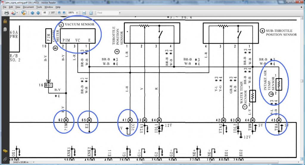
*** Cam Sensor #1 & Cam Sensor2 ***
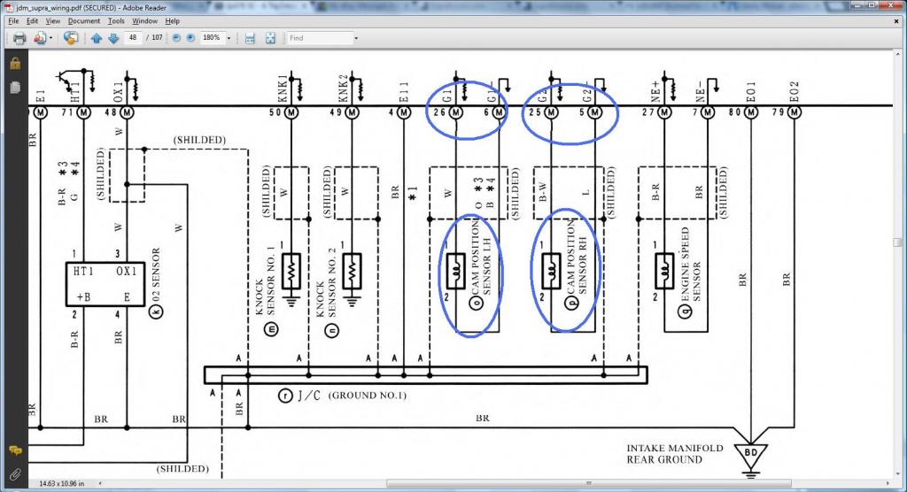
*** Injectors 2,3,4,5,6 ***
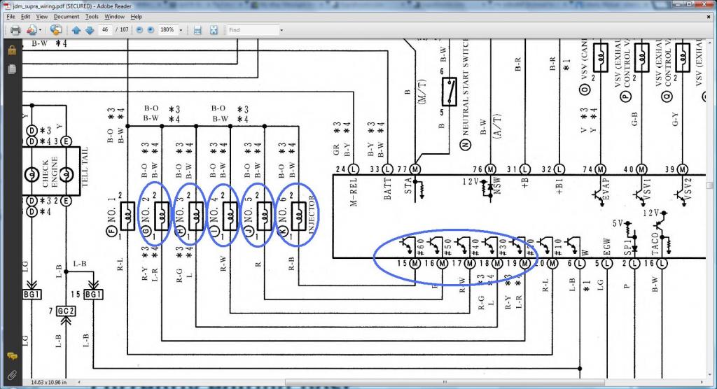
*** Idle Air Control Valve (IACV) ***
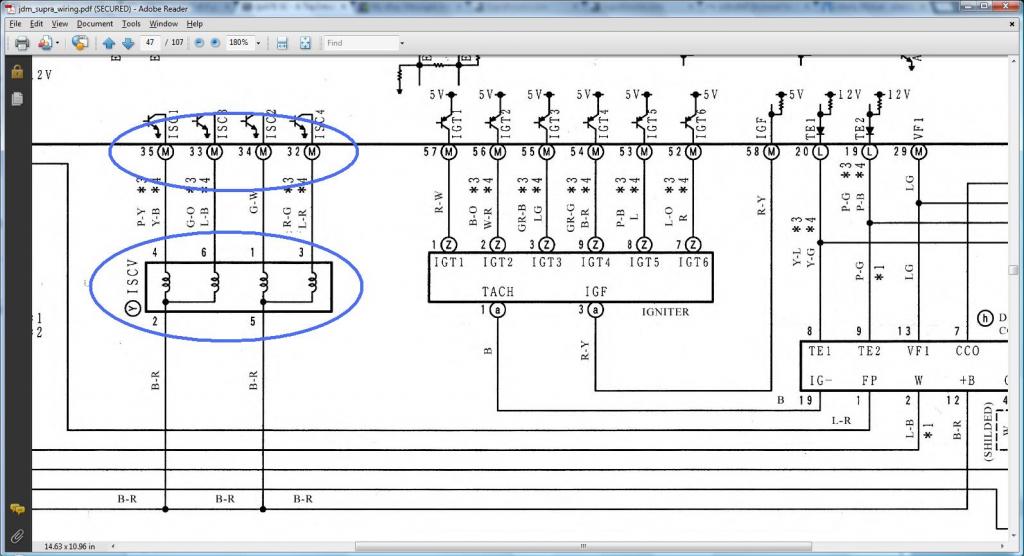
Read this diagram being on the right of the next diagram so you see continuous flow of current
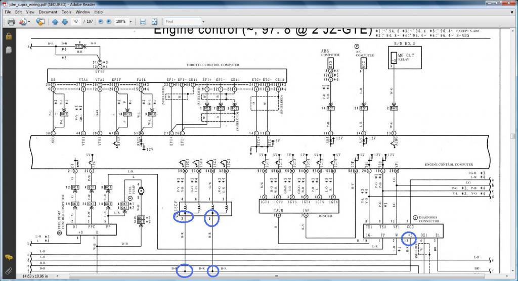
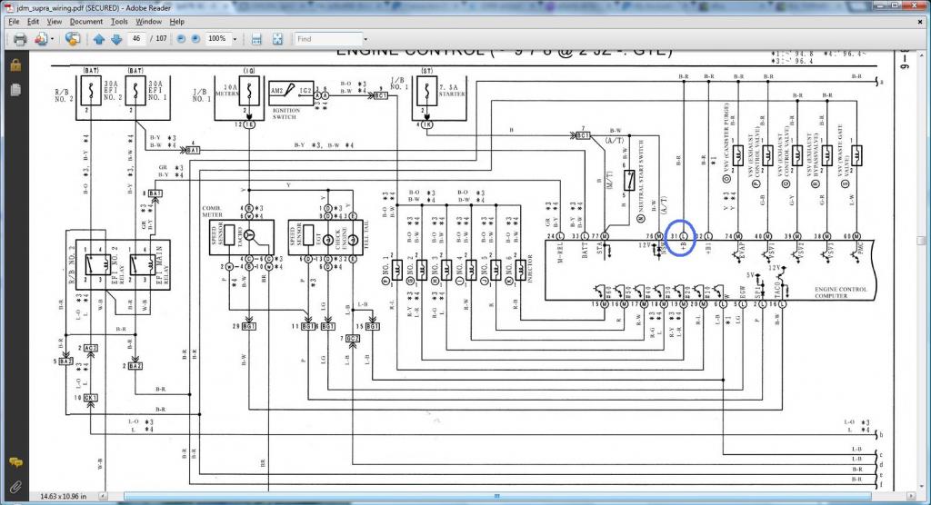


Last edited by gerrb; 02-01-14 at 05:33 AM.
01-31-14, 05:05 PM
#59
At this point , you should be done cleaning up your Aristo 2jzgte harness. Everything we have done so far was straight forward. We have been inspecting & replacing plugs that are broken , extending wires ( For me, this was actually the worst or most laborious part of making a 2jzgte harness.) , removing plugs / pins and wires that are not needed or in some instances keeping un-needed wires for some other purposes in the future , checking connectivity from one pin of a plug to another pin of another plug and lastly updating our chart. These, we are all doing so far on the plugs / pins / wires that are already on the Aristo 2jzgte harness. They are all properly laid out already so you don't have to do any measuring how long the wires will be or finding out where the plugs should be. That is the actual 2jzgte harness you are already working on. That is the very reason why I use it to start with as my base harness. Most of the plugs to get that engine running are already there.
On the first part of this 2jzgte Wiring Harness build thread , I have also enumerated the pin and plug where a particular wire should go not only for the SC300 but also for the SC400 and the MKIV NA . Once you have your 40 pin ECU and body plugs , you should know what wires are going into them. Though there are other 40 pin ECU and body plugs pins / wires that have not yet been covered, we will eventually get into them on PART IV OTHERS.
NOTE : This is a classic example why it is nice to have many extra wires when you do your harness. Aaron came to me with all the gauges and sensors he had so far and said , I want to have an Oil Pressure , Fuel Pressure ... and what not . Some of the gauges, I told him to bring them back home since their wires didn't need incorporating into the harness like he had two serial gauges . Now you see why I always advised people working on their harness ... include a lot of extra wires. They will be handy in the future.
If you didn't have wires incorporated in your harness , those wires let's say for your fluid sensors will be laid out all over the place. Where as if you had some extra wires on my harness , you can just cut those plugs and install them in the harness.
Many pressure sensors will not come with wires but the plug you will need will be there and you can just connect into the extra wires you have in your harness ( that is if you have them ) .
) .
Some gauges just like the Wideband , just have open ended wires. Something like this without any plug , since he has an AEM v2 and he has many other stuff he wants to control with the ECU like relays , I would personnaly use a fields patch harness so as not to hack the wires near the ECU connectors. That way , wiring on that foot well is clean.
On the first part of this 2jzgte Wiring Harness build thread , I have also enumerated the pin and plug where a particular wire should go not only for the SC300 but also for the SC400 and the MKIV NA . Once you have your 40 pin ECU and body plugs , you should know what wires are going into them. Though there are other 40 pin ECU and body plugs pins / wires that have not yet been covered, we will eventually get into them on PART IV OTHERS.
NOTE : This is a classic example why it is nice to have many extra wires when you do your harness. Aaron came to me with all the gauges and sensors he had so far and said , I want to have an Oil Pressure , Fuel Pressure ... and what not . Some of the gauges, I told him to bring them back home since their wires didn't need incorporating into the harness like he had two serial gauges . Now you see why I always advised people working on their harness ... include a lot of extra wires. They will be handy in the future.

If you didn't have wires incorporated in your harness , those wires let's say for your fluid sensors will be laid out all over the place. Where as if you had some extra wires on my harness , you can just cut those plugs and install them in the harness.

Many pressure sensors will not come with wires but the plug you will need will be there and you can just connect into the extra wires you have in your harness ( that is if you have them
) .
Some gauges just like the Wideband , just have open ended wires. Something like this without any plug , since he has an AEM v2 and he has many other stuff he wants to control with the ECU like relays , I would personnaly use a fields patch harness so as not to hack the wires near the ECU connectors. That way , wiring on that foot well is clean.

Last edited by gerrb; 02-01-14 at 03:44 PM.
01-31-14, 05:06 PM
#60
Part II : Extracting the 40 pin ECU and Body Plugs from the SC300 engine harness
Not all SC300 harnesses are the same . Let me give you some examples .
Here you see two SC300 engine harnesses. The orange ellipsis shows the same body plugs from both harnesses. The red square shows body plugs that are present in one SC300 but not in the other SC300.
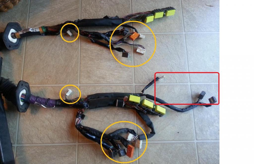
Two same body plugs from different SC300 doesn't necessarily mean that they have the same pins / wirings.
Observe pin 13 of Body Plug IJ1 ( I have previously posted the different common body plugs so you get familiar with them since I will start mentioning them more and more from now on).
Pin 13 (I surely do hope you know how to identify pin numbers on a plug by now ) on the left is empty and Pin 13 on the right it is occupied and yet these are both from an SC300 . So depending on your model year , wirings / pinnings can be different.
The wiring diagrams of the particular year and model of car you are working on will be your best friend. And with the Internet now a days , I can almost guarantee you , somewhere somehow you can find a copy of such wiring diagram. Research ... Research ... Research is the keyword.
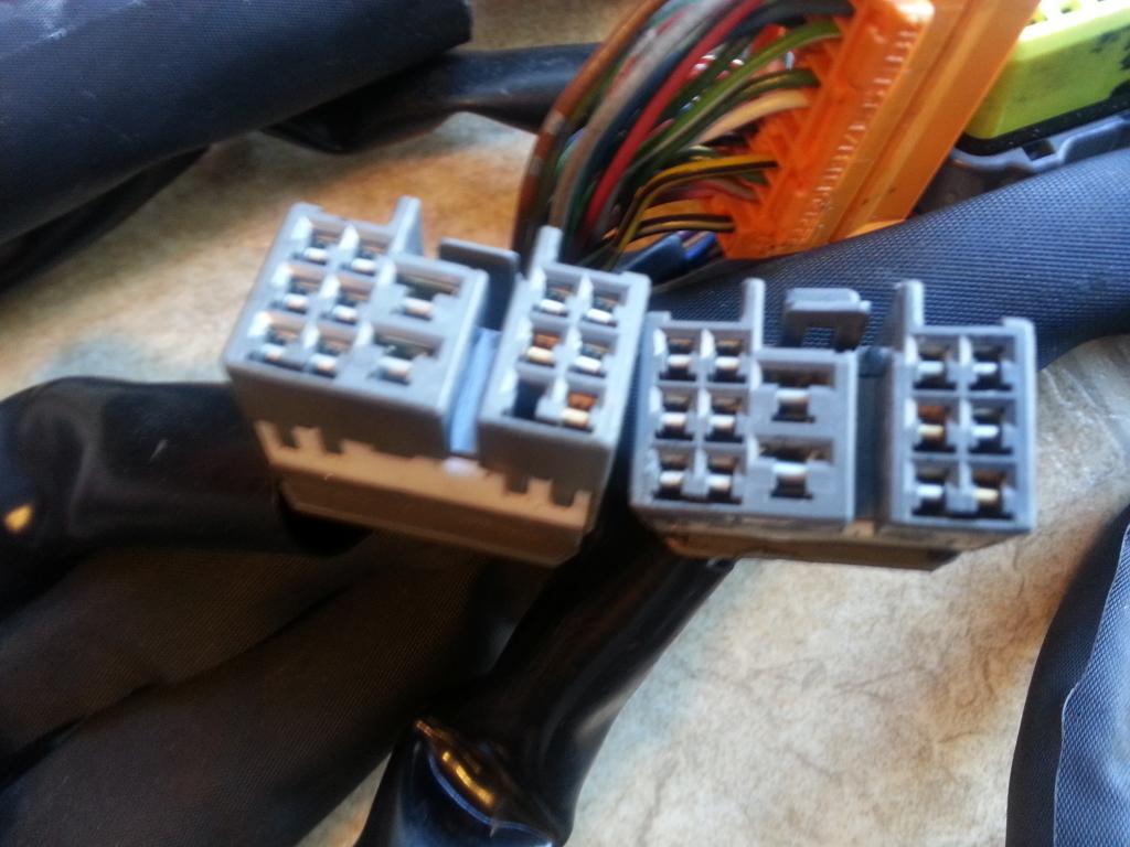
I am telling you all these not to discourage you and say Oh crap this is getting harder ! NO IT IS NOT . I am just mentioning that there maybe differences on body plugs. Bottom line , you need the actual original engine harness of the car you want to swap a 2jzgte so you can extract those plugs you will merge into the Aristo 2jzgte harness. Do not just grab let's say any SC300 body plugs and merge them into the harness you are building. I am not saying that wouldn't work. In fact more likely it would. But I am just trying to avoid the possibility of missing something.
To further emphasize my point ... let me add into the mix an SC400 engine harness
The top one is from an SC400 engine harness. It has same common body plugs but may have extra as shown on the red square . So not all SC300/SC400 have exactly the same plugs. Extract them if possible from the actual car for which you are making the 2jzgte wiring harness
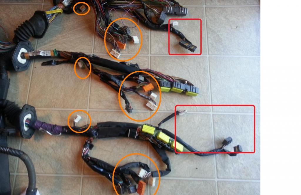

Last edited by gerrb; 02-01-14 at 05:35 AM.