2JZGTE Wiring Harness Made Easy
 01-31-14, 03:16 PM
#31

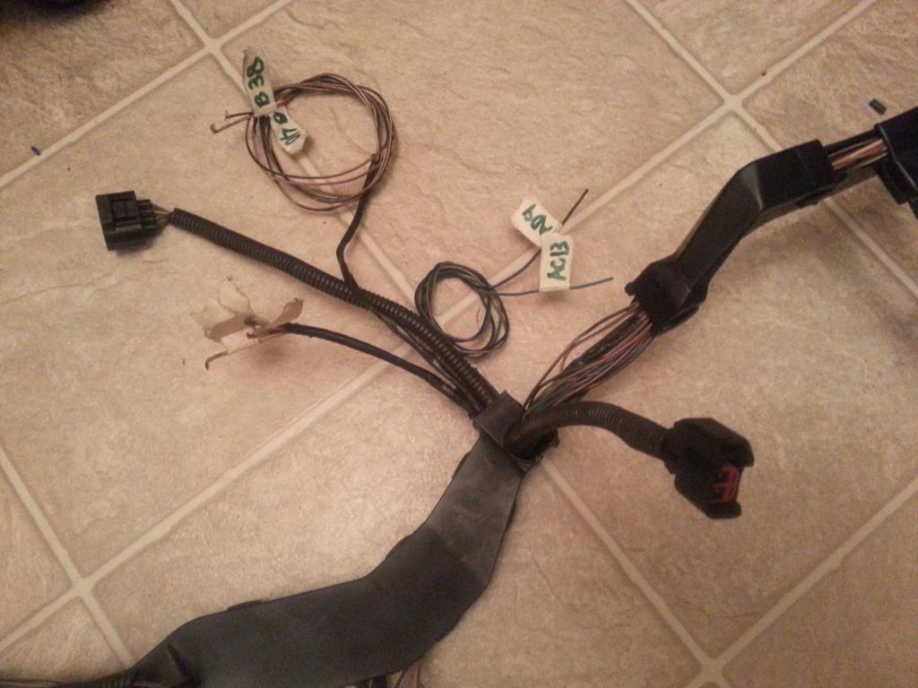
On the two harnesses I am working on I kept the Water Temperature Gauge Sender , Water Temperature Coolant Sensor and Crankshaft Position Sensor Connectors .
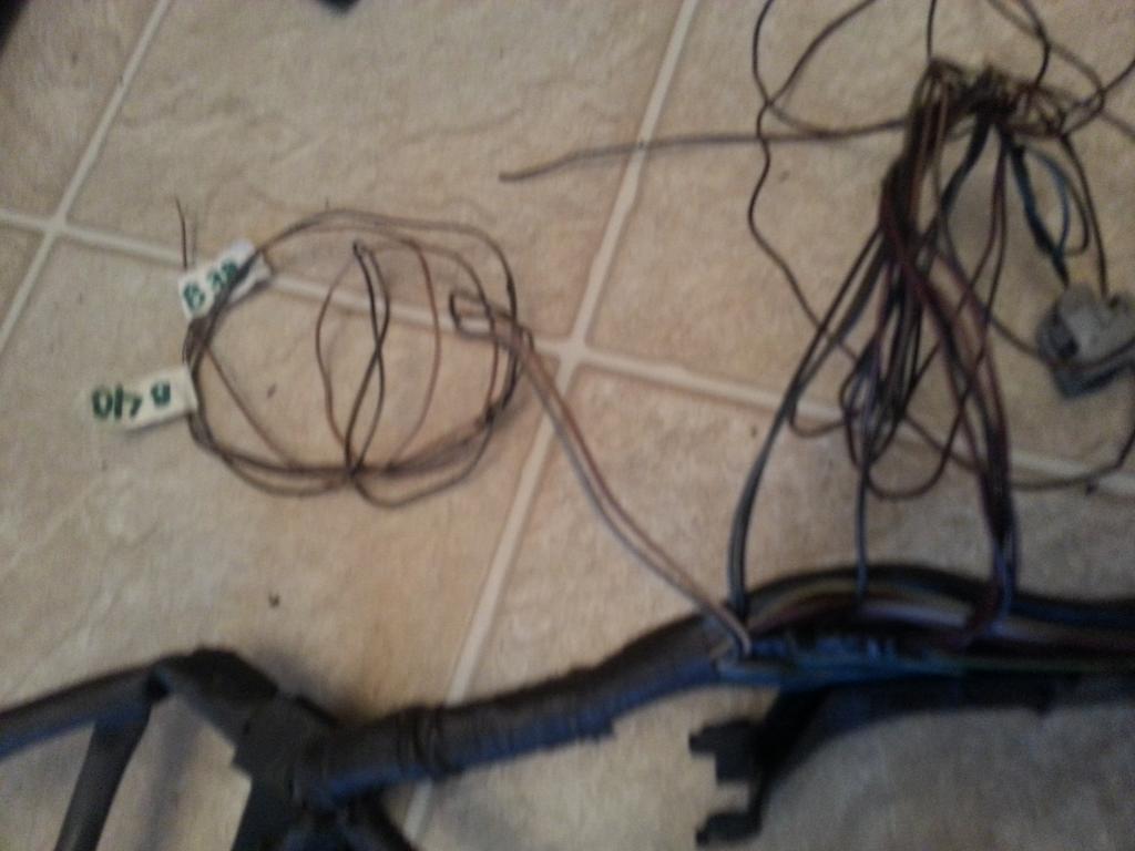
For Aaron's harness , the 2 VSVs and Hydraulic Fan Solenoid Connectors were taken out but the wires were kept as extra wires for future use.
I had to label those wires from Pin 39 and Pin 60 just to make sure I know what they are for and would find their counter part on the other end easily and rolled them with their B+ wires. Remember VSV wires always come in pair. One goes to the 80 pin ECU Connector and the other is a common B+ (voltage) supply.
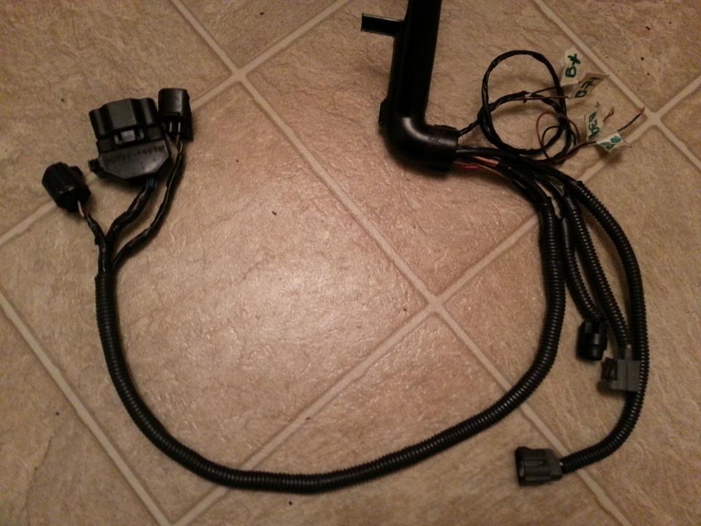
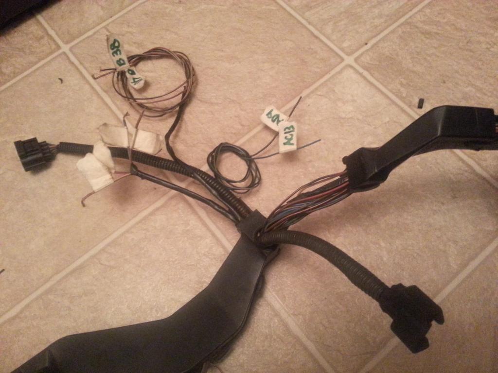
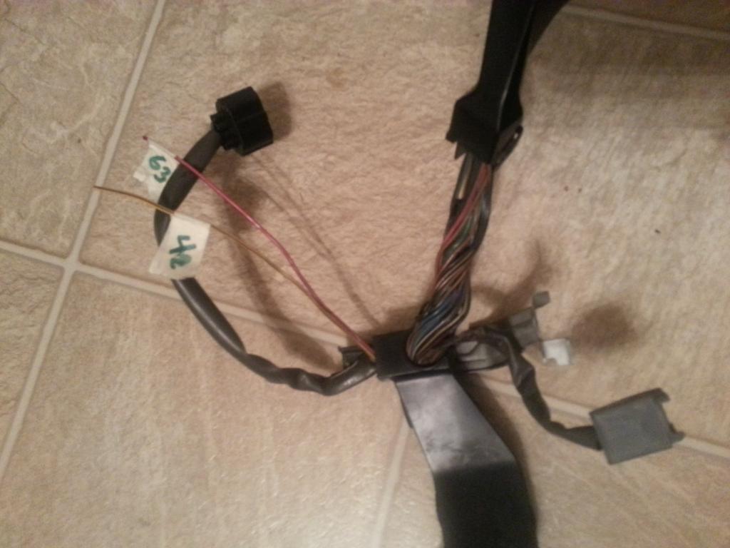
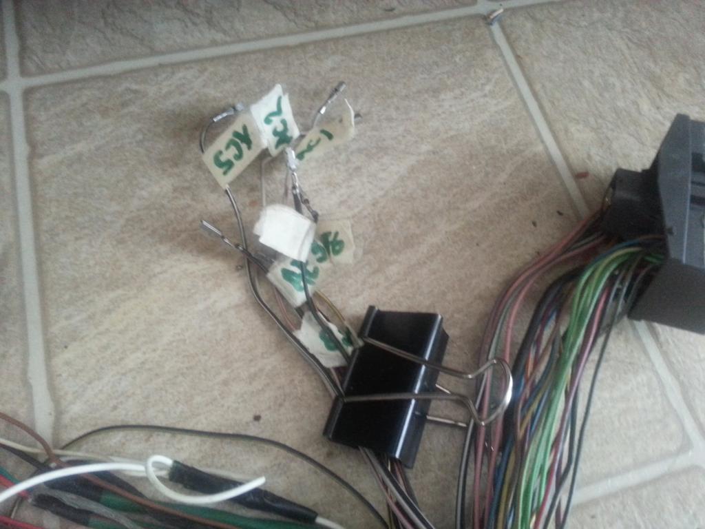
So from that part of the harness , I pulled the connector we previously labeled #6 out up to the point where I took out the covers and wraps. Now you see it on the left side of he picture
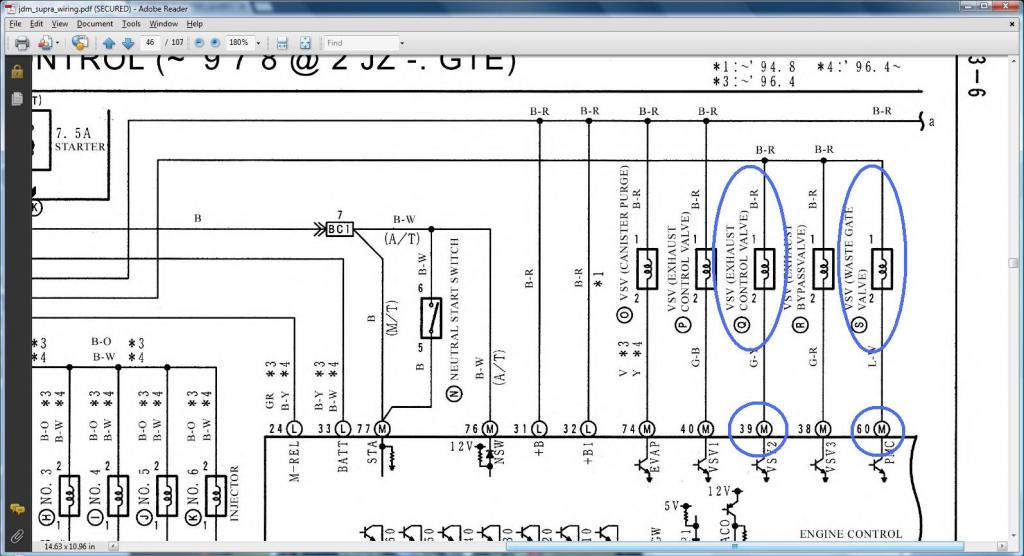
VSV wires are always pairs. One goes to the 80 pin ECU and the other are all T'ed. On the pictures below you see the 39 & 60 labeled . Their pairs I have to take them out.
I had to pull out too that wire I labeled 48 from the oxygen sensor . I don't need it there.
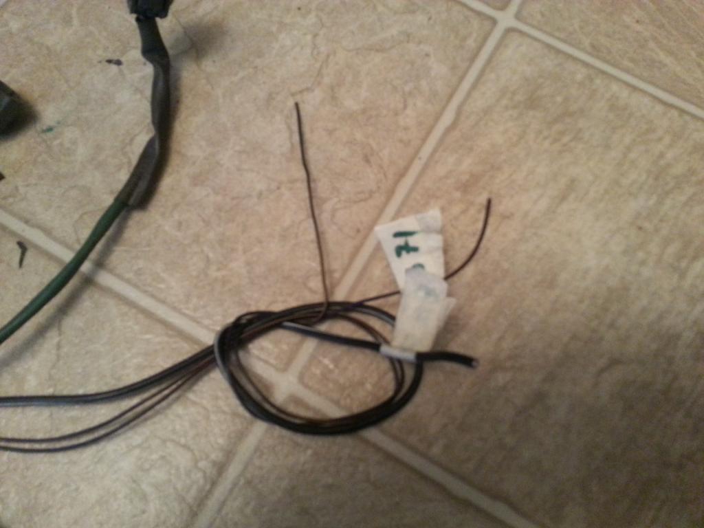
On the left of the picture you see those B+ wires from the VSVs (their Pin 1) pulled out also and rolled together with all the other wires that are being taken out of the harness ..
Looking at your chart , you know that all those VSVs' pin 1 were all connected together ...and here they are physically. You see the electrical tape where they were joined ?
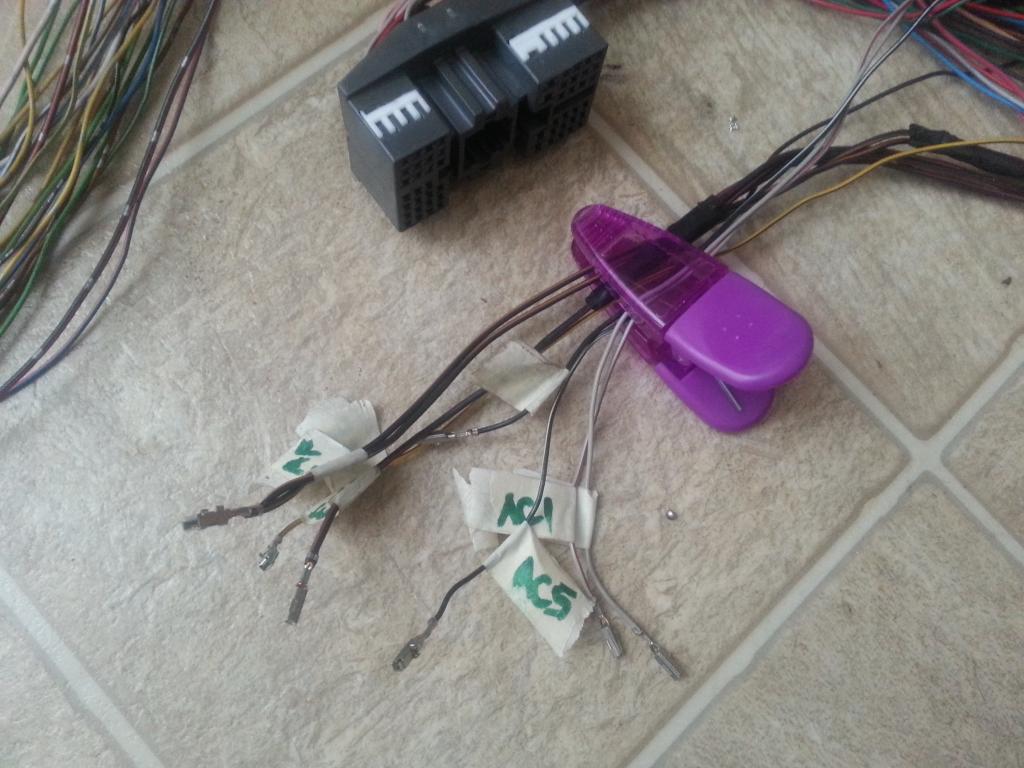
Moved those VSV (pins 38 and 40) wires to the area where I am using them . I will used them for the Air Intake Temp Sensor installed after the Intercooler.
Installed back my covers on that area just to prevent those wires being all over the place and did cut all those T'ed B+ (voltage) supply lines of the VSVs .
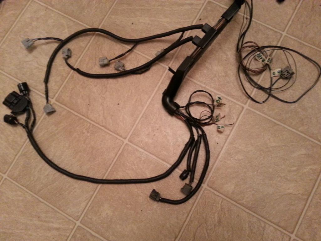
So after doing THE DRILL, this is what I got for Aaron's harness
So up to this point of the 2jzgte harness build for Aaron's car , this is what we have finished so far ...
For Aaron's harness , the 2 VSVs and Hydraulic Fan Solenoid Connectors were taken out but the wires were kept as extra wires for future use.
I had to label those wires from Pin 39 and Pin 60 just to make sure I know what they are for and would find their counter part on the other end easily and rolled them with their B+ wires. Remember VSV wires always come in pair. One goes to the 80 pin ECU Connector and the other is a common B+ (voltage) supply.

So from that part of the harness , I pulled the connector we previously labeled #6 out up to the point where I took out the covers and wraps. Now you see it on the left side of he picture

VSV wires are always pairs. One goes to the 80 pin ECU and the other are all T'ed. On the pictures below you see the 39 & 60 labeled . Their pairs I have to take them out.


I had to pull out too that wire I labeled 48 from the oxygen sensor . I don't need it there.

On the left of the picture you see those B+ wires from the VSVs (their Pin 1) pulled out also and rolled together with all the other wires that are being taken out of the harness ..


Looking at your chart , you know that all those VSVs' pin 1 were all connected together ...and here they are physically. You see the electrical tape where they were joined ?

Moved those VSV (pins 38 and 40) wires to the area where I am using them . I will used them for the Air Intake Temp Sensor installed after the Intercooler.

Installed back my covers on that area just to prevent those wires being all over the place and did cut all those T'ed B+ (voltage) supply lines of the VSVs .

So after doing THE DRILL, this is what I got for Aaron's harness


So up to this point of the 2jzgte harness build for Aaron's car , this is what we have finished so far ...

 01-31-14, 03:17 PM
#32
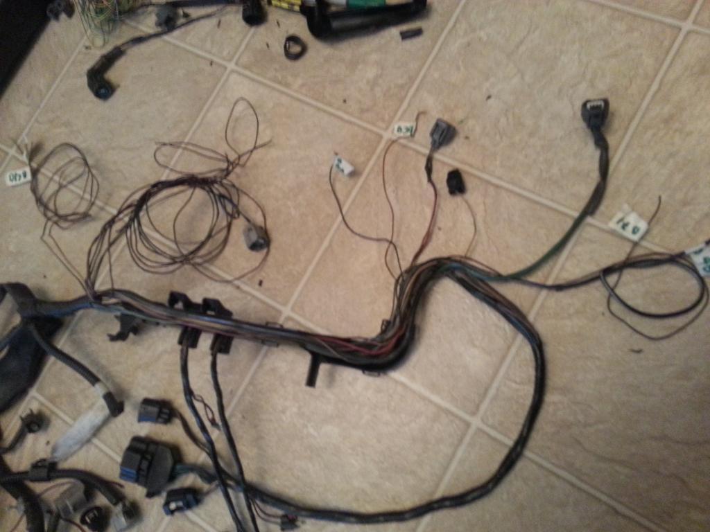
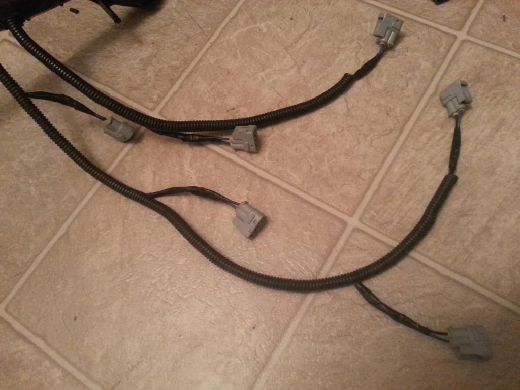
Now let me show what I did on the second harness I was working on. Remember this harness will be like stock just to help those doing a stock swap.
I am keeping all the plugs in that area that means including the VSVs except the hydraulic fan solenoid but am keeping its wires as extra wires for future use. I didn't need the Oxygen Sensor signal wire in that area so I have to pull it out.
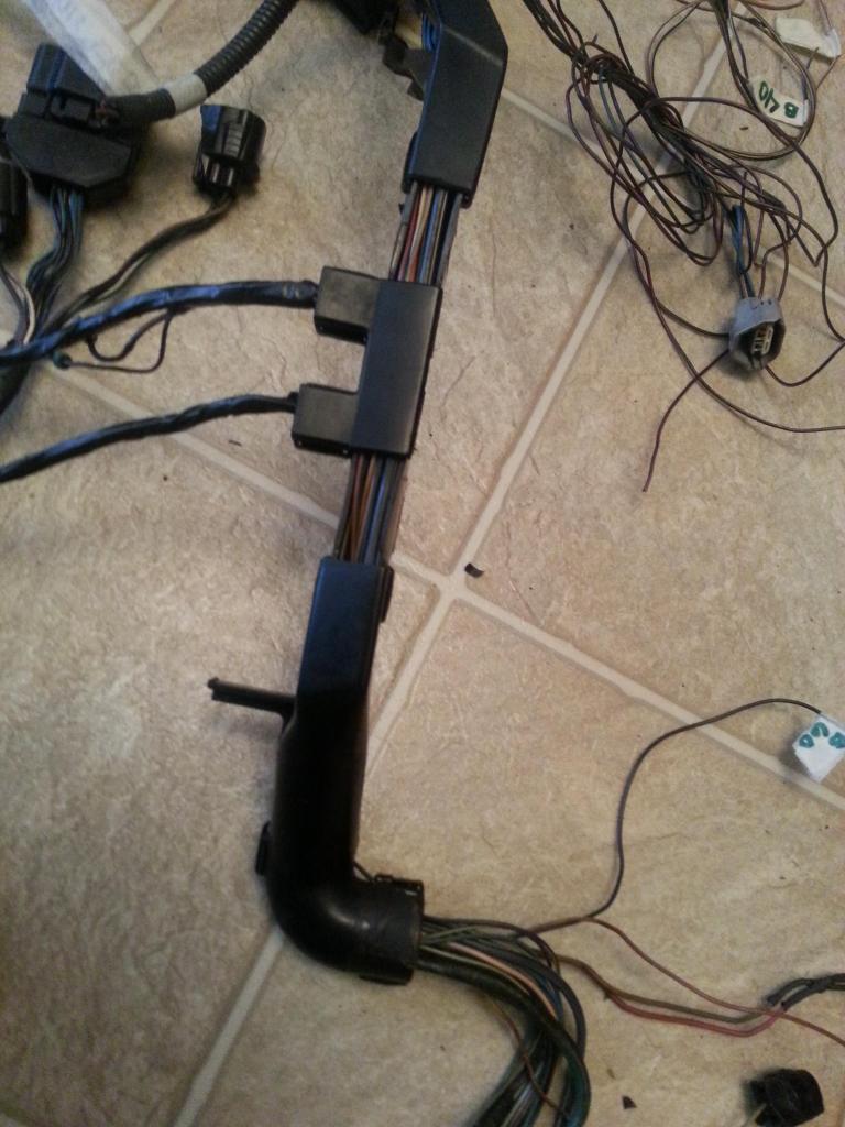
At this point I have done THE DRILL on every plug on this area. Plugs that are broken were replaced. Wires that needed to be extended were extended . You know how that drill was to suppose to go so I won't tell you the rest .
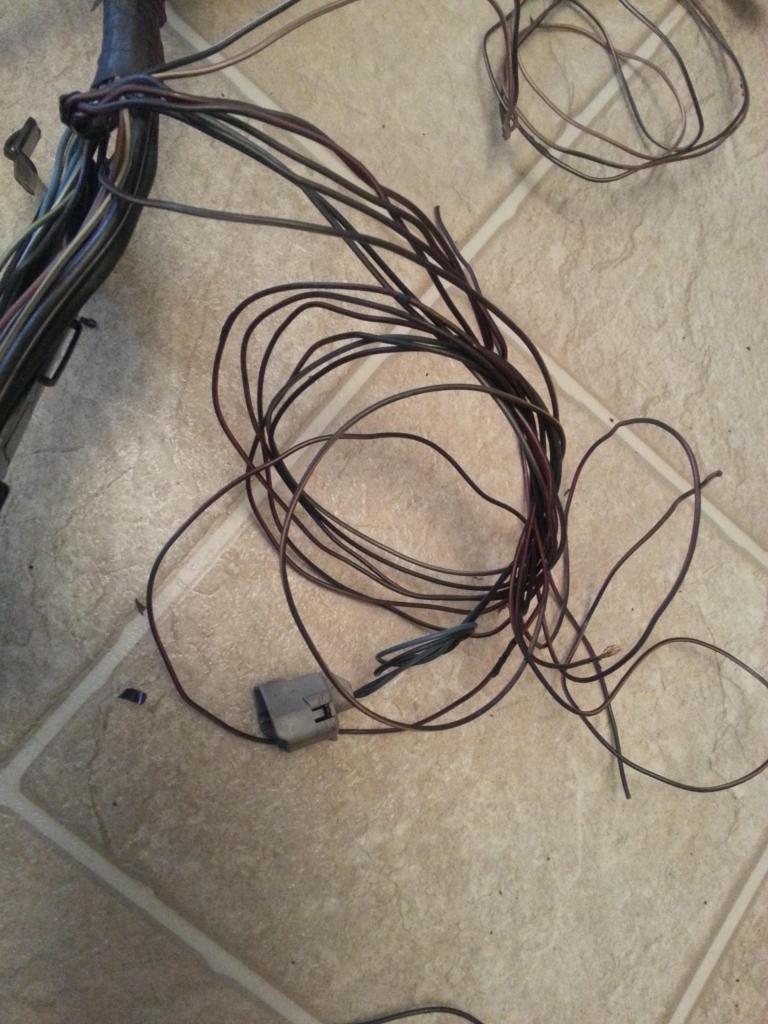
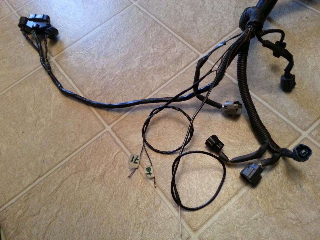
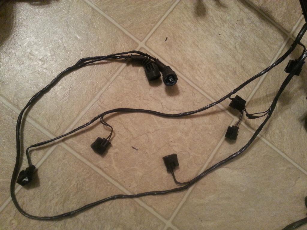
Took out those brittle wraps , about to cut the hydraulic fan solenoid plug since I have labeled the wires where they come from. The only wire I have to pull out from this area is that shielded wire from the oxygen sensor that goes to Pin 48 of the 80 pin ECU Connector. You see it right there at the back rolled and would be pulled out as soon as I take out those covers.
This is where I am right now for my second harness. That O2 sensor wire pulled out as you can see it on the top right of the picture . I have two sets of extra wires. One set has the B+ so it can be used for my Boost Solenoid in that area if I am on an aftermarket turbo. The extra set of wires goes straight to the ECU end connectors and can be used for future upgrades. All the other plugs remain the same . That means this harness I can use for stock 2jzgte swap. As I have said , I don't have any corrugated flexible hose so it is not wrapped yet.
I am keeping all the plugs in that area that means including the VSVs except the hydraulic fan solenoid but am keeping its wires as extra wires for future use. I didn't need the Oxygen Sensor signal wire in that area so I have to pull it out.

At this point I have done THE DRILL on every plug on this area. Plugs that are broken were replaced. Wires that needed to be extended were extended . You know how that drill was to suppose to go so I won't tell you the rest .
Took out those brittle wraps , about to cut the hydraulic fan solenoid plug since I have labeled the wires where they come from. The only wire I have to pull out from this area is that shielded wire from the oxygen sensor that goes to Pin 48 of the 80 pin ECU Connector. You see it right there at the back rolled and would be pulled out as soon as I take out those covers.

This is where I am right now for my second harness. That O2 sensor wire pulled out as you can see it on the top right of the picture . I have two sets of extra wires. One set has the B+ so it can be used for my Boost Solenoid in that area if I am on an aftermarket turbo. The extra set of wires goes straight to the ECU end connectors and can be used for future upgrades. All the other plugs remain the same . That means this harness I can use for stock 2jzgte swap. As I have said , I don't have any corrugated flexible hose so it is not wrapped yet.
 01-31-14, 03:20 PM
#33
Let us update our CHART
80 PIN ECU CONNECTOR
1
2
7 <--> Pin 2 of the Crankshaft Position Sensor CHECKED
10
20
27 <--> Pin 1 of the Crankshaft Position Sensor CHECKED
30
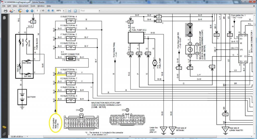
38 <--> Pin 2 of the VSV3 CHECKED
39 <--> Pin 2 of the VSV2 CHECKED
40 <--> Pin 2 of the VSV1 CHECKED
44 <--> Pin 2 of the Water Temperature Sensor CHECKED
48 <--> Pin 3 of the O2 Sensor CHECKED
50
51
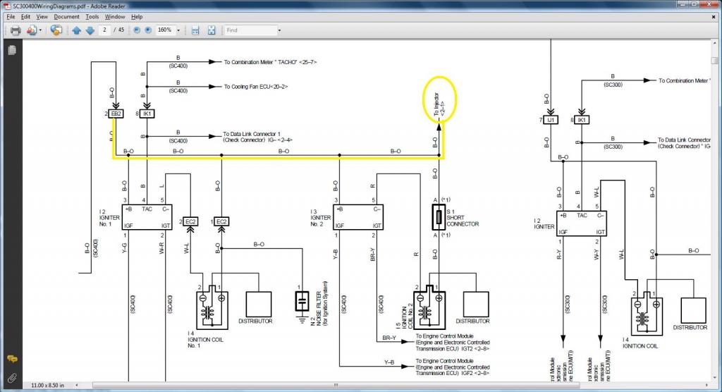
52 <--> Pin 7 of the 12 pin Igniter Connector CHECKED
53 <--> Pin 8 of the 12 pin igniter Connector CHECKED
54 <--> Pin 9 of the 12 pin igniter Connector CHECKED
55 <--> Pin 3 of the 12 pin igniter Connector CHECKED
56 <--> Pin 2 of the 12 pin Igniter Connector CHECKED
57 <--> Pin 1 of the 12 pin Igniter Connector CHECKED
58 <--> Pin 3 of the 4 pin Igniter Connector CHECKED
59
60 <--> Pin 2 of the VSVPMC CHECKED
65 <--> Pin 1 of the Water Temperature Sensor CHECKED
70
71 <--> Pin 1 of the O2 Sensor CHECKED
80
4 PIN IGNITER CONNECTOR
1 <--> Pin 12 of Plug F of Aristo plug <--> ( Pin 19 of the Data Link Connector <--> ( SC3 IK1-8 , SC4 IK1-8 , MK4 ))
2 <--> Pin 6 of Plug F of Aristo plug <--> Pin 1 of the Noise Filter <--> ( SC3 IJ1-7 , SC4 EB2-2 , MK4 IJ1-1 or IJ1-9 )
3 <--> Pin 58 of the 80 pin ECU connector CHECKED
4 <--> Ground Connector on the Front Side of Intake Manifold <--> Pin 2 of the Noise filter Connector CHECKED
12 PIN IGNITER CONNECTOR
1 <--> Pin 57 of the 80 pin ECU connector CHECKED
2 <--> Pin 56 of the 80 pin ECU connector CHECKED
3 <--> Pin 55 of the 80 pin ECU connector CHECKED
4 <--> Pin 2 of the Ignition Coil Connector 3 CHECKED
5 <--> Pin 2 of the Ignition Coil Connector 2 CHECKED
6 <--> Pin 2 of the Ignition Coil Connector 1 CHECKED
7 <--> Pin 52 of the 80 pin ECU connector CHECKED
8 <--> Pin 53 of the 80 pin ECU connector CHECKED
9 <--> Pin 54 of the 80 pin ECU connector CHECKED
10 <--> Pin 2 of the Ignition Coil Connector 4 CHECKED
11 <--> Pin 2 of the Ignition Coil Connector 5 CHECKED
12 <--> Pin 2 of the Ignition Coil Connector 6 CHECKED
CRANKSHAFT POSITION SENSOR
1 <--> Pin 27 of the 80 pin ECU Connector CHECKED
2 <--> Pin 7 of the 80 pin ECU Connector CHECKED
IGNITION COIL 1
1 <--> Pin 1 of the Noise Filter <--> Pin 2 of the 4 pin Igniter Connector <--> Pin 1 of Ignition Coil 2,3,4,5,6 <-->( SC3 IJ1-7 , SC4 EB2-2 , MK4 IJ1-1 or IJ1-9 )
2 <--> Pin 6 of the 12 Pin Igniter Connector CHECKED
IGNITION COIL 2
1 <--> Pin 1 of the Noise Filter <--> Pin 2 of the 4 pin Igniter Connector <--> Pin 1 of Ignition Coil 1,3,4,5,6 <-->( SC3 IJ1-7 , SC4 EB2-2 , MK4 IJ1-1 or IJ1-9 )
2 <--> Pin 5 of the 12 Pin Igniter Connector CHECKED
IGNITION COIL 3
1 <--> Pin 1 of the Noise Filter <--> Pin 2 of the 4 pin Igniter Connector <--> Pin 1 of Ignition Coil 1,2,4,5,6 <-->( SC3 IJ1-7 , SC4 EB2-2 , MK4 IJ1-1 or IJ1-9 )
2 <--> Pin 4 of the 12 Pin Igniter Connector CHECKED
IGNITION COIL 4
1 <--> Pin 1 of the Noise Filter <--> Pin 2 of the 4 pin Igniter Connector <--> Pin 1 of Ignition Coil 1,2,3,5,6 <-->( SC3 IJ1-7 , SC4 EB2-2 , MK4 IJ1-1 or IJ1-9 )
2 <--> Pin 10 of the 12 Pin Igniter Connector CHECKED
IGNITION COIL 5
1 <--> Pin 1 of the Noise Filter <--> Pin 2 of the 4 pin Igniter Connector <--> Pin 1 of Ignition Coil 1,2,3,4,6 <-->( SC3 IJ1-7 , SC4 EB2-2 , MK4 IJ1-1 or IJ1-9 )
2 <--> Pin 11 of the 12 Pin Igniter Connector CHECKED
IGNITION COIL 6
1 <--> Pin 1 of the Noise Filter <--> Pin 2 of the 4 pin Igniter Connector <--> Pin 1 of Ignition Coil 1,2,3,4,5 <-->( SC3 IJ1-7 , SC4 EB2-2 , MK4 IJ1-1 or IJ1-9 )
2 <--> Pin 12 of the 12 Pin Igniter Connector CHECKED
NOISE FILTER
1 <--> Pin 2 of the 4 pin Igniter Connector <--> ( SC3 IJ1-7, SC4 EB2-2 , MK4 IJ1-1 or IJ1-9 )
2 <--> Ground Connector on the Front Side of Intake Manifold <--> Pin 4 of the 4 pin Igniter Connector CHECKED
WATER TEMPERATURE SENSOR
1 <--> Pin 65 of the 80 pin ECU Connector CHECKED
2 <--> Pin 44 of the 80 pin ECU Connector CHECKED
WATER TEMPERATURE GAUGE SENDER
1 <--> Pin 9 of Plug F of the Big Gray Aristo Plug (should go to SC3 IK1-9 , SC4 IK1-9 & Short-3 , MK4 II1-19 )
The following plugs are necessary only if you are going stock 2jzgte setup
OXYGEN SENSOR (O2)
1 <--> Pin 71 of the 80 pin ECU Connector CHECKED
2 <--> Pin 3 of Plug E of Aristo Plug <-> (Pin 12 of the Data Link Connector <--> ( SC3 IJ1-12 & EB2-1 & Short-4 , SC4 IJ1-12 & EB2-3 , MK4 EA3-3 ))
3 <--> Pin 48 of the 80 pin ECU Connector CHECKED
VSV1 ( Air Intake Control Valve )
1 <--> Pin 2 of the O2 Sensor <--> Pin 1 of the VSV3 <-> (Pin 12 of the Data Link Connector <--> ( SC3 IJ1-12 & EB2-1 & Short-4 , SC4 IJ1-12 & EB2-3 , MK4 EA3-3 ))
2 <--> Pin 40 of the 80 pin ECU Connector CHECKED
VSV2 ( Exhaust Control Valve )
1 <--> Pin 1 of VSV1 , VSV3 , VSVPMC <--> Pin 2 of the O2 Sensor <--> Pin 1 of the VSV3 <-> (Pin 12 of the Data Link Connector <--> ( SC3 IJ1-12 & EB2-1 & Short-4 , SC4 IJ1-12 & EB2-3 , MK4 EA3-3 ))
2 <--> Pin 39 of the 80 pin ECU Connector CHECKED
VSV3( Exhaust Bypass Valve )
1 <--> Pin 2 of the O2 Sensor <-->Pin 1 of the VSV1 <-> (Pin 12 of the Data Link Connector <--> ( SC3 IJ1-12 & EB2-1 & Short-4 , SC4 IJ1-12 & EB2-3 , MK4 EA3-3 ))
2 <--> Pin 38 of the 80 pin ECU Connector CHECKED
VSVPMC ( Waste Gate Valve )
1 <--> Pin 1 of VSV1 , VSV2 , VSV3 <--> Pin 2 of the O2 Sensor <--> Pin 1 of the VSV3 <-> (Pin 12 of the Data Link Connector <--> ( SC3 IJ1-12 & EB2-1 & Short-4 , SC4 IJ1-12 & EB2-3 , MK4 EA3-3 ))
2 <--> Pin 60 of the 80 pin ECU Connector CHECKED
The following plugs needs to be taken out
BIG GRAY ARISTO PLUG
PLUG C
13 <--> Extra Wire for future use
PLUG D
9 <--> Extra Wire for future use
PLUG E
3 <--> Pin 2 of Oxygen Sensor <--> (Pin 12 of the Data Link Connector <--> ( SC3 IJ1-12 & EB2-1 & Short-4 , SC4 IJ1-12 & EB2-3 , MK4 EA3-3 ))
PLUG F
6 <--> Pin 1 of the Noise Filter <--> ( SC3 IJ1-7 , SC4 EB2-2 , MK4 IJ1-1 or IJ1-9 )
9 <--> Pin 1 of the Water Temperature Gauge Sender <--> ( SC3 IK1-9 , SC4 IK1-9 & Short-3 , MK4 II1-19 )
12 <--> ( Pin 19 of the Data Link Connector & to ( SC3 IK1-8 , SC4 IK1-8 , MK4 ))
80 PIN ECU CONNECTOR
1
2
7 <--> Pin 2 of the Crankshaft Position Sensor CHECKED
10
20
27 <--> Pin 1 of the Crankshaft Position Sensor CHECKED
30
38 <--> Pin 2 of the VSV3 CHECKED
39 <--> Pin 2 of the VSV2 CHECKED
40 <--> Pin 2 of the VSV1 CHECKED
44 <--> Pin 2 of the Water Temperature Sensor CHECKED
48 <--> Pin 3 of the O2 Sensor CHECKED
50
51
52 <--> Pin 7 of the 12 pin Igniter Connector CHECKED
53 <--> Pin 8 of the 12 pin igniter Connector CHECKED
54 <--> Pin 9 of the 12 pin igniter Connector CHECKED
55 <--> Pin 3 of the 12 pin igniter Connector CHECKED
56 <--> Pin 2 of the 12 pin Igniter Connector CHECKED
57 <--> Pin 1 of the 12 pin Igniter Connector CHECKED
58 <--> Pin 3 of the 4 pin Igniter Connector CHECKED
59
60 <--> Pin 2 of the VSVPMC CHECKED
65 <--> Pin 1 of the Water Temperature Sensor CHECKED
70
71 <--> Pin 1 of the O2 Sensor CHECKED
80
4 PIN IGNITER CONNECTOR
1 <--> Pin 12 of Plug F of Aristo plug <--> ( Pin 19 of the Data Link Connector <--> ( SC3 IK1-8 , SC4 IK1-8 , MK4 ))
2 <--> Pin 6 of Plug F of Aristo plug <--> Pin 1 of the Noise Filter <--> ( SC3 IJ1-7 , SC4 EB2-2 , MK4 IJ1-1 or IJ1-9 )
3 <--> Pin 58 of the 80 pin ECU connector CHECKED
4 <--> Ground Connector on the Front Side of Intake Manifold <--> Pin 2 of the Noise filter Connector CHECKED
12 PIN IGNITER CONNECTOR
1 <--> Pin 57 of the 80 pin ECU connector CHECKED
2 <--> Pin 56 of the 80 pin ECU connector CHECKED
3 <--> Pin 55 of the 80 pin ECU connector CHECKED
4 <--> Pin 2 of the Ignition Coil Connector 3 CHECKED
5 <--> Pin 2 of the Ignition Coil Connector 2 CHECKED
6 <--> Pin 2 of the Ignition Coil Connector 1 CHECKED
7 <--> Pin 52 of the 80 pin ECU connector CHECKED
8 <--> Pin 53 of the 80 pin ECU connector CHECKED
9 <--> Pin 54 of the 80 pin ECU connector CHECKED
10 <--> Pin 2 of the Ignition Coil Connector 4 CHECKED
11 <--> Pin 2 of the Ignition Coil Connector 5 CHECKED
12 <--> Pin 2 of the Ignition Coil Connector 6 CHECKED
CRANKSHAFT POSITION SENSOR
1 <--> Pin 27 of the 80 pin ECU Connector CHECKED
2 <--> Pin 7 of the 80 pin ECU Connector CHECKED
IGNITION COIL 1
1 <--> Pin 1 of the Noise Filter <--> Pin 2 of the 4 pin Igniter Connector <--> Pin 1 of Ignition Coil 2,3,4,5,6 <-->( SC3 IJ1-7 , SC4 EB2-2 , MK4 IJ1-1 or IJ1-9 )
2 <--> Pin 6 of the 12 Pin Igniter Connector CHECKED
IGNITION COIL 2
1 <--> Pin 1 of the Noise Filter <--> Pin 2 of the 4 pin Igniter Connector <--> Pin 1 of Ignition Coil 1,3,4,5,6 <-->( SC3 IJ1-7 , SC4 EB2-2 , MK4 IJ1-1 or IJ1-9 )
2 <--> Pin 5 of the 12 Pin Igniter Connector CHECKED
IGNITION COIL 3
1 <--> Pin 1 of the Noise Filter <--> Pin 2 of the 4 pin Igniter Connector <--> Pin 1 of Ignition Coil 1,2,4,5,6 <-->( SC3 IJ1-7 , SC4 EB2-2 , MK4 IJ1-1 or IJ1-9 )
2 <--> Pin 4 of the 12 Pin Igniter Connector CHECKED
IGNITION COIL 4
1 <--> Pin 1 of the Noise Filter <--> Pin 2 of the 4 pin Igniter Connector <--> Pin 1 of Ignition Coil 1,2,3,5,6 <-->( SC3 IJ1-7 , SC4 EB2-2 , MK4 IJ1-1 or IJ1-9 )
2 <--> Pin 10 of the 12 Pin Igniter Connector CHECKED
IGNITION COIL 5
1 <--> Pin 1 of the Noise Filter <--> Pin 2 of the 4 pin Igniter Connector <--> Pin 1 of Ignition Coil 1,2,3,4,6 <-->( SC3 IJ1-7 , SC4 EB2-2 , MK4 IJ1-1 or IJ1-9 )
2 <--> Pin 11 of the 12 Pin Igniter Connector CHECKED
IGNITION COIL 6
1 <--> Pin 1 of the Noise Filter <--> Pin 2 of the 4 pin Igniter Connector <--> Pin 1 of Ignition Coil 1,2,3,4,5 <-->( SC3 IJ1-7 , SC4 EB2-2 , MK4 IJ1-1 or IJ1-9 )
2 <--> Pin 12 of the 12 Pin Igniter Connector CHECKED
NOISE FILTER
1 <--> Pin 2 of the 4 pin Igniter Connector <--> ( SC3 IJ1-7, SC4 EB2-2 , MK4 IJ1-1 or IJ1-9 )
2 <--> Ground Connector on the Front Side of Intake Manifold <--> Pin 4 of the 4 pin Igniter Connector CHECKED
WATER TEMPERATURE SENSOR
1 <--> Pin 65 of the 80 pin ECU Connector CHECKED
2 <--> Pin 44 of the 80 pin ECU Connector CHECKED
WATER TEMPERATURE GAUGE SENDER
1 <--> Pin 9 of Plug F of the Big Gray Aristo Plug (should go to SC3 IK1-9 , SC4 IK1-9 & Short-3 , MK4 II1-19 )
The following plugs are necessary only if you are going stock 2jzgte setup
OXYGEN SENSOR (O2)
1 <--> Pin 71 of the 80 pin ECU Connector CHECKED
2 <--> Pin 3 of Plug E of Aristo Plug <-> (Pin 12 of the Data Link Connector <--> ( SC3 IJ1-12 & EB2-1 & Short-4 , SC4 IJ1-12 & EB2-3 , MK4 EA3-3 ))
3 <--> Pin 48 of the 80 pin ECU Connector CHECKED
VSV1 ( Air Intake Control Valve )
1 <--> Pin 2 of the O2 Sensor <--> Pin 1 of the VSV3 <-> (Pin 12 of the Data Link Connector <--> ( SC3 IJ1-12 & EB2-1 & Short-4 , SC4 IJ1-12 & EB2-3 , MK4 EA3-3 ))
2 <--> Pin 40 of the 80 pin ECU Connector CHECKED
VSV2 ( Exhaust Control Valve )
1 <--> Pin 1 of VSV1 , VSV3 , VSVPMC <--> Pin 2 of the O2 Sensor <--> Pin 1 of the VSV3 <-> (Pin 12 of the Data Link Connector <--> ( SC3 IJ1-12 & EB2-1 & Short-4 , SC4 IJ1-12 & EB2-3 , MK4 EA3-3 ))
2 <--> Pin 39 of the 80 pin ECU Connector CHECKED
VSV3( Exhaust Bypass Valve )
1 <--> Pin 2 of the O2 Sensor <-->Pin 1 of the VSV1 <-> (Pin 12 of the Data Link Connector <--> ( SC3 IJ1-12 & EB2-1 & Short-4 , SC4 IJ1-12 & EB2-3 , MK4 EA3-3 ))
2 <--> Pin 38 of the 80 pin ECU Connector CHECKED
VSVPMC ( Waste Gate Valve )
1 <--> Pin 1 of VSV1 , VSV2 , VSV3 <--> Pin 2 of the O2 Sensor <--> Pin 1 of the VSV3 <-> (Pin 12 of the Data Link Connector <--> ( SC3 IJ1-12 & EB2-1 & Short-4 , SC4 IJ1-12 & EB2-3 , MK4 EA3-3 ))
2 <--> Pin 60 of the 80 pin ECU Connector CHECKED
The following plugs needs to be taken out
BIG GRAY ARISTO PLUG
PLUG C
13 <--> Extra Wire for future use
PLUG D
9 <--> Extra Wire for future use
PLUG E
3 <--> Pin 2 of Oxygen Sensor <--> (Pin 12 of the Data Link Connector <--> ( SC3 IJ1-12 & EB2-1 & Short-4 , SC4 IJ1-12 & EB2-3 , MK4 EA3-3 ))
PLUG F
6 <--> Pin 1 of the Noise Filter <--> ( SC3 IJ1-7 , SC4 EB2-2 , MK4 IJ1-1 or IJ1-9 )
9 <--> Pin 1 of the Water Temperature Gauge Sender <--> ( SC3 IK1-9 , SC4 IK1-9 & Short-3 , MK4 II1-19 )
12 <--> ( Pin 19 of the Data Link Connector & to ( SC3 IK1-8 , SC4 IK1-8 , MK4 ))
Last edited by gerrb; 06-03-14 at 07:43 AM.
01-31-14, 03:21 PM
#34
Now let me give you some tools to counter check what we have written about these plugs.
DIAGRAMS TO VERIFY PIN NUMBERING & WHERE THE WIRE GOES
*** VSVs ***
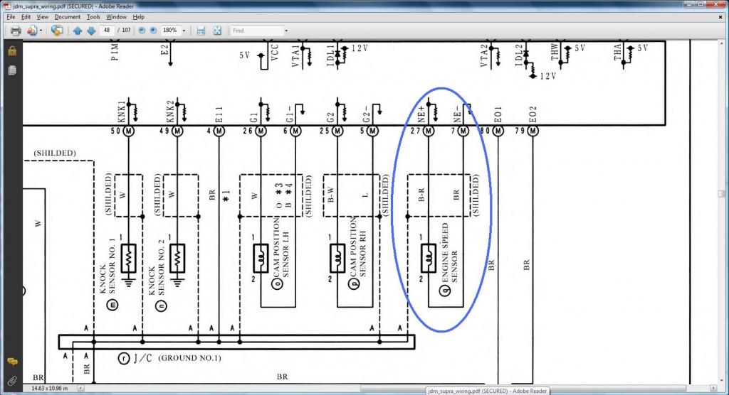
Crankshaft Position Sensor (Engine Speed Sensor on this Diagram)
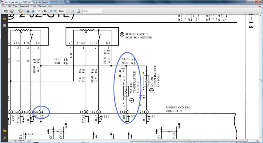
*** Water Temperature Sensor ***
DIAGRAMS TO VERIFY WHERE A WIRE SHOULD GO IN A SC300, SC400, MKIV
We don't have to prove that Pin 1 of VSV2 and VSVPMC should go to ( Pin 12 of the Data Link Connector & to ( SC3 IJ1-12 & EB2-1 & Short-4 , SC4 IJ1-12 & EB2-3 , MK4 EA3-3 )) Why ? It is because right from the start we have shown how Pin 2 of the Oxygen sensor goes to ( Pin 12 of the Data Link Connector & to ( SC3 IJ1-12 & EB2-1 & Short-4 , SC4 IJ1-12 & EB2-3 , MK4 EA3-3 )) . If you don't remember , go back to where we dealt with the Oxygen Sensor Plug. We also have shown previously that Pin 1 of VSV1 & VSV3 goes to Pin 2 of the Oxygen Sensor . On the diagram above you see Pin 1 of VSV2 and VSVPMC goes to Pin 1 of VSV1 & VSV3 . ERGO , Pin 1 of VSV2 & VSVPMC should go to ( Pin 12 of the Data Link Connector & to ( SC3 IJ1-12 & EB2-1 & Short-4 , SC4 IJ1-12 & EB2-3 , MK4 EA3-3 ))
 That sounds confusing right ?
  Then forget it !
  , you don't really need to know that.
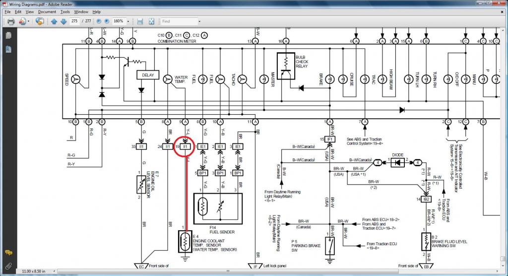
This is what we need to show , how do we know that Pin 1 of the Water Temperature Gauge Sender should go to ( SC3 IK1-9 , SC4 IK1-9 & Short-3 , MK4 II1-19 )
SC300 in yellow / SC400 in orange
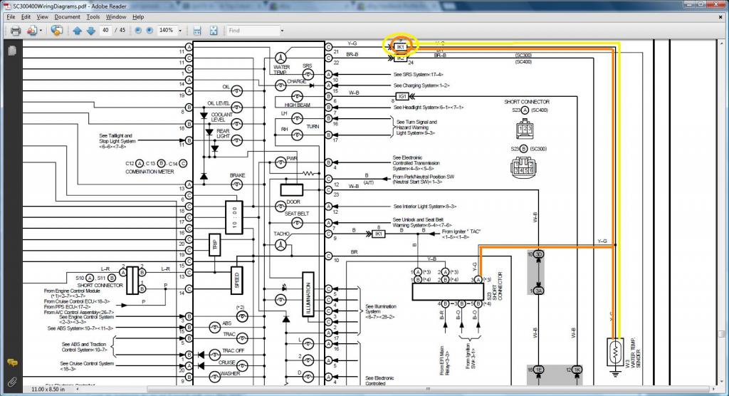
MKIV in red
DIAGRAMS TO VERIFY PIN NUMBERING & WHERE THE WIRE GOES
*** VSVs ***

Crankshaft Position Sensor (Engine Speed Sensor on this Diagram)

*** Water Temperature Sensor ***

DIAGRAMS TO VERIFY WHERE A WIRE SHOULD GO IN A SC300, SC400, MKIV
We don't have to prove that Pin 1 of VSV2 and VSVPMC should go to ( Pin 12 of the Data Link Connector & to ( SC3 IJ1-12 & EB2-1 & Short-4 , SC4 IJ1-12 & EB2-3 , MK4 EA3-3 )) Why ? It is because right from the start we have shown how Pin 2 of the Oxygen sensor goes to ( Pin 12 of the Data Link Connector & to ( SC3 IJ1-12 & EB2-1 & Short-4 , SC4 IJ1-12 & EB2-3 , MK4 EA3-3 )) . If you don't remember , go back to where we dealt with the Oxygen Sensor Plug. We also have shown previously that Pin 1 of VSV1 & VSV3 goes to Pin 2 of the Oxygen Sensor . On the diagram above you see Pin 1 of VSV2 and VSVPMC goes to Pin 1 of VSV1 & VSV3 . ERGO , Pin 1 of VSV2 & VSVPMC should go to ( Pin 12 of the Data Link Connector & to ( SC3 IJ1-12 & EB2-1 & Short-4 , SC4 IJ1-12 & EB2-3 , MK4 EA3-3 ))
That sounds confusing right ? Then forget it ! , you don't really need to know that.This is what we need to show , how do we know that Pin 1 of the Water Temperature Gauge Sender should go to ( SC3 IK1-9 , SC4 IK1-9 & Short-3 , MK4 II1-19 )
SC300 in yellow / SC400 in orange

MKIV in red

Last edited by gerrb; 01-31-14 at 03:28 PM.
01-31-14, 03:22 PM
#35
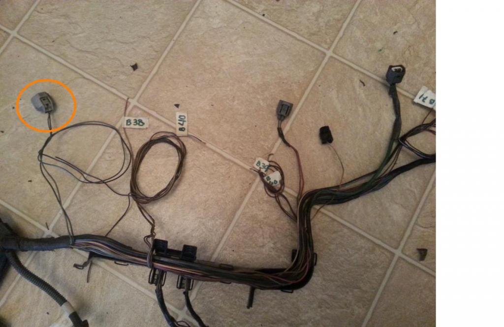
I hate to digress so much from the portion of the harness we are currently working on lest I create confusion . But allow me to throw this in here since someone mentioned body plugs.
My buddy Aaron (which I know wouldn't mind naming him as an example just to help others) works with electronics.... PCBs , PLCs .. what not . So you can't really say that electrical is something hard for him. He can read wiring diagrams . In fact I have given him all the wiring diagrams for the SC300 , SC400 and MKIV and what not . But being his first time in making a 2jzgte harness and all excited, happened to make a mistake and after that decided to give up on the harness. Having all the money in this world , he was ready to throw $1000 to buy a brand new harness. Aaron , I wish I had your bank accout , lmaol.
He thought , All he needed from the SC300 2jzge harness was the 40 pin ECU connector and the body plugs . This is what he did . He cut the harness to get just the body plugs and 40 pin connector.
You guys better be careful with your original engine harness , when you take out the body plugs. There are also some plugs that may be needed , plugs that do not end up in any component in the engine itself or on the car's ecu.
Let me give you an example. These plugs you see encircled are found on the SC300 / SC400 / MKIV harness below the fuse box. They are directly connected to the engine harness to supply power or connectivity to some other components . Aaron , you should have not cut that freaking harness.. .. peace buddy. !
Damn, now I don't remember what part of the harness build we are in.
My buddy Aaron (which I know wouldn't mind naming him as an example just to help others) works with electronics.... PCBs , PLCs .. what not . So you can't really say that electrical is something hard for him. He can read wiring diagrams . In fact I have given him all the wiring diagrams for the SC300 , SC400 and MKIV and what not . But being his first time in making a 2jzgte harness and all excited, happened to make a mistake and after that decided to give up on the harness. Having all the money in this world , he was ready to throw $1000 to buy a brand new harness. Aaron , I wish I had your bank accout , lmaol.
He thought , All he needed from the SC300 2jzge harness was the 40 pin ECU connector and the body plugs . This is what he did . He cut the harness to get just the body plugs and 40 pin connector.

You guys better be careful with your original engine harness , when you take out the body plugs. There are also some plugs that may be needed , plugs that do not end up in any component in the engine itself or on the car's ecu.
Let me give you an example. These plugs you see encircled are found on the SC300 / SC400 / MKIV harness below the fuse box. They are directly connected to the engine harness to supply power or connectivity to some other components . Aaron , you should have not cut that freaking harness..
.. peace buddy. ! 
Damn,
now I don't remember what part of the harness build we are in.
Last edited by gerrb; 01-31-14 at 03:35 PM.
01-31-14, 03:23 PM
#36
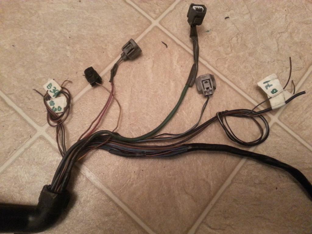
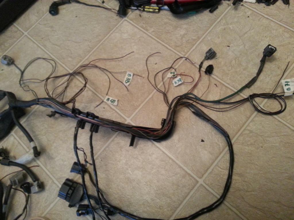
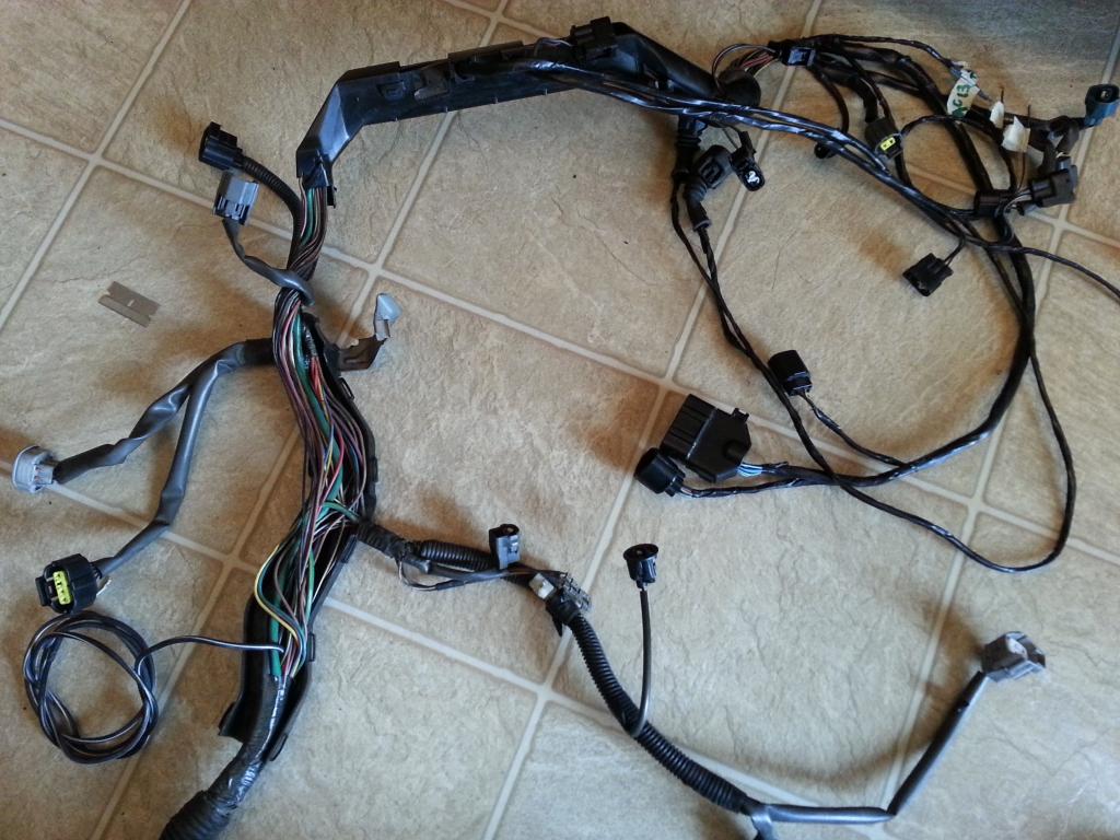
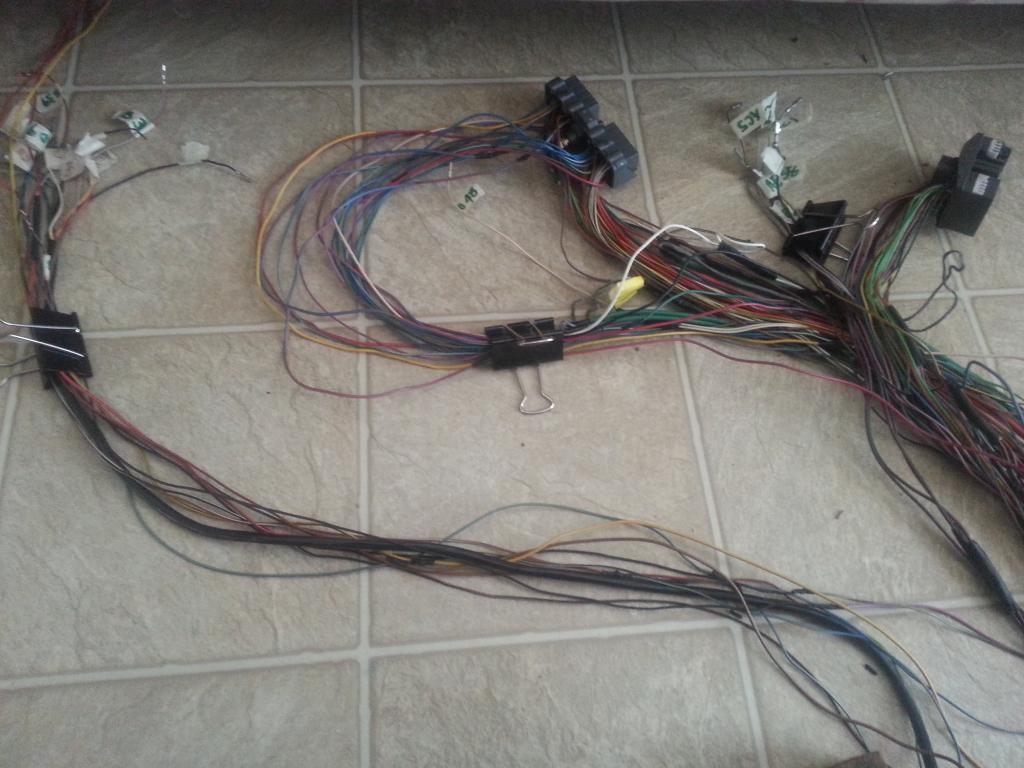
Are you still with me ? Ready to jump to another part of the harness ?
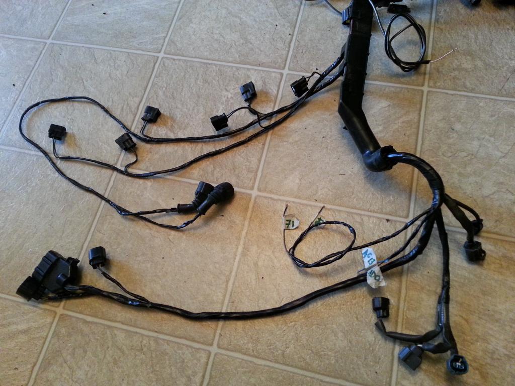
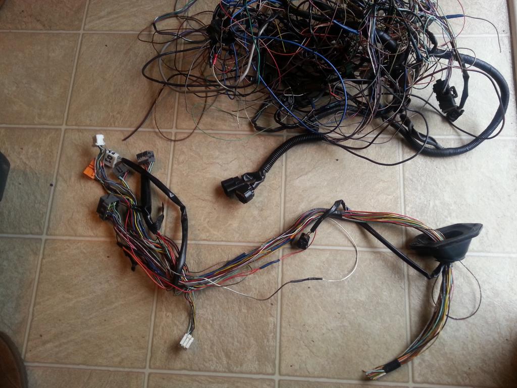
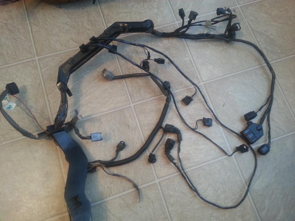
I am referring to these ones pictured here . They are next in line .
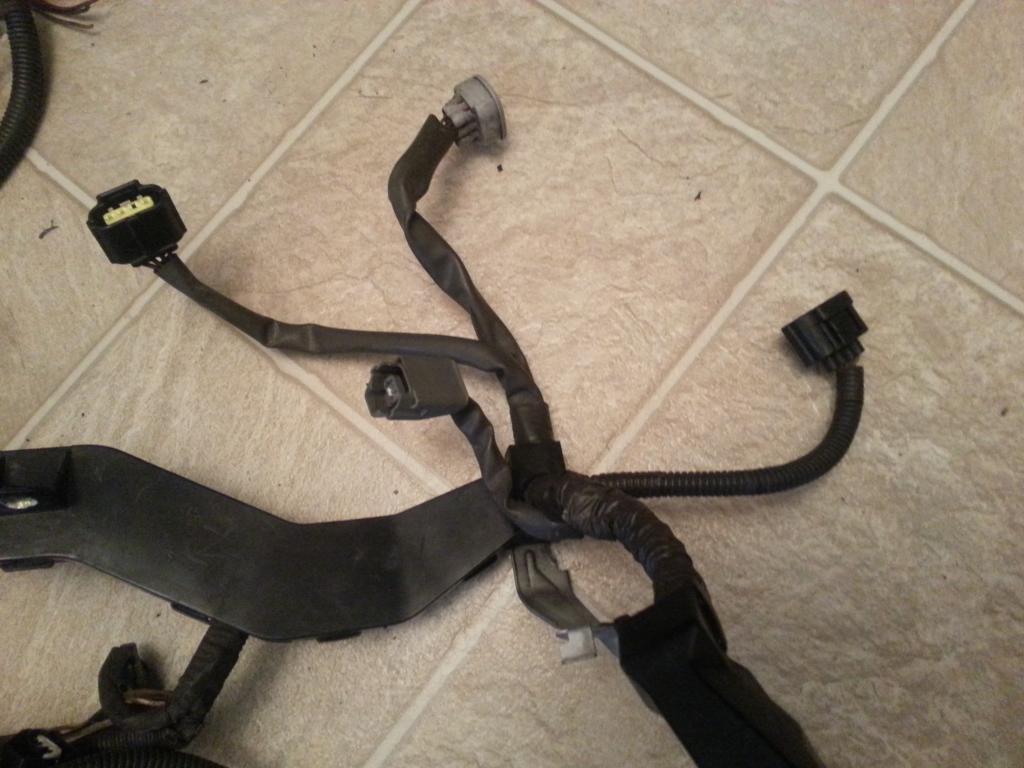
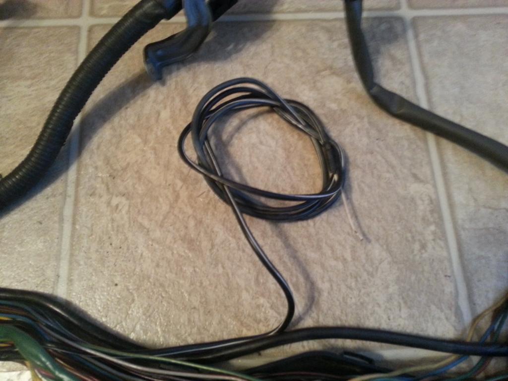
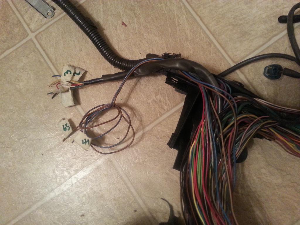
For the Red Mamba 2 harness, I have unwrapped up to a certain point so I can pull out the O2 sensor Pin 3 wire out as you see on the bottom left of the picture
Let's label the connectors and let me give you the INFO you need to do THE DRILL
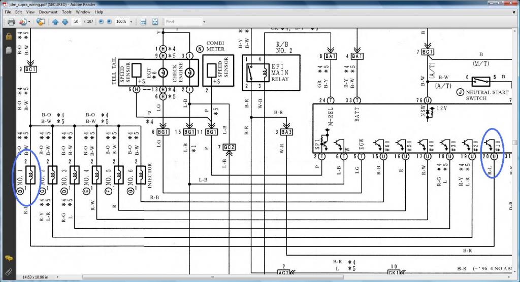
1) Injector No. 1
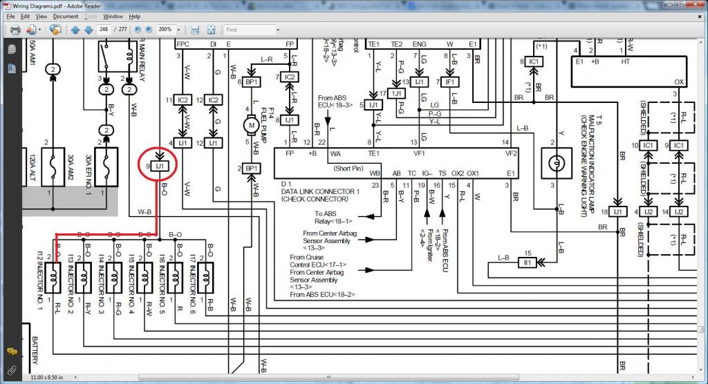
Pin 1 of Injector No. 1 goes to Pin 20 of the 80 pin ECU Connector
Pin 2 of Injector No. 1 (should go to (SC3 IJ1-7 or IJ1-3 & short 3 & short 5 , SC40 EB2-2 , MK4 IJ1-9))
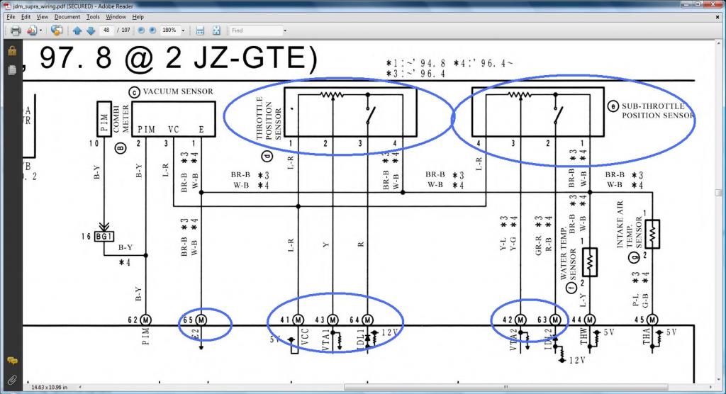
2) Sub-Throttle Position Sensor
Pin 1 of Sub-Throttle Position Sensor goes also to Pin 65 of the 80 pin ECU Connector
Pin 2 of Sub-Throttle Position Sensor goes to Pin 63 of the 80 pin ECU Connector
Pin 3 of Sub-Throttle Position Sensor goes to Pin 42 of the 80 pin ECU Connector
Pin 4 of Sub-Throttle Position Sensor goes also to Pin 41 of the 80 pin ECU Connector
3) Throttle Motor Valve
Pin 1 of Throttle Motor Valve goes to Pin 8 of Plug C of Big Gray Aristo Plug
Pin 2 of Throttle Motor Valve goes to Pin 11 of Plug C of Big Gray Aristo Plug
Pin 3 of Throttle Motor Valve goes to Pin 7 of Plug C of Big Gray Aristo Plug
Pin 4 of Throttle Motor Valve goes to Pin 4 of Plug C of Big Gray Aristo Plug
Pin 5 of Throttle Motor Valve goes to Pin 6 of Plug C of Big Gray Aristo Plug
Pin 6 of Throttle Motor Valve goes to Pin 3 of Plug C of Big Gray Aristo Plug
4) Throttle Position Sensor
Pin 1 of Throttle Position Sensor goes to Pin 41 of the 80 pin ECU Connector
Pin 2 of Throttle Position Sensor goes to Pin 43 of the 80 pin ECU Connector
Pin 3 of Throttle Position Sensor goes to Pin 64 of the 80 pin ECU Connector
Pin 4 of Throttle Position Sensor goes to Pin 65 of the 80 pin ECU Connector
Guys , go and do THE DRILL
I am referring to these ones pictured here . They are next in line .

For the Red Mamba 2 harness, I have unwrapped up to a certain point so I can pull out the O2 sensor Pin 3 wire out as you see on the bottom left of the picture

Let's label the connectors and let me give you the INFO you need to do THE DRILL
1) Injector No. 1
Pin 1 of Injector No. 1 goes to Pin 20 of the 80 pin ECU Connector
Pin 2 of Injector No. 1 (should go to (SC3 IJ1-7 or IJ1-3 & short 3 & short 5 , SC40 EB2-2 , MK4 IJ1-9))
2) Sub-Throttle Position Sensor
Pin 1 of Sub-Throttle Position Sensor goes also to Pin 65 of the 80 pin ECU Connector
Pin 2 of Sub-Throttle Position Sensor goes to Pin 63 of the 80 pin ECU Connector
Pin 3 of Sub-Throttle Position Sensor goes to Pin 42 of the 80 pin ECU Connector
Pin 4 of Sub-Throttle Position Sensor goes also to Pin 41 of the 80 pin ECU Connector
3) Throttle Motor Valve
Pin 1 of Throttle Motor Valve goes to Pin 8 of Plug C of Big Gray Aristo Plug
Pin 2 of Throttle Motor Valve goes to Pin 11 of Plug C of Big Gray Aristo Plug
Pin 3 of Throttle Motor Valve goes to Pin 7 of Plug C of Big Gray Aristo Plug
Pin 4 of Throttle Motor Valve goes to Pin 4 of Plug C of Big Gray Aristo Plug
Pin 5 of Throttle Motor Valve goes to Pin 6 of Plug C of Big Gray Aristo Plug
Pin 6 of Throttle Motor Valve goes to Pin 3 of Plug C of Big Gray Aristo Plug
4) Throttle Position Sensor
Pin 1 of Throttle Position Sensor goes to Pin 41 of the 80 pin ECU Connector
Pin 2 of Throttle Position Sensor goes to Pin 43 of the 80 pin ECU Connector
Pin 3 of Throttle Position Sensor goes to Pin 64 of the 80 pin ECU Connector
Pin 4 of Throttle Position Sensor goes to Pin 65 of the 80 pin ECU Connector
Guys , go and do THE DRILL
Last edited by gerrb; 01-31-14 at 03:37 PM.
01-31-14, 03:36 PM
#37
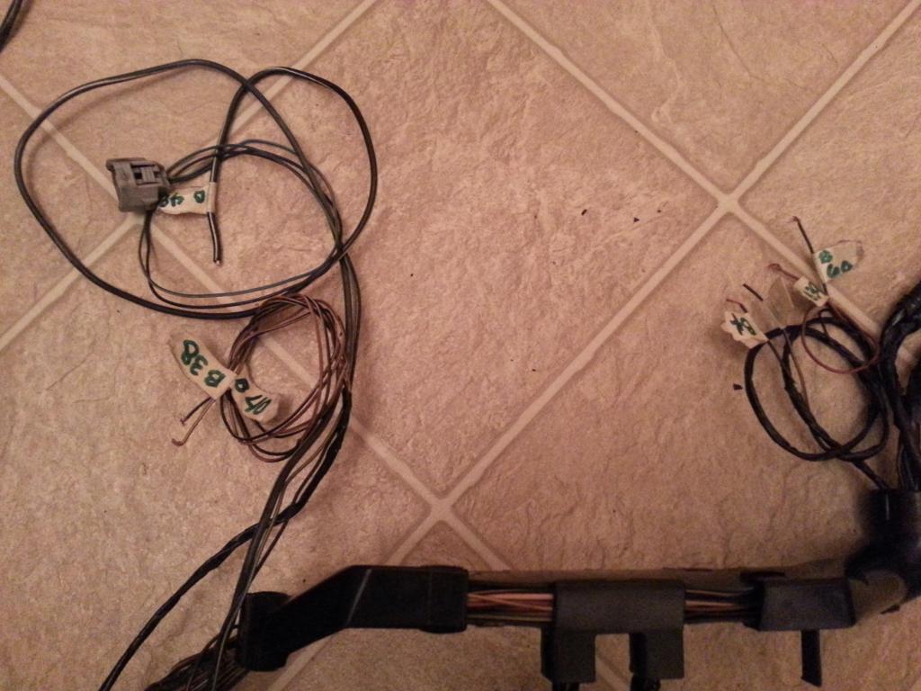
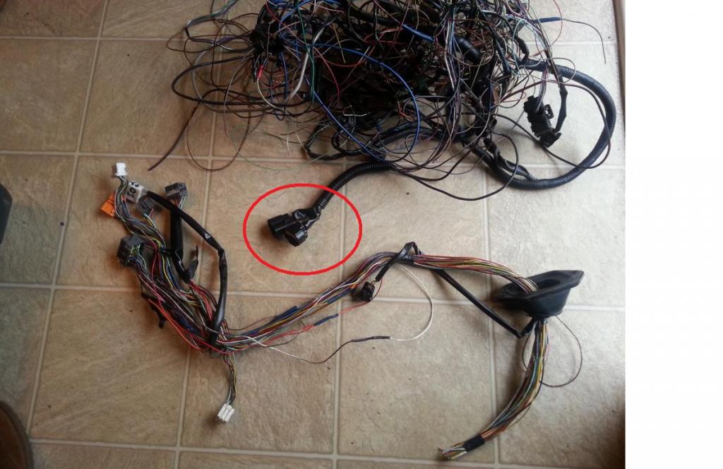
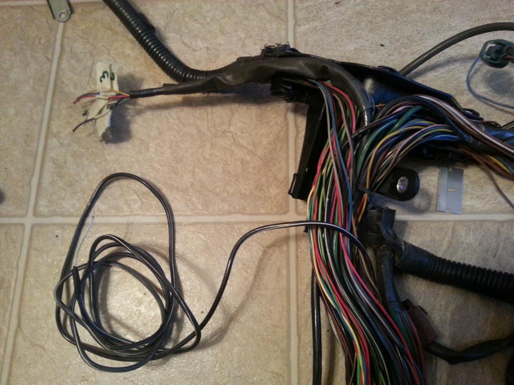
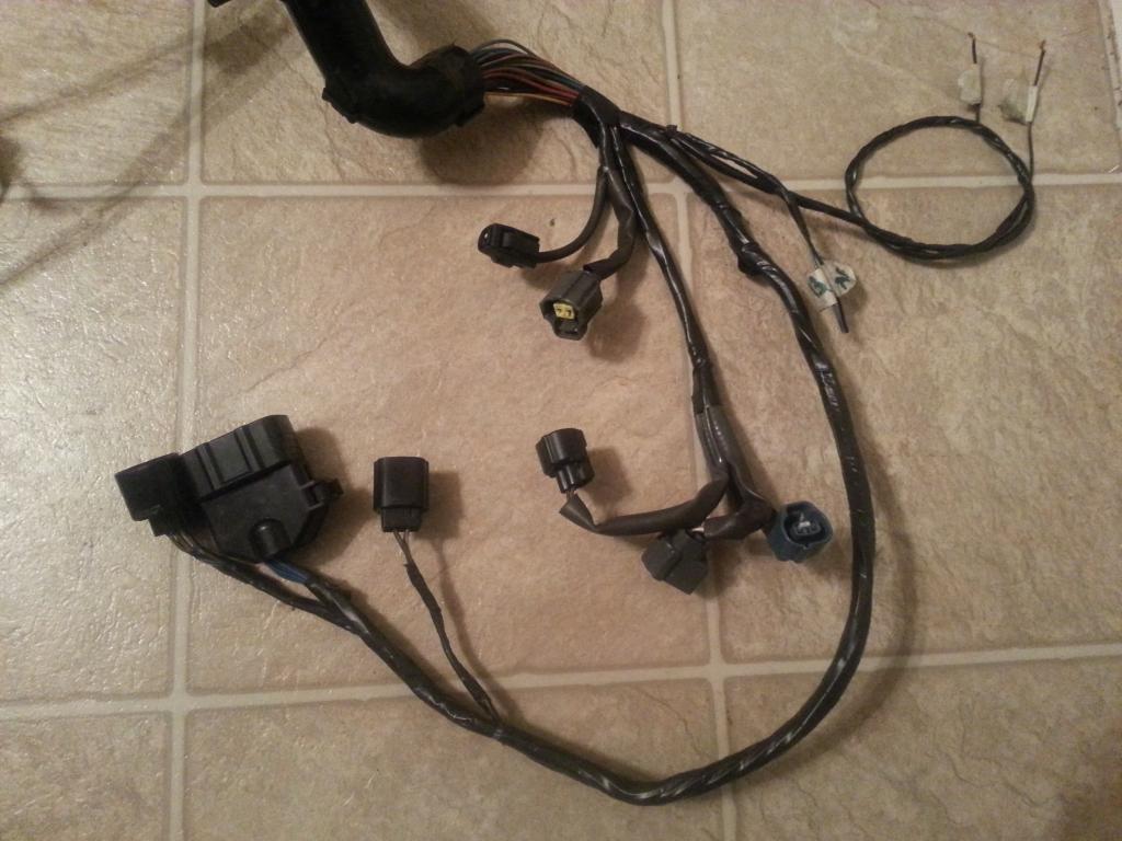
For Aaron's harness , the sub-throttle position sensor plug was already missing on the 2jzgte Aristo harness.
Pulled the wires to be taken out as far as I can , moved those two wires which I will use for my Air Intake Temp sensor and wrapped some part of that harness just to make it clean and prevent those wires from being unruly.
On the second harness I am working on , started with this at this point
I usually take out those throttle motor valve and sub-throttle position sensor plugs . Even if I have to use a Q45 throttle body with a tps that moves in the opposite direction , I can just move around the pins of the original TPS. So these two plugs (throttle motor valve and sub-throttle position sensor are excellent donors for extra wiring for whatever aftermarket sensor you need to wire.
Basically most sensors will need a +voltage and sensor ground. You can get them from Pin 1 (Sensor Ground) and Pin 4 (+Voltage) of the sub-throttle position sensor.
All your aftermarket sensors can have their +Voltage and sensor ground T'ed from the same place like this Pin 1 and Pin 4 of the sub-throttle position sensor
Now listen here carefully if you want to follow what I did on these extra wires .
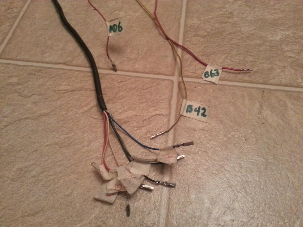
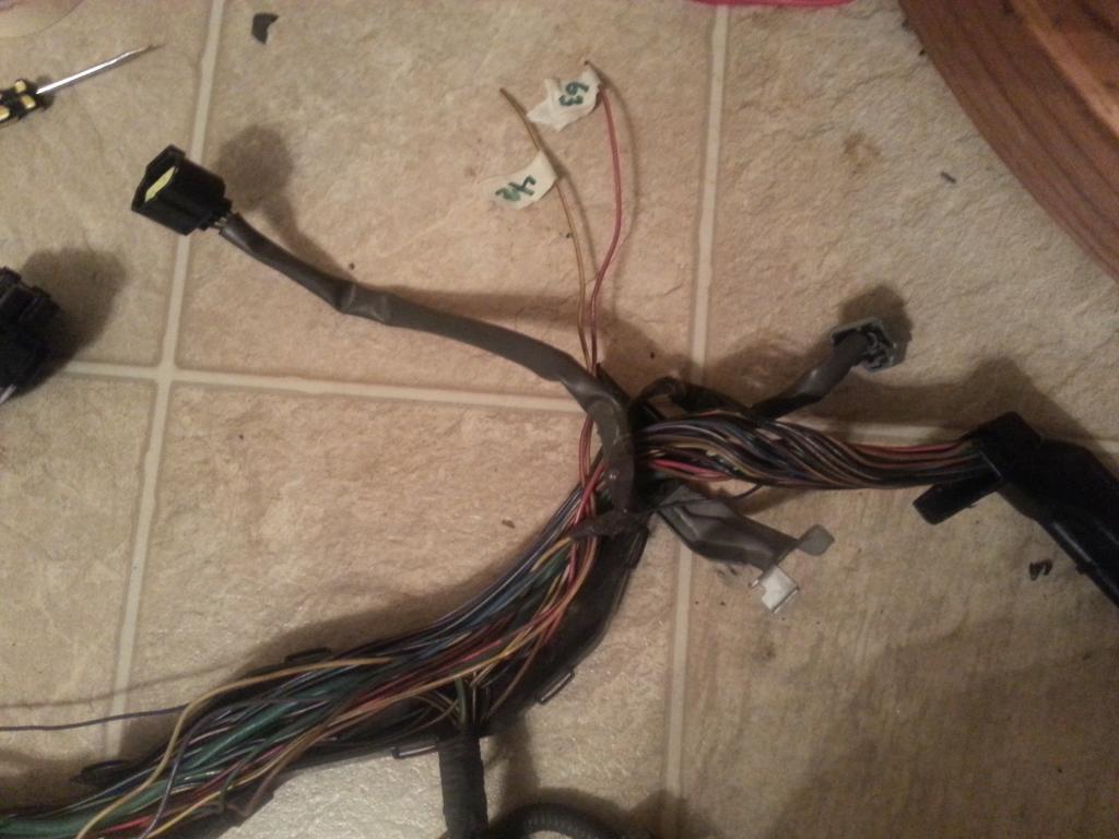
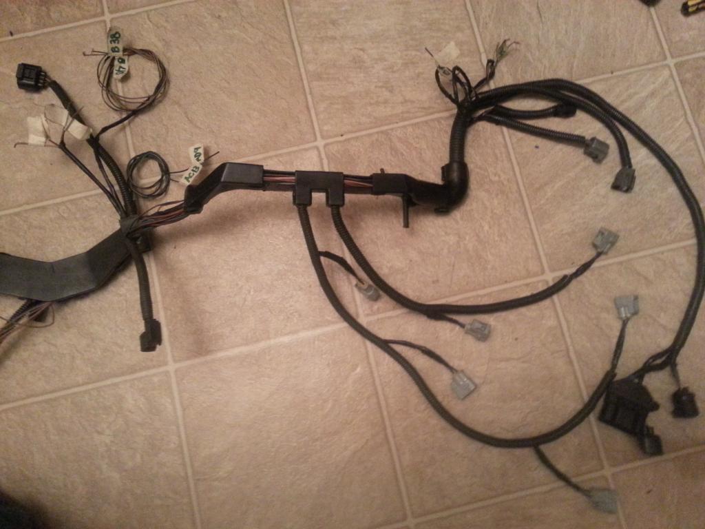
As mentioned above Pin 3 of the Sub-TPS goes to Pin 42 of the 80 pin ECU Connector and Pin 2 of the Sub-TPS goes to Pin 63 of the 80 pin ECU Connector. I took them out of their 80 pin ECU connector . NOTE : pin 63 of the 80 pin ECU Connector is T'ed to a wire that goes to Pin 6 of Plug D of the Aristo Plug. It's for the traction control open switch which you don't need .Take that out too . But take a note of this one (You many need this info on your SC300 / SC400 / MKIV harness. This maybe in your harness going to a body plug which eventually can probably be taken out) . But for now put labels. Then I took out all the 6 wires with the shield wire from the Plug C of the Aristo plug and labeled them as you see below . Damn , I am a sucker of extra wires on the harness ..lmaol ... hey trust me they will come very handy when you have a lot of after market sensors.
I extended the wires from Pin 42 and Pin 63 of the 80 pin ECU Connector but I didn't extend the 6 wires from the Throttle Motor Valve. I will tell you why in a bit.
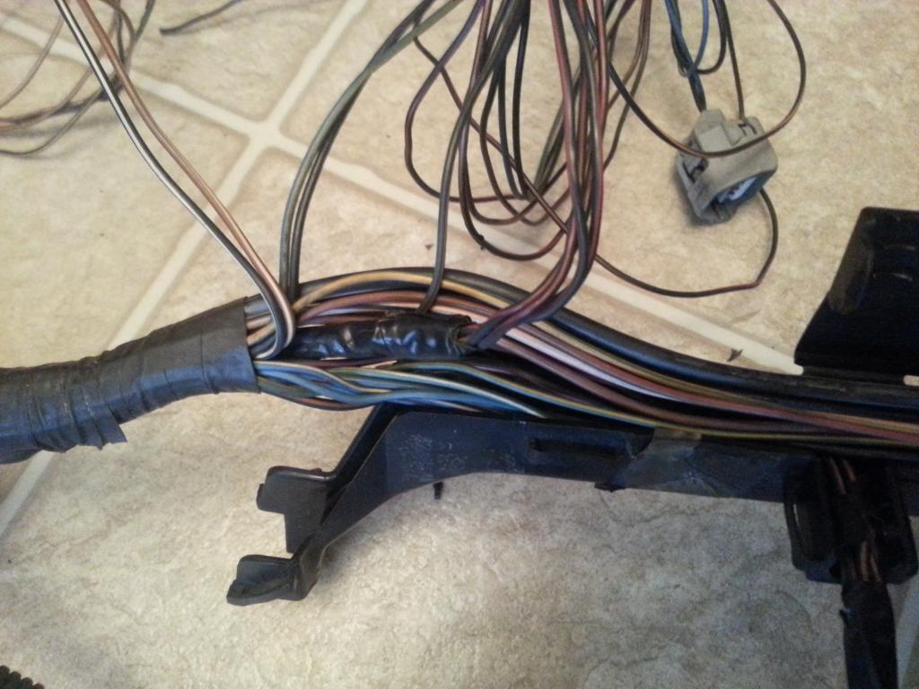
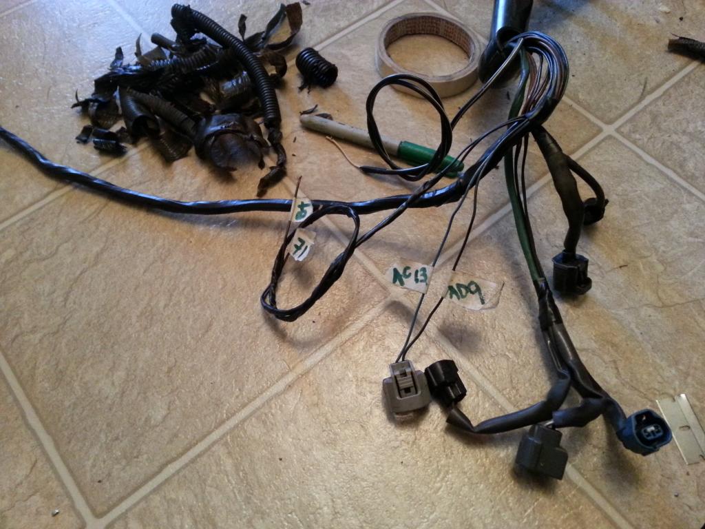
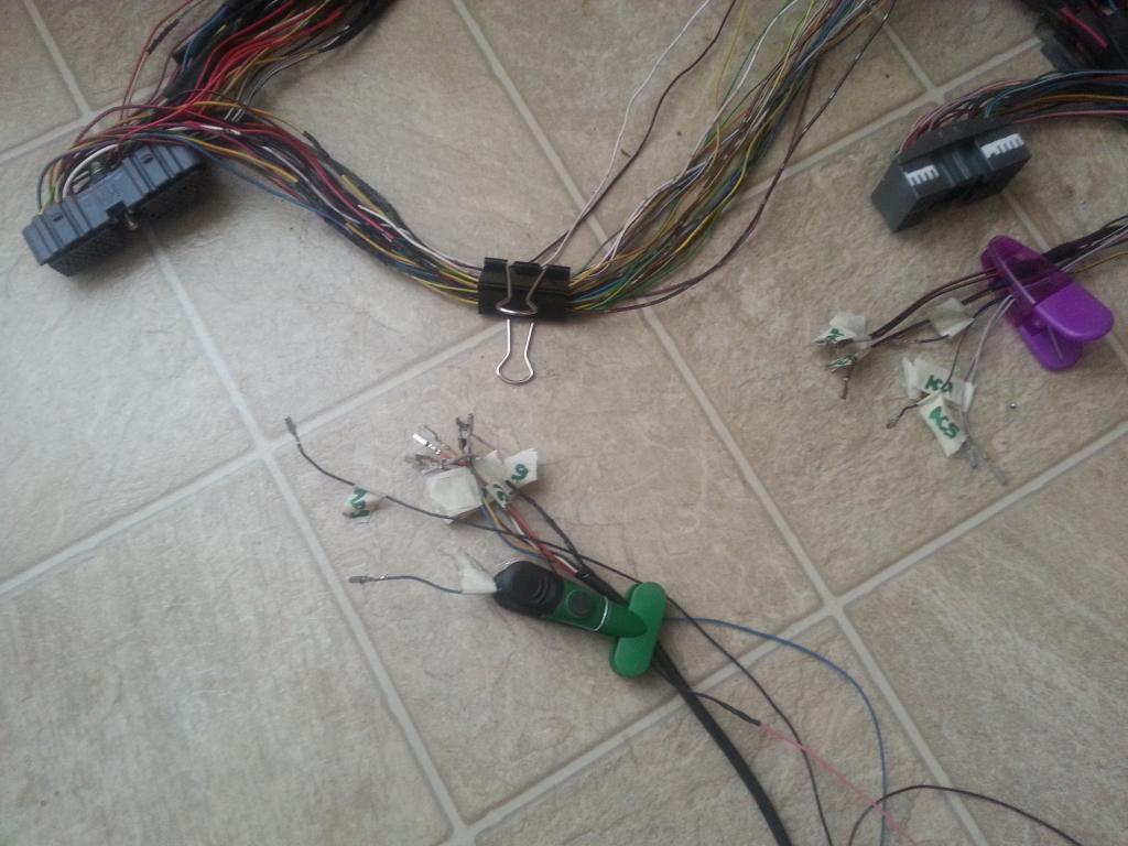
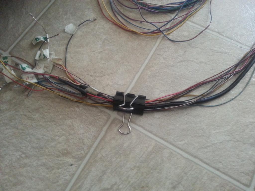
At this point , I have to take out all the remaining wraps and covers on the harness. Be careful , don't let the wires be all over the place and be messy.
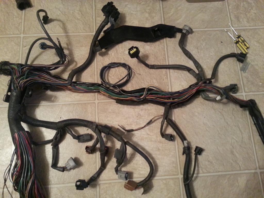
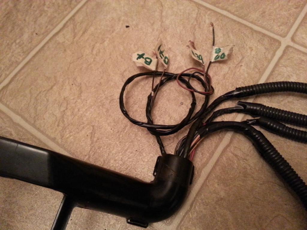
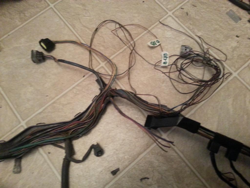
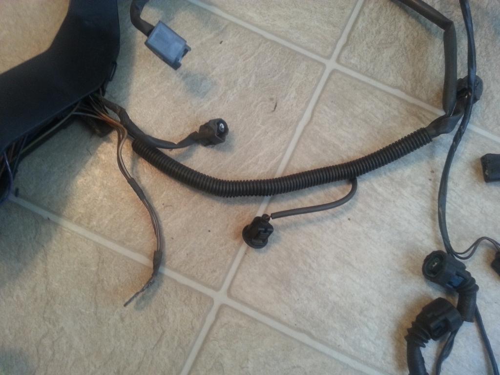
I wanted to pull those bunch of wires (6 wires from Throttle Valve Motor) which I already labeled and whose plug I already cut and the Oxygen Sensor wire out of that place .

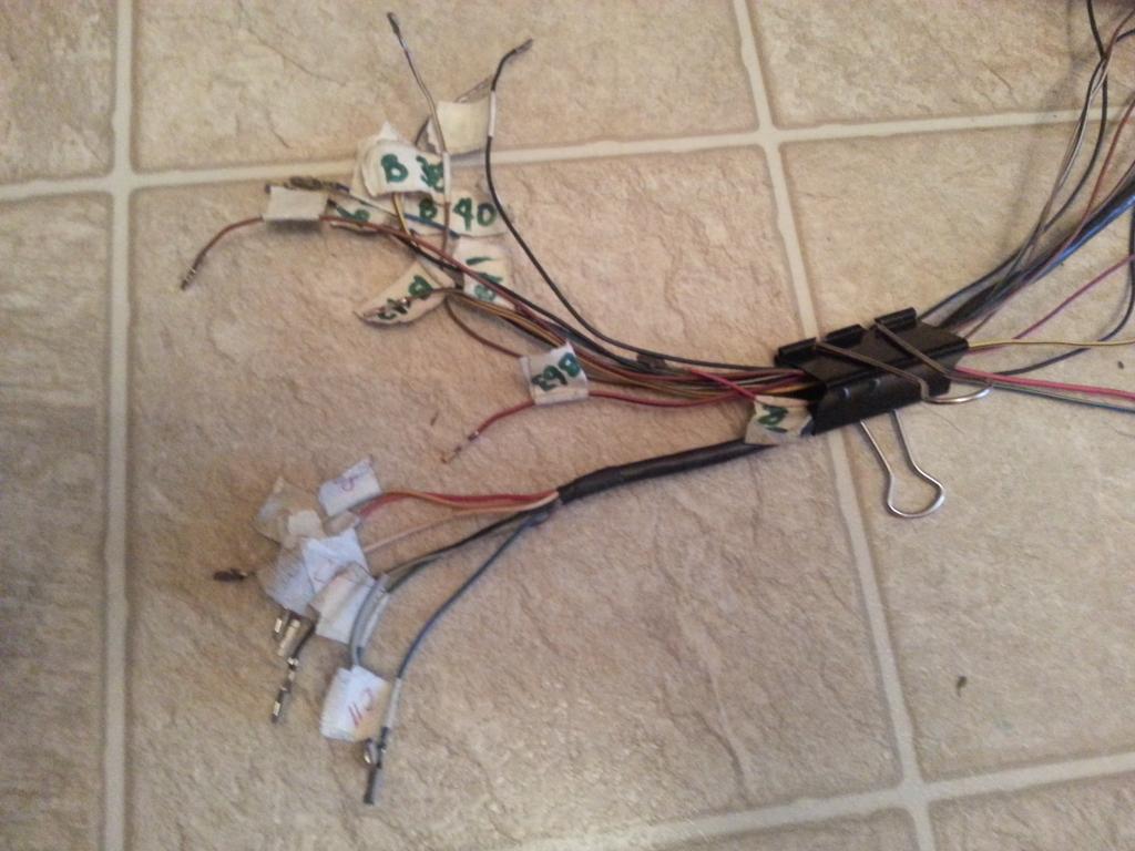
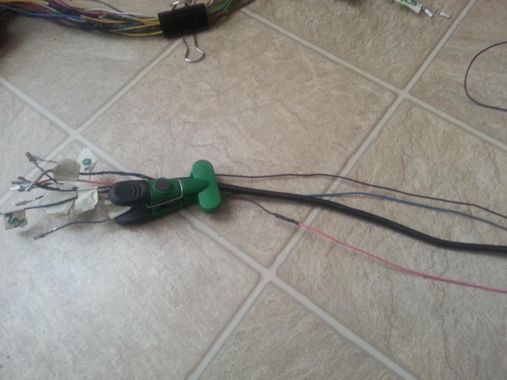
close up of 6 wires
close up of oxygen sensor wire
moved them here
I don't need all those extra wires for now so I will leave them here and when I need some , I know where they are . So why did I not extend those 6 wires from the throttle Motor Valve ? By moving them from front to the back part (firewall area) , you can pull their other end now so they would be of the same length as your other extended extra wires. Here you see all my extra wires all clipped together but well labeled so I know which is which.
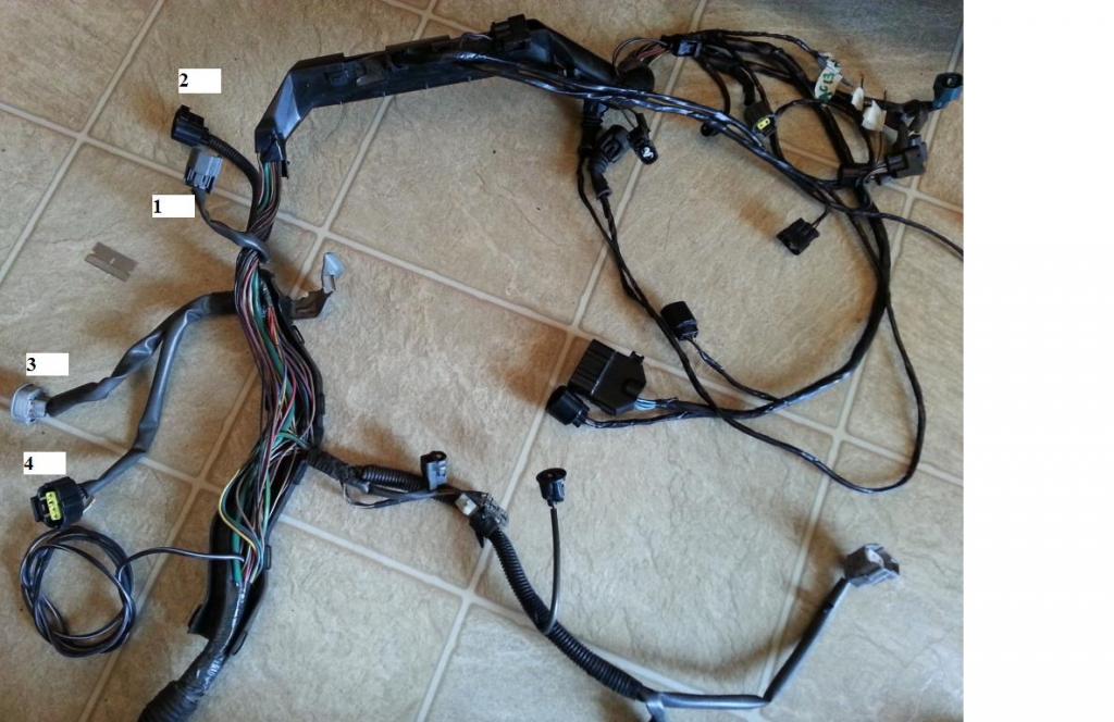
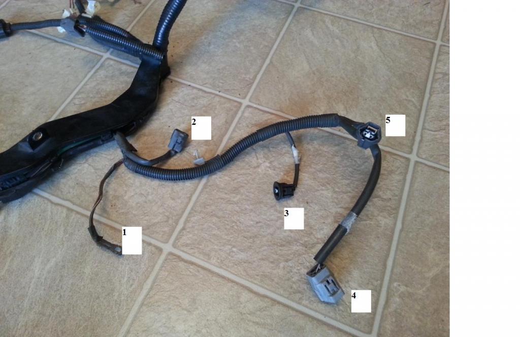
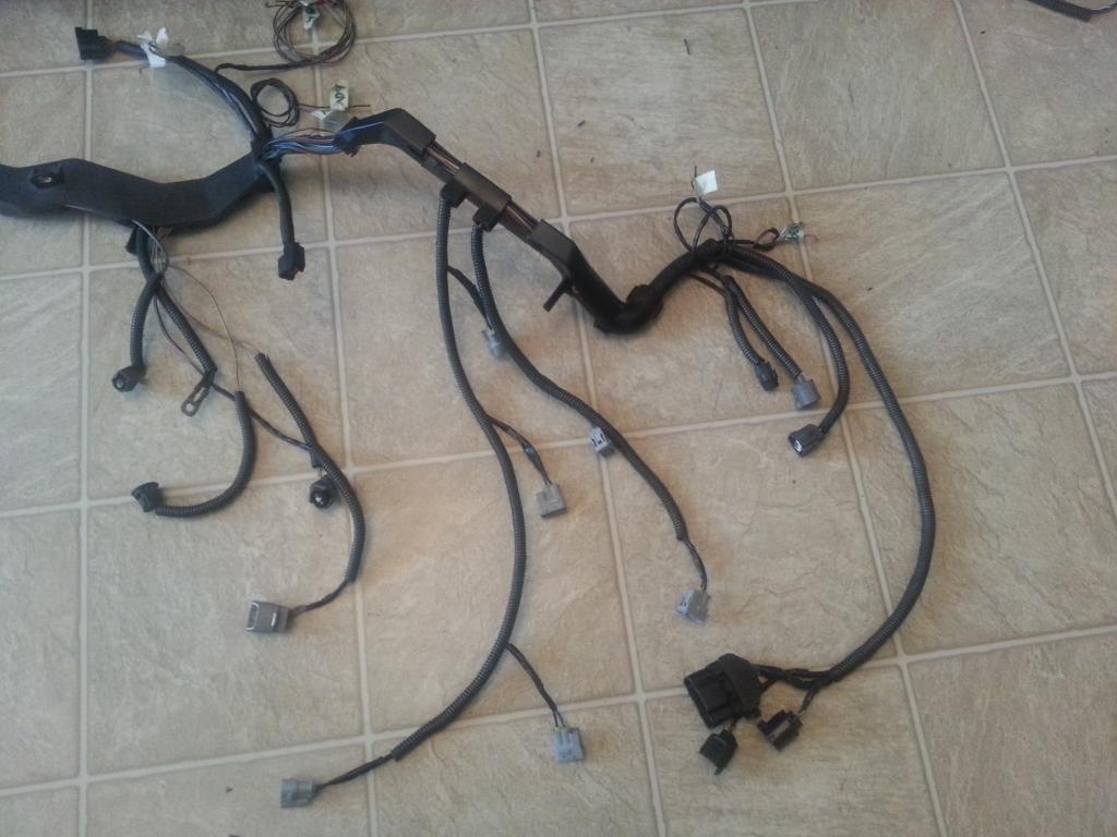
Let me show you how the ECU connectors end of the harness for Aaron. On the left are all the extra wires . Then you have the 80 pin ECU connector which by just looking at it , you have an idea how many have been extended already and how much more wires to work on. Then you have those wires I took out of the Aristo plug that need to be extended and needs to go to the body plugs and next the Aristo plug itself.
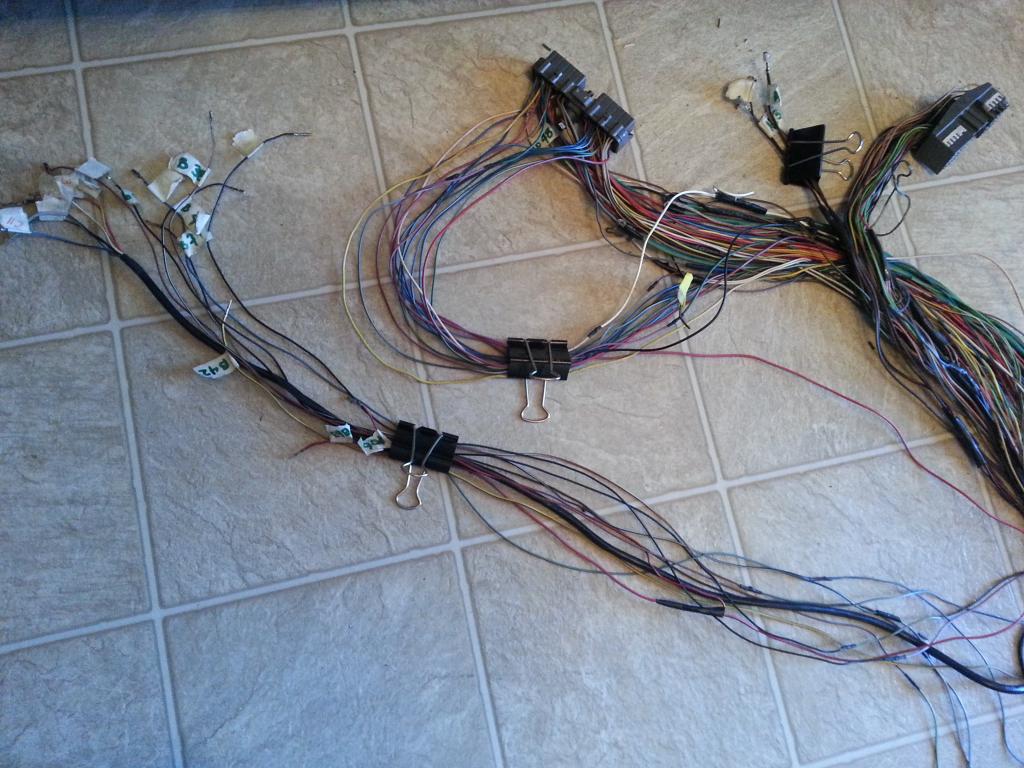
And this is Aaron's harness where the TPS connector andinjector #1 is. I have 6 individual extra wires plus the +Voltage ( from pin 41) and ground (from pin 65) on that area which can be used for different sensors . Remember that pin 41 and pin 65 wire can be used as voltage supply for all those sensors.
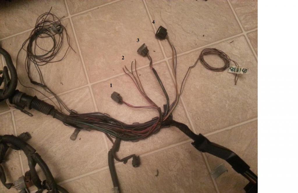
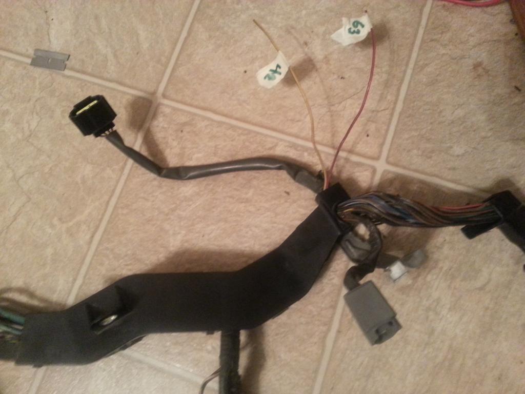
For my second SC harness which is the Red Mamba 2 , this is what I did. You know that I already moved the 6 throttle motor valve wires near the firewall as extra wires but they will need +Voltage and Ground supplies if I will use those wires for sensors . So what did I do . I moved Pin 1 of Sub-TPS (goes to pin 65 of 80 pin ECU Connector) and Pin 4 of Sub-TPS (goes to pin 41 of 80 pin ECU Connector) to the back near the firewall . What is left of the Sub-TPS plug in front was Pin 2 and Pin 3 of the Sub-TPS as extra wires eventually for my Air Temp Sensor .
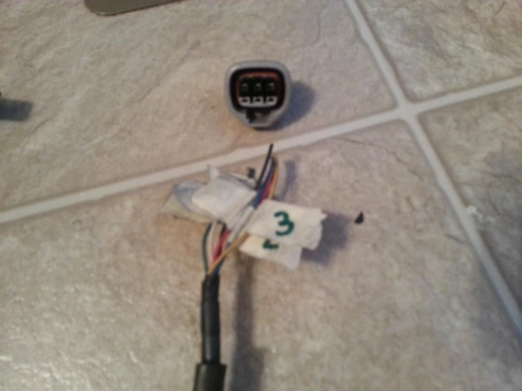
Here you see the wires of the sub-tps with label and am about to cut that plug

On this picture I have moved Pin 1 and Pin 4 of sub-tps to the back near those 6 extra wires for future sensors.
So what is left in front is the TPS and Injector #1 plug plus 2 individual extra wires .

Pulled the wires to be taken out as far as I can , moved those two wires which I will use for my Air Intake Temp sensor and wrapped some part of that harness just to make it clean and prevent those wires from being unruly.

On the second harness I am working on , started with this at this point

I usually take out those throttle motor valve and sub-throttle position sensor plugs . Even if I have to use a Q45 throttle body with a tps that moves in the opposite direction , I can just move around the pins of the original TPS. So these two plugs (throttle motor valve and sub-throttle position sensor are excellent donors for extra wiring for whatever aftermarket sensor you need to wire.
Basically most sensors will need a +voltage and sensor ground. You can get them from Pin 1 (Sensor Ground) and Pin 4 (+Voltage) of the sub-throttle position sensor.
All your aftermarket sensors can have their +Voltage and sensor ground T'ed from the same place like this Pin 1 and Pin 4 of the sub-throttle position sensor
Now listen here carefully if you want to follow what I did on these extra wires .
As mentioned above Pin 3 of the Sub-TPS goes to Pin 42 of the 80 pin ECU Connector and Pin 2 of the Sub-TPS goes to Pin 63 of the 80 pin ECU Connector. I took them out of their 80 pin ECU connector . NOTE : pin 63 of the 80 pin ECU Connector is T'ed to a wire that goes to Pin 6 of Plug D of the Aristo Plug. It's for the traction control open switch which you don't need .Take that out too . But take a note of this one (You many need this info on your SC300 / SC400 / MKIV harness. This maybe in your harness going to a body plug which eventually can probably be taken out) . But for now put labels. Then I took out all the 6 wires with the shield wire from the Plug C of the Aristo plug and labeled them as you see below . Damn , I am a sucker of extra wires on the harness ..lmaol ... hey trust me they will come very handy when you have a lot of after market sensors.
I extended the wires from Pin 42 and Pin 63 of the 80 pin ECU Connector but I didn't extend the 6 wires from the Throttle Motor Valve. I will tell you why in a bit.

At this point , I have to take out all the remaining wraps and covers on the harness. Be careful , don't let the wires be all over the place and be messy.

I wanted to pull those bunch of wires (6 wires from Throttle Valve Motor) which I already labeled and whose plug I already cut and the Oxygen Sensor wire out of that place .

close up of 6 wires

close up of oxygen sensor wire

moved them here

I don't need all those extra wires for now so I will leave them here and when I need some , I know where they are . So why did I not extend those 6 wires from the throttle Motor Valve ? By moving them from front to the back part (firewall area) , you can pull their other end now so they would be of the same length as your other extended extra wires. Here you see all my extra wires all clipped together but well labeled so I know which is which.

Let me show you how the ECU connectors end of the harness for Aaron. On the left are all the extra wires . Then you have the 80 pin ECU connector which by just looking at it , you have an idea how many have been extended already and how much more wires to work on. Then you have those wires I took out of the Aristo plug that need to be extended and needs to go to the body plugs and next the Aristo plug itself.

And this is Aaron's harness where the TPS connector andinjector #1 is. I have 6 individual extra wires plus the +Voltage ( from pin 41) and ground (from pin 65) on that area which can be used for different sensors . Remember that pin 41 and pin 65 wire can be used as voltage supply for all those sensors.

For my second SC harness which is the Red Mamba 2 , this is what I did. You know that I already moved the 6 throttle motor valve wires near the firewall as extra wires but they will need +Voltage and Ground supplies if I will use those wires for sensors . So what did I do . I moved Pin 1 of Sub-TPS (goes to pin 65 of 80 pin ECU Connector) and Pin 4 of Sub-TPS (goes to pin 41 of 80 pin ECU Connector) to the back near the firewall . What is left of the Sub-TPS plug in front was Pin 2 and Pin 3 of the Sub-TPS as extra wires eventually for my Air Temp Sensor .
Here you see the wires of the sub-tps with label and am about to cut that plug

On this picture I have moved Pin 1 and Pin 4 of sub-tps to the back near those 6 extra wires for future sensors.

So what is left in front is the TPS and Injector #1 plug plus 2 individual extra wires .


Last edited by gerrb; 01-31-14 at 04:02 PM.
01-31-14, 03:37 PM
#38
Let us update our CHART
80 PIN ECU CONNECTOR
1
2
7 <--> Pin 2 of the Crankshaft Position Sensor CHECKED
10
20 <--> Pin 1 of the Injector No. 1 CHECKED
27 <--> Pin 1 of the Crankshaft Position Sensor CHECKED
30
38 <--> Pin 2 of the VSV3 CHECKED
39 <--> Pin 2 of the VSV2 CHECKED
40 <--> Pin 2 of the VSV1 CHECKED
41 <--> Pin 1 of the TPS <--> Pin 4 of the Sub-TPS CHECKED
42 <--> Pin 3 of the Sub-TPS CHECKED
43 <--> Pin 2 of the TPS CHECKED
44 <--> Pin 2 of the Water Temperature Sensor CHECKED
48 <--> Pin 3 of the O2 Sensor CHECKED
50
51
52 <--> Pin 7 of the 12 pin Igniter Connector CHECKED
53 <--> Pin 8 of the 12 pin igniter Connector CHECKED
54 <--> Pin 9 of the 12 pin igniter Connector CHECKED
55 <--> Pin 3 of the 12 pin igniter Connector CHECKED
56 <--> Pin 2 of the 12 pin Igniter Connector CHECKED
57 <--> Pin 1 of the 12 pin Igniter Connector CHECKED
58 <--> Pin 3 of the 4 pin Igniter Connector CHECKED
59
60 <--> Pin 2 of the VSVPMC CHECKED
63 <--> Pin 2 of the Sub-TPS CHECKED
64 <--> Pin 3 of the TPS CHECKED
65 <--> Pin 1 of the Water Temperature Sensor <--> Pin 4 of the TPS <--> Pin1 of the Sub-TPS CHECKED
70
71 <--> Pin 1 of the O2 Sensor CHECKED
80
4 PIN IGNITER CONNECTOR
1 <--> Pin 12 of Plug F of Aristo plug <--> ( Pin 19 of the Data Link Connector <--> ( SC3 IK1-8 , SC4 IK1-8 , MK4 ))
2 <--> Pin 6 of Plug F of Aristo plug <--> Pin 1 of the Noise Filter <--> ( SC3 IJ1-7 , SC4 EB2-2 , MK4 IJ1-1 or IJ1-9 )
3 <--> Pin 58 of the 80 pin ECU connector CHECKED
4 <--> Ground Connector on the Front Side of Intake Manifold <--> Pin 2 of the Noise filter Connector CHECKED
12 PIN IGNITER CONNECTOR
1 <--> Pin 57 of the 80 pin ECU connector CHECKED
2 <--> Pin 56 of the 80 pin ECU connector CHECKED
3 <--> Pin 55 of the 80 pin ECU connector CHECKED
4 <--> Pin 2 of the Ignition Coil Connector 3 CHECKED
5 <--> Pin 2 of the Ignition Coil Connector 2 CHECKED
6 <--> Pin 2 of the Ignition Coil Connector 1 CHECKED
7 <--> Pin 52 of the 80 pin ECU connector CHECKED
8 <--> Pin 53 of the 80 pin ECU connector CHECKED
9 <--> Pin 54 of the 80 pin ECU connector CHECKED
10 <--> Pin 2 of the Ignition Coil Connector 4 CHECKED
11 <--> Pin 2 of the Ignition Coil Connector 5 CHECKED
12 <--> Pin 2 of the Ignition Coil Connector 6 CHECKED
CRANKSHAFT POSITION SENSOR
1 <--> Pin 27 of the 80 pin ECU Connector CHECKED
2 <--> Pin 7 of the 80 pin ECU Connector CHECKED
IGNITION COIL 1
1 <--> Pin 1 of the Noise Filter <--> Pin 2 of the 4 pin Igniter Connector <--> Pin 1 of Ignition Coil 2,3,4,5,6 <-->( SC3 IJ1-7 , SC4 EB2-2 , MK4 IJ1-1 or IJ1-9 )
2 <--> Pin 6 of the 12 Pin Igniter Connector CHECKED
IGNITION COIL 2
1 <--> Pin 1 of the Noise Filter <--> Pin 2 of the 4 pin Igniter Connector <--> Pin 1 of Ignition Coil 1,3,4,5,6 <-->( SC3 IJ1-7 , SC4 EB2-2 , MK4 IJ1-1 or IJ1-9 )
2 <--> Pin 5 of the 12 Pin Igniter Connector CHECKED
IGNITION COIL 3
1 <--> Pin 1 of the Noise Filter <--> Pin 2 of the 4 pin Igniter Connector <--> Pin 1 of Ignition Coil 1,2,4,5,6 <-->( SC3 IJ1-7 , SC4 EB2-2 , MK4 IJ1-1 or IJ1-9 )
2 <--> Pin 4 of the 12 Pin Igniter Connector CHECKED
IGNITION COIL 4
1 <--> Pin 1 of the Noise Filter <--> Pin 2 of the 4 pin Igniter Connector <--> Pin 1 of Ignition Coil 1,2,3,5,6 <-->( SC3 IJ1-7 , SC4 EB2-2 , MK4 IJ1-1 or IJ1-9 )
2 <--> Pin 10 of the 12 Pin Igniter Connector CHECKED
IGNITION COIL 5
1 <--> Pin 1 of the Noise Filter <--> Pin 2 of the 4 pin Igniter Connector <--> Pin 1 of Ignition Coil 1,2,3,4,6 <-->( SC3 IJ1-7 , SC4 EB2-2 , MK4 IJ1-1 or IJ1-9 )
2 <--> Pin 11 of the 12 Pin Igniter Connector CHECKED
IGNITION COIL 6
1 <--> Pin 1 of the Noise Filter <--> Pin 2 of the 4 pin Igniter Connector <--> Pin 1 of Ignition Coil 1,2,3,4,5 <-->( SC3 IJ1-7 , SC4 EB2-2 , MK4 IJ1-1 or IJ1-9 )
2 <--> Pin 12 of the 12 Pin Igniter Connector CHECKED
INJECTOR NO. 1
1 <--> Pin 20 of the 80 pin ECU Connector
2 <--> (should go to (SC3 IJ1-7 or IJ1-3 & short 3 & short 5 , SC40 EB2-2 , MK4 IJ1-9))
NOISE FILTER
1 <--> Pin 2 of the 4 pin Igniter Connector <--> ( SC3 IJ1-7, SC4 EB2-2 , MK4 IJ1-1 or IJ1-9 )
2 <--> Ground Connector on the Front Side of Intake Manifold <--> Pin 4 of the 4 pin Igniter Connector CHECKED
Throttle Position Sensor
1 <--> Pin 41 of the 80 pin ECU Connector
2 <--> Pin 43 of the 80 pin ECU Connector
3 <--> Pin 64 of the 80 pin ECU Connector
4 <--> Pin 65 of the 80 pin ECU Connector
WATER TEMPERATURE SENSOR
1 <--> Pin 65 of the 80 pin ECU Connector CHECKED
2 <--> Pin 44 of the 80 pin ECU Connector CHECKED
WATER TEMPERATURE GAUGE SENDER
1 <--> Pin 9 of Plug F of the Big Gray Aristo Plug (should go to SC3 IK1-9 , SC4 IK1-9 & Short-3 , MK4 II1-19 )
The following plugs are necessary only if you are going stock 2jzgte setup
OXYGEN SENSOR (O2)
1 <--> Pin 71 of the 80 pin ECU Connector CHECKED
2 <--> Pin 3 of Plug E of Aristo Plug <-> (Pin 12 of the Data Link Connector <--> ( SC3 IJ1-12 & EB2-1 & Short-4 , SC4 IJ1-12 & EB2-3 , MK4 EA3-3 ))
3 <--> Pin 48 of the 80 pin ECU Connector CHECKED
VSV1 ( Air Intake Control Valve )
1 <--> Pin 2 of the O2 Sensor <--> Pin 1 of the VSV3 <-> (Pin 12 of the Data Link Connector <--> ( SC3 IJ1-12 & EB2-1 & Short-4 , SC4 IJ1-12 & EB2-3 , MK4 EA3-3 ))
2 <--> Pin 40 of the 80 pin ECU Connector CHECKED
VSV2 ( Exhaust Control Valve )
1 <--> Pin 1 of VSV1 , VSV3 , VSVPMC <--> Pin 2 of the O2 Sensor <--> Pin 1 of the VSV3 <-> (Pin 12 of the Data Link Connector <--> ( SC3 IJ1-12 & EB2-1 & Short-4 , SC4 IJ1-12 & EB2-3 , MK4 EA3-3 ))
2 <--> Pin 39 of the 80 pin ECU Connector CHECKED
VSV3( Exhaust Bypass Valve )
1 <--> Pin 2 of the O2 Sensor <-->Pin 1 of the VSV1 <-> (Pin 12 of the Data Link Connector <--> ( SC3 IJ1-12 & EB2-1 & Short-4 , SC4 IJ1-12 & EB2-3 , MK4 EA3-3 ))
2 <--> Pin 38 of the 80 pin ECU Connector CHECKED
VSVPMC ( Waste Gate Valve )
1 <--> Pin 1 of VSV1 , VSV2 , VSV3 <--> Pin 2 of the O2 Sensor <--> Pin 1 of the VSV3 <-> (Pin 12 of the Data Link Connector <--> ( SC3 IJ1-12 & EB2-1 & Short-4 , SC4 IJ1-12 & EB2-3 , MK4 EA3-3 ))
2 <--> Pin 60 of the 80 pin ECU Connector CHECKED
The following plugs maybe kept or deleted depending on your seup
2) Sub-Throttle Position Sensor
1 <--> Pin 65 of the 80 pin ECU Connector
2 <--> Pin 63 of the 80 pin ECU Connector
3 <--> Pin 42 of the 80 pin ECU Connector
4 <--> Pin 41 of the 80 pin ECU Connector
The following plugs are usually deleted
Throttle Motor Valve
1 <--> Pin 8 of Plug C of Big Gray Aristo Plug
2 <--> Pin 11 of Plug C of Big Gray Aristo Plug
3 <--> Pin 7 of Plug C of Big Gray Aristo Plug
4 <--> Pin 4 of Plug C of Big Gray Aristo Plug
5 <--> Pin 6 of Plug C of Big Gray Aristo Plug
6 <--> Pin 3 of Plug C of Big Gray Aristo Plug
The following plug definitely will be deleted but its wires go to different body plugs or 40 pin ECU Connector or can be used for future needs
BIG GRAY ARISTO PLUG
PLUG C
3 <--> Extra Wire for future use CHECKED
4 <--> Extra Wire for future use CHECKED
6 <--> Extra Wire for future use CHECKED
7 <--> Extra Wire for future use CHECKED
8 <--> Extra Wire for future use CHECKED
11 <--> Extra Wire for future use CHECKED
13 <--> Extra Wire for future use CHECKED
PLUG D
6 <--> Pin 63 of the 80 pin ECU Connector (Is still needed ????? remains to be seen during the merge process)
9 <--> Extra Wire for future use CHECKED
PLUG E
3 <--> Pin 2 of Oxygen Sensor <--> (Pin 12 of the Data Link Connector <--> ( SC3 IJ1-12 & EB2-1 & Short-4 , SC4 IJ1-12 & EB2-3 , MK4 EA3-3 ))
PLUG F
6 <--> Pin 1 of the Noise Filter <--> ( SC3 IJ1-7 , SC4 EB2-2 , MK4 IJ1-1 or IJ1-9 )
9 <--> Pin 1 of the Water Temperature Gauge Sender <--> ( SC3 IK1-9 , SC4 IK1-9 & Short-3 , MK4 II1-19 )
12 <--> ( Pin 19 of the Data Link Connector & to ( SC3 IK1-8 , SC4 IK1-8 , MK4 ))
Last edited by gerrb; 06-03-14 at 07:43 AM.
01-31-14, 04:01 PM
#39
DIAGRAMS TO VERIFY PIN NUMBERING & WHERE THE WIRE GOES
*** Throttle and Sub-Throttle Position Sensors ***
Injector No. 1
DIAGRAMS TO VERIFY WHERE A WIRE SHOULD GO IN A SC300, SC400, MKIV
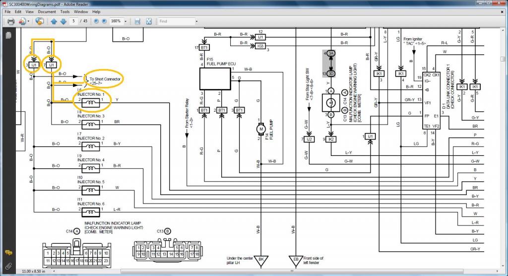
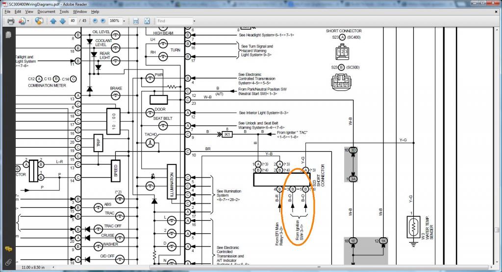
How do we know that Pin 2 of the Injectors should go to (SC3 IJ1-7 or IJ1-3 & short 3 & short 5 , SC40 EB2-2 , MK4 IJ1-9))
SC300
following the link above for the short connector
SC400 This SC400 diagram shows me that the injectors gets their B+ supply from the Ignition Main Relay
following the link , it leads me to EB2 pin 2
MKIV
*** Throttle and Sub-Throttle Position Sensors ***

Injector No. 1

DIAGRAMS TO VERIFY WHERE A WIRE SHOULD GO IN A SC300, SC400, MKIV
How do we know that Pin 2 of the Injectors should go to (SC3 IJ1-7 or IJ1-3 & short 3 & short 5 , SC40 EB2-2 , MK4 IJ1-9))
SC300

following the link above for the short connector

SC400 This SC400 diagram shows me that the injectors gets their B+ supply from the Ignition Main Relay

following the link , it leads me to EB2 pin 2

MKIV

Last edited by gerrb; 01-31-14 at 04:26 PM.
01-31-14, 04:22 PM
#40
Before we go ahead , at this point , this is what I am expecting more or less from your harness .. what we have done so far.
Aaron's harness so far.. have taken out all those VSVs and plugs not needed
Red Mamba 2 harness so far... unfortunately I have no more corrugated flexible hose at this time. It is like stock since I have all the VSVs still on the harness
Aaron's harness so far.. have taken out all those VSVs and plugs not needed


Red Mamba 2 harness so far... unfortunately I have no more corrugated flexible hose at this time. It is like stock since I have all the VSVs still on the harness


Last edited by gerrb; 02-01-14 at 05:18 AM.
01-31-14, 04:27 PM
#41
Let us now work on the following plugs
1) Front Intake Manifold Ground
2) Knock Sensor 1
3) Oil Pressure Sensor
4) AC Compressor
5) Low Level Oil Sensor
The info you need so you can do THE DRILL
Front Intake Manifold Ground
Front Intake Manifold Ground goes to Pin 2 of Noise Filter & Pin 4 of Igniter 4 pin Connector A
Knock Sensor 1 Plug
Pin 1 of Knock Sensor 1 goes to Pin 50 of the 80 pin ECU connector
Oil Pressure Sensor Plug
Pin 1 of Oil Pressure Sensor goes to Pin 8 of Plug F of the Big Gray Aristo Plug (should go to ( SC3 IK1-20 , SC4 IK1-20 , MK4 II1-25 ))
AC Compressor Plug
Pin 1 of AC Compressor plug goes to pin 1 of Plug C of Big Gray Aristo Plug (should go to (SC3 EB1-7 & II1-1 , SC4 ED1-8 then to EB1-7 & II1-1 , MK4 II1-26 ))
Pin 2 of AC Compressor plug goes to pin 2 of Plug C of Big Gray Aristo Plug (should go to (SC3 II1-4 , SC4 ED1-4 then to II1-4 , MK4 II1-20 ))
Pin 4 of AC Compressor plug goes to pin 5 of Plug C of Big Gray Aristo Plug (should go to (SC3 EB1-1 , SC4 ED2-1 then to EB1-1 , MK4 EA1-1 & II1-10 ))
Let me note a difference here between the SC300 and SC400 AC Compressor plug. If you have an SC300 you will realize that the AC plug is part of the engine harness. For the SC400 , those 3 wires from the AC compressor Plug will have to go through ED1 / ED2 which are not part of the engine harness. PLEASE see the diagrams in the next posts so you understand better.
Oil Low Level Sensor Plug
Pin 1 of Low Level Oil Sensor goes to pin 1 of Plug D of Big Gray Aristo Plug (should go to (SC3 IK2-10 , SC4 IK2-10 , MK4 II1-33 ))
Pin 2 of Low Level Oil Sensor goes to pin 7 of Plug F of Big Gray Aristo Plug (should go to ( SC3 / SC4 / MK4 Rear Intake Manifold Ground for all ))
Guys go ahead and do THE DRILL
Last edited by gerrb; 02-01-14 at 05:19 AM.
01-31-14, 04:28 PM
#42
This is Aaron's harness on the ECU Connectors side
This is the Red Mamba 2 harness on the ECU Connectors side
On both harnesses , I have extended all extra wires that either came from the 80 pin ECU connector or the Aristo Plug
But on both harness , I haven't extended all wires that came from the Aristo Plug which are going to body plugs or 40 pin ECU connector . WHY you might ask ? This wires will have a particular pin depending on what body plug they go or if they are going into the 40 pin ECU connector . So I will do that later when I do the merging with the body plugs.
As of today this is how Aaron's harness looks like
I didn't put electrical tape on this area because I am going to merge a plug and wires later here (hint : SC power steering solenoid plug)
As of today this is how my Red Mamba 2 harness looks like
I didn't put electrical tape on this area because I am going to merge a plug and wires later here (hint : SC power steering solenoid plug)

This is the Red Mamba 2 harness on the ECU Connectors side

On both harnesses , I have extended all extra wires that either came from the 80 pin ECU connector or the Aristo Plug


But on both harness , I haven't extended all wires that came from the Aristo Plug which are going to body plugs or 40 pin ECU connector . WHY you might ask ? This wires will have a particular pin depending on what body plug they go or if they are going into the 40 pin ECU connector . So I will do that later when I do the merging with the body plugs.


As of today this is how Aaron's harness looks like

I didn't put electrical tape on this area because I am going to merge a plug and wires later here (hint : SC power steering solenoid plug)

As of today this is how my Red Mamba 2 harness looks like

I didn't put electrical tape on this area because I am going to merge a plug and wires later here (hint : SC power steering solenoid plug)

Last edited by gerrb; 02-01-14 at 05:20 AM.
01-31-14, 04:30 PM
#43
Let us update our CHART
80 PIN ECU CONNECTOR
1
2
7 <--> Pin 2 of the Crankshaft Position Sensor CHECKED
10
20 <--> Pin 1 of the Injector No. 1 CHECKED
27 <--> Pin 1 of the Crankshaft Position Sensor CHECKED
30
38 <--> Pin 2 of the VSV3 CHECKED
39 <--> Pin 2 of the VSV2 CHECKED
40 <--> Pin 2 of the VSV1 CHECKED
41 <--> Pin 1 of the TPS <--> Pin 4 of the Sub-TPS CHECKED
42 <--> Pin 3 of the Sub-TPS CHECKED
43 <--> Pin 2 of the TPS CHECKED
44 <--> Pin 2 of the Water Temperature Sensor CHECKED
48 <--> Pin 3 of the O2 Sensor CHECKED
50 <--> Pin 1 of the Knock Sensor 1 CHECKED
51
52 <--> Pin 7 of the 12 pin Igniter Connector CHECKED
53 <--> Pin 8 of the 12 pin igniter Connector CHECKED
54 <--> Pin 9 of the 12 pin igniter Connector CHECKED
55 <--> Pin 3 of the 12 pin igniter Connector CHECKED
56 <--> Pin 2 of the 12 pin Igniter Connector CHECKED
57 <--> Pin 1 of the 12 pin Igniter Connector CHECKED
58 <--> Pin 3 of the 4 pin Igniter Connector CHECKED
59
60 <--> Pin 2 of the VSVPMC CHECKED
63 <--> Pin 2 of the Sub-TPS CHECKED
64 <--> Pin 3 of the TPS CHECKED
65 <--> Pin 1 of the Water Temperature Sensor <--> Pin 4 of the TPS <--> Pin1 of the Sub-TPS CHECKED
70
71 <--> Pin 1 of the O2 Sensor CHECKED
80
4 PIN IGNITER CONNECTOR
1 <--> Pin 12 of Plug F of Aristo plug <--> ( Pin 19 of the Data Link Connector <--> ( SC3 IK1-8 , SC4 IK1-8 , MK4 ))
2 <--> Pin 6 of Plug F of Aristo plug <--> Pin 1 of the Noise Filter <--> ( SC3 IJ1-7 , SC4 EB2-2 , MK4 IJ1-1 or IJ1-9 )
3 <--> Pin 58 of the 80 pin ECU connector CHECKED
4 <--> Ground Connector on the Front Side of Intake Manifold <--> Pin 2 of the Noise filter Connector CHECKED
12 PIN IGNITER CONNECTOR
1 <--> Pin 57 of the 80 pin ECU connector CHECKED
2 <--> Pin 56 of the 80 pin ECU connector CHECKED
3 <--> Pin 55 of the 80 pin ECU connector CHECKED
4 <--> Pin 2 of the Ignition Coil Connector 3 CHECKED
5 <--> Pin 2 of the Ignition Coil Connector 2 CHECKED
6 <--> Pin 2 of the Ignition Coil Connector 1 CHECKED
7 <--> Pin 52 of the 80 pin ECU connector CHECKED
8 <--> Pin 53 of the 80 pin ECU connector CHECKED
9 <--> Pin 54 of the 80 pin ECU connector CHECKED
10 <--> Pin 2 of the Ignition Coil Connector 4 CHECKED
11 <--> Pin 2 of the Ignition Coil Connector 5 CHECKED
12 <--> Pin 2 of the Ignition Coil Connector 6 CHECKED
AC COMPRESSOR PLUG
1 <--> Pin 1 of Plug C of the Aristo Plug (should go to (SC3 EB1-7 & II1-1 , SC4 EB1-7 & II1-1 , MK4 II1-26 ))
2 <--> Pin 2 of Plug C of the Aristo Plug (should go to (SC3 II1-4 , SC4 II1-4 , MK4 II1-20 ))
4 <--> Pin 5 of Plug C of the Aristo Plug (should go to (SC3 EB1-1 , SC4 EB1-1 , MK4 EA1-1 & II1-10 ))
CRANKSHAFT POSITION SENSOR
1 <--> Pin 27 of the 80 pin ECU Connector CHECKED
2 <--> Pin 7 of the 80 pin ECU Connector CHECKED
GROUND - Front Intake Manifold
1 <--> Pin 2 of Noise Filter <--> Pin 4 of the 4 pin ECU CONNECTOR CHECKED
IGNITION COIL 1
1 <--> Pin 1 of the Noise Filter <--> Pin 2 of the 4 pin Igniter Connector <--> Pin 1 of Ignition Coil 2,3,4,5,6 <-->( SC3 IJ1-7 , SC4 EB2-2 , MK4 IJ1-1 or IJ1-9 )
2 <--> Pin 6 of the 12 Pin Igniter Connector CHECKED
IGNITION COIL 2
1 <--> Pin 1 of the Noise Filter <--> Pin 2 of the 4 pin Igniter Connector <--> Pin 1 of Ignition Coil 1,3,4,5,6 <-->( SC3 IJ1-7 , SC4 EB2-2 , MK4 IJ1-1 or IJ1-9 )
2 <--> Pin 5 of the 12 Pin Igniter Connector CHECKED
IGNITION COIL 3
1 <--> Pin 1 of the Noise Filter <--> Pin 2 of the 4 pin Igniter Connector <--> Pin 1 of Ignition Coil 1,2,4,5,6 <-->( SC3 IJ1-7 , SC4 EB2-2 , MK4 IJ1-1 or IJ1-9 )
2 <--> Pin 4 of the 12 Pin Igniter Connector CHECKED
IGNITION COIL 4
1 <--> Pin 1 of the Noise Filter <--> Pin 2 of the 4 pin Igniter Connector <--> Pin 1 of Ignition Coil 1,2,3,5,6 <-->( SC3 IJ1-7 , SC4 EB2-2 , MK4 IJ1-1 or IJ1-9 )
2 <--> Pin 10 of the 12 Pin Igniter Connector CHECKED
IGNITION COIL 5
1 <--> Pin 1 of the Noise Filter <--> Pin 2 of the 4 pin Igniter Connector <--> Pin 1 of Ignition Coil 1,2,3,4,6 <-->( SC3 IJ1-7 , SC4 EB2-2 , MK4 IJ1-1 or IJ1-9 )
2 <--> Pin 11 of the 12 Pin Igniter Connector CHECKED
IGNITION COIL 6
1 <--> Pin 1 of the Noise Filter <--> Pin 2 of the 4 pin Igniter Connector <--> Pin 1 of Ignition Coil 1,2,3,4,5 <-->( SC3 IJ1-7 , SC4 EB2-2 , MK4 IJ1-1 or IJ1-9 )
2 <--> Pin 12 of the 12 Pin Igniter Connector CHECKED
INJECTOR NO. 1
1 <--> Pin 20 of the 80 pin ECU Connector
2 <--> (should go to (SC3 IJ1-7 or IJ1-3 & short 3 & short 5 , SC40 EB2-2 , MK4 IJ1-9))
KNOCK SENSOR 1
1 <--> Pin 50 of the 80 pin ECU Connector
NOISE FILTER
1 <--> Pin 2 of the 4 pin Igniter Connector <--> ( SC3 IJ1-7, SC4 EB2-2 , MK4 IJ1-1 or IJ1-9 )
2 <--> Ground Connector on the Front Side of Intake Manifold <--> Pin 4 of the 4 pin Igniter Connector CHECKED
OIL LEVEL SENSOR PLUG
1 <--> Pin 1 of Plug D of Big Gray Aristo Plug (should go to (SC3 IK2-10 , SC4 IK2-10 , MK4 II1-33 ))
2 <--> Pin 7 of Plug F of Big Gray Aristo Plug(should go to ( SC3 / SC4 / MK4 Rear Intake Manifold Ground for all ))
OIL PRESSURE PLUG
1 <--> Pin 8 of Plug F of the Aristo Plug (should go to ( SC3 IK1-20 , SC4 IK1-20 , MK4 II1-25 ))
THROTTLE POSITION SENSOR
1 <--> Pin 41 of the 80 pin ECU Connector
2 <--> Pin 43 of the 80 pin ECU Connector
3 <--> Pin 64 of the 80 pin ECU Connector
4 <--> Pin 65 of the 80 pin ECU Connector
WATER TEMPERATURE SENSOR
1 <--> Pin 65 of the 80 pin ECU Connector CHECKED
2 <--> Pin 44 of the 80 pin ECU Connector CHECKED
WATER TEMPERATURE GAUGE SENDER
1 <--> Pin 9 of Plug F of the Big Gray Aristo Plug (should go to SC3 IK1-9 , SC4 IK1-9 & Short-3 , MK4 II1-19 )
The following plugs are necessary only if you are going stock 2jzgte setup
OXYGEN SENSOR (O2)
1 <--> Pin 71 of the 80 pin ECU Connector CHECKED
2 <--> Pin 3 of Plug E of Aristo Plug <-> (Pin 12 of the Data Link Connector <--> ( SC3 IJ1-12 & EB2-1 & Short-4 , SC4 IJ1-12 & EB2-3 , MK4 EA3-3 ))
3 <--> Pin 48 of the 80 pin ECU Connector CHECKED
VSV1 ( Air Intake Control Valve )
1 <--> Pin 2 of the O2 Sensor <--> Pin 1 of the VSV3 <-> (Pin 12 of the Data Link Connector <--> ( SC3 IJ1-12 & EB2-1 & Short-4 , SC4 IJ1-12 & EB2-3 , MK4 EA3-3 ))
2 <--> Pin 40 of the 80 pin ECU Connector CHECKED
VSV2 ( Exhaust Control Valve )
1 <--> Pin 1 of VSV1 , VSV3 , VSVPMC <--> Pin 2 of the O2 Sensor <--> Pin 1 of the VSV3 <-> (Pin 12 of the Data Link Connector <--> ( SC3 IJ1-12 & EB2-1 & Short-4 , SC4 IJ1-12 & EB2-3 , MK4 EA3-3 ))
2 <--> Pin 39 of the 80 pin ECU Connector CHECKED
VSV3( Exhaust Bypass Valve )
1 <--> Pin 2 of the O2 Sensor <-->Pin 1 of the VSV1 <-> (Pin 12 of the Data Link Connector <--> ( SC3 IJ1-12 & EB2-1 & Short-4 , SC4 IJ1-12 & EB2-3 , MK4 EA3-3 ))
2 <--> Pin 38 of the 80 pin ECU Connector CHECKED
VSVPMC ( Waste Gate Valve )
1 <--> Pin 1 of VSV1 , VSV2 , VSV3 <--> Pin 2 of the O2 Sensor <--> Pin 1 of the VSV3 <-> (Pin 12 of the Data Link Connector <--> ( SC3 IJ1-12 & EB2-1 & Short-4 , SC4 IJ1-12 & EB2-3 , MK4 EA3-3 ))
2 <--> Pin 60 of the 80 pin ECU Connector CHECKED
The following plugs maybe kept or deleted depending on your seup
2) Sub-Throttle Position Sensor
1 <--> Pin 65 of the 80 pin ECU Connector
2 <--> Pin 63 of the 80 pin ECU Connector
3 <--> Pin 42 of the 80 pin ECU Connector
4 <--> Pin 41 of the 80 pin ECU Connector
The following plugs are usually deleted
Throttle Motor Valve
1 <--> Pin 8 of Plug C of Big Gray Aristo Plug
2 <--> Pin 11 of Plug C of Big Gray Aristo Plug
3 <--> Pin 7 of Plug C of Big Gray Aristo Plug
4 <--> Pin 4 of Plug C of Big Gray Aristo Plug
5 <--> Pin 6 of Plug C of Big Gray Aristo Plug
6 <--> Pin 3 of Plug C of Big Gray Aristo Plug
The following plug definitely will be deleted but its wires go to different body plugs or 40 pin ECU Connector or can be used for future needs
BIG GRAY ARISTO PLUG
PLUG C
1 <--> (SC3 EB1-7 & II1-1 , SC4 EB1-7 & II1-1 , MK4 II1-26 ))
2 <-->(should go to (SC3 II1-4 , SC4 II1-4 , MK4 II1-20 ))
3 <--> Extra Wire for future use CHECKED
4 <--> Extra Wire for future use CHECKED
5 <--> (should go to (SC3 EB1-1 , SC4 EB1-1 , MK4 EA1-1 & II1-10 ))
6 <--> Extra Wire for future use CHECKED
7 <--> Extra Wire for future use CHECKED
8 <--> Extra Wire for future use CHECKED
11 <--> Extra Wire for future use CHECKED
13 <--> Extra Wire for future use CHECKED
PLUG D
1 <--> (should go to (SC3 IK2-10 , SC4 IK2-10 , MK4 II1-33 ))
6 <--> Pin 63 of the 80 pin ECU Connector (Is still needed ????? remains to be seen during the merge process)
9 <--> Extra Wire for future use CHECKED
PLUG E
3 <--> Pin 2 of Oxygen Sensor <--> (Pin 12 of the Data Link Connector <--> ( SC3 IJ1-12 & EB2-1 & Short-4 , SC4 IJ1-12 & EB2-3 , MK4 EA3-3 ))
PLUG F
6 <--> Pin 1 of the Noise Filter <--> ( SC3 IJ1-7 , SC4 EB2-2 , MK4 IJ1-1 or IJ1-9 )
7 <--> (should go to ( SC3 / SC4 / MK4 Rear Intake Manifold Ground for all ))
8 <--> (should go to ( SC3 IK1-20 , SC4 IK1-20 , MK4 II1-25 ))
9 <--> Pin 1 of the Water Temperature Gauge Sender <--> ( SC3 IK1-9 , SC4 IK1-9 & Short-3 , MK4 II1-19 )
12 <--> ( Pin 19 of the Data Link Connector & to ( SC3 IK1-8 , SC4 IK1-8 , MK4 ))
Last edited by gerrb; 06-03-14 at 07:46 AM.
01-31-14, 04:31 PM
#44
DIAGRAMS TO VERIFY PIN NUMBERING & WHERE THE WIRE GOES
*** Wires that go to the FRONT Intake Manifold Ground which you have seen before ***
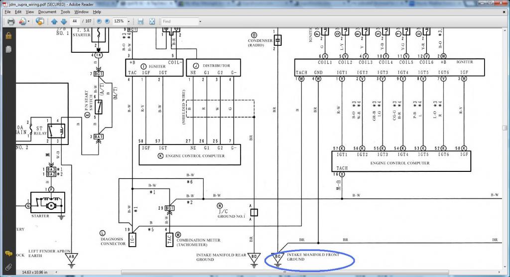
*** Knock Sensor 1 ***
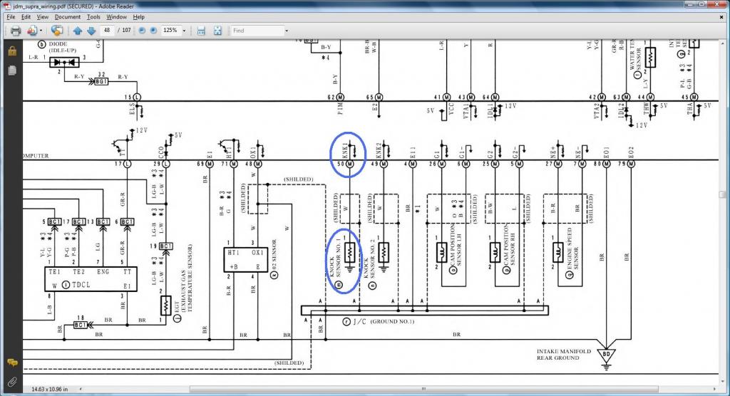
DIAGRAMS TO VERIFY WHERE A WIRE SHOULD GO IN A SC300, SC400, MKIV
*** OIL PRESSURE SENSOR***
How do we know that Pin 1 of the Oil Pressure Sensor (should go to ( SC3 IK1-20 , SC4 IK1-20 , MK4 II1-25 ) ?
SC300 - orange / SC400 - yellow ( Read the first diagram being on the right of the second so you see a continuous flow of where current flows)

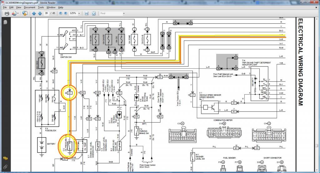
MKIV
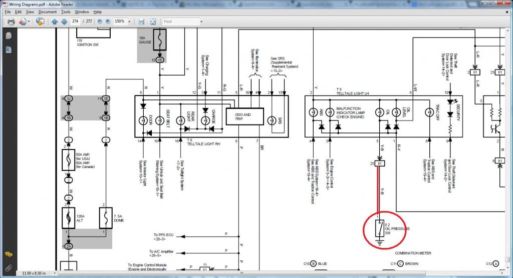
*** AC Compressor Plug ***
How do we know which plugs the wires of the AC Compressor Plug goes ?
Pin 1 of AC Compressor plug (should go to (SC3 EB1-7 & II1-1 , SC4 ED1-8 then to EB1-7 & II1-1 , MK4 II1-26 ))
Pin 2 of AC Compressor plug (should go to (SC3 II1-4 , SC4 ED1-4 then to II1-4 , MK4 II1-20 ))
Pin 4 of AC Compressor plug (should go to (SC3 EB1-1 , SC4 ED2-1 then to EB1-1 , MK4 EA1-1 & II1-10 ))
SC300 - orange / SC400 - yellow ( Read the first diagram being on the right of the second so you see a continuous flow of where current flows)
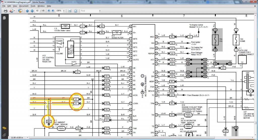
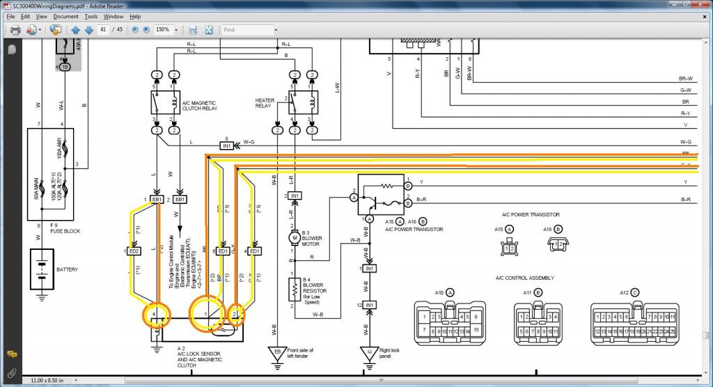
MKIV
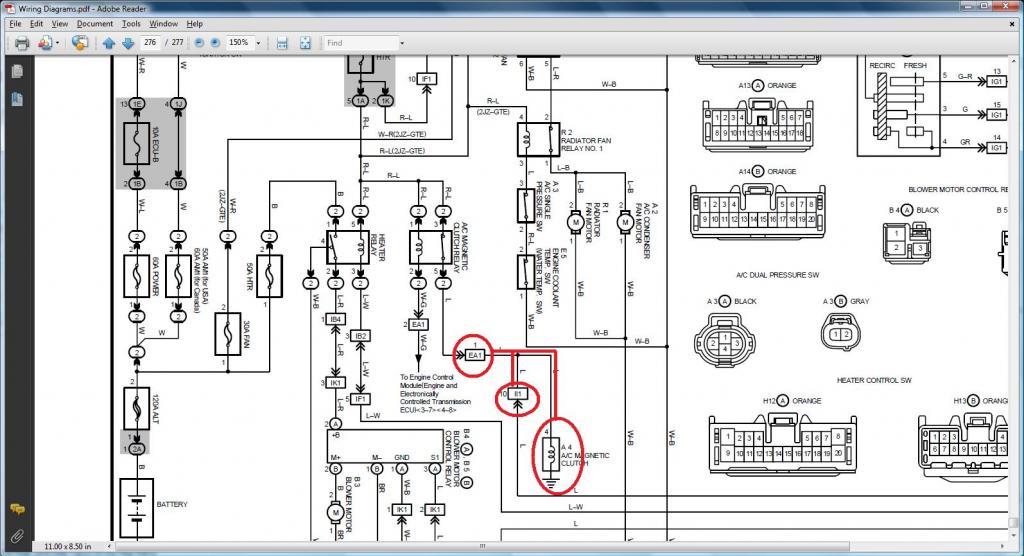
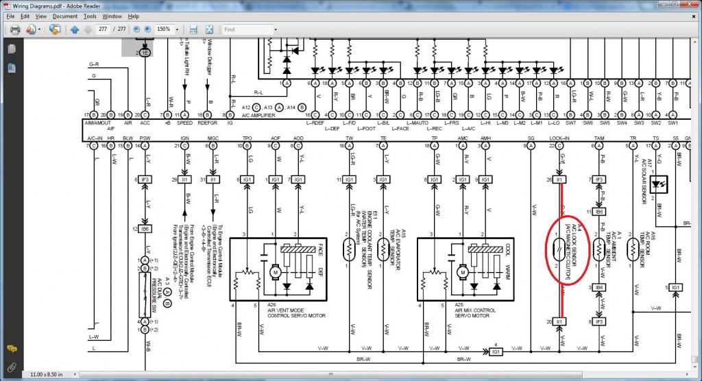
*** LOW OIL LEVEL SENSOR ***
How do we know which plugs the wires for the Oil Level Sensor goes ?
Pin 1 of Low Level Oil Sensor (should go to SC3 IK2-10 , SC4 IK2-10 , MK4 II1-33 )
Pin 2 of Low Level Oil Sensor (should go to (SC3 Rear Side Ground of Intake Manifold , SC4 Rear Side Ground of the Intake Manifold , MK4 Rear Side Ground of Intake Manifold)
SC300 - orange / SC400 - yellow ( Read the first diagram being on the right of the second so you see a continuous flow of where current flows)
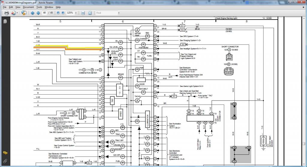
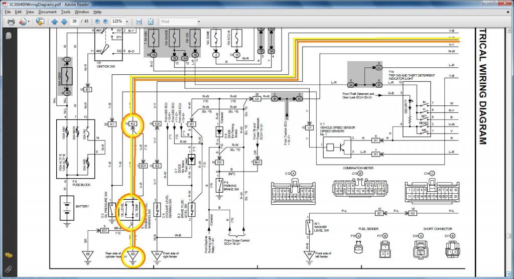
MKIV
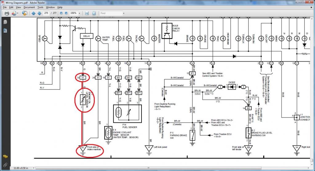

Last edited by gerrb; 02-01-14 at 05:22 AM.
01-31-14, 04:33 PM
#45
Now let's work on the next set of connectors

This is the Diagnostic port . Underneath the cover you have a diagram that labels each pin.
The INFO you need to do THE DRILL .
1) Knock Sensor 2
Pin 1 of Knock Sensor 2 goes to pin 49 of 80 pin the ECU Connector
2) Starter
Pin 1 of Starter goes to pin 1 of Plug F of Big Gray Aristo Plug (should go to (SC3 EB2-1 , SC4 EB2-1 , MK4 EA3-1 ))
3) VSVEVAP ( Canister Purge )
Pin 1 of VSVEVAP goes to Pin 1 of VSV1 , VSV2 , VSV3 , VSVPMC (& should go to Pin 12 of the Data Link Connector & to ( SC3 IJ1-12 & EB2-1 & Short-4 , SC4 IJ1-12 & EB2-3 , MK4 EA3-3 ))
Pin 2 of VSVEVAP goes to Pin 74 of the 80 pin ECU Connector
4) Rear Intake Manifold Ground
Rear Intake Manifold Ground goes to Pin 69 & Pin 79 & Pin 80 of the 80 pin ECU Connector
5)Diagostic Port
Pin 1 (FP) of Diagnostic Port goes to Pin 15 of Plug C of the Big Gray Aristo Plug (should go to (SC3 IJ1-1 , SC4 IJ1-1 , MK4 IJ1-8 ))
Pin 2 (W) of Diagnostic Port goes to Pin 2 of Plug E of the Big Gray Aristo Plug (should go to Pin 6 of the 40 pin ECU Connector & to (SC3 IK2-9 , SC4 IK2-9 , MK4 II1-15 ))
Pin 3 (E1) of Diagnostic Port goes to Pin 11 of Plug F of the Big Gray Aristo Plug (should go to Rear Intake Manifold Ground & to (SC3 Pin 69,79,80 of the 80 pin ECU Connector , SC4 IK1-1 & Pin 69,79,80 of the 80 pin ECU Connector , MK4 IJ1-18 ))
Pin 4 (OX1) of Diagnostic Port goes to Pin 48 of the 80 pin ECU Connector
Pin 5 (AB) of Diagnostic Port goes to Pin 4 of Plug D of the Big Gray Aristo Plug
Pin 6 (OP1) of Diagnostic Port goes to Pin 10 of Plug D of the Big Gray Aristo Plug
Pin 7 (CCo) of Diagnotic Port goes to Pin 8 of Plug D of the Big Gray Aristo Plug
Pin 8 (TE1) of Diagnostic Port goes to Pin 4 of Plug F of the Big Gray Aristo Plug (should go to Pin 20 of the 40 pin ECU Connector & to ( SC3 IK1-4 , SC4 IK1-4 , MK4 IJ1-5 ))
Pin 9 (TE2) of Diagnostic Port goes to Pin 7 of Plug E of the Big Gray Aristo Plug (should go to Pin 19 of the 40 pin ECU Connector & to ( SC3 IK1-2 , SC4 IK1-2 , MK4 IJ1-17 ))
Pin 11 (TC) of Diagnostic Port goes to Pin 6 of Plug E of the Big Gray Aristo Plug
Pin 12 (+B) of Diagnostic Port goes to Pin 3 of Plug E of the Big Gray Aristo Plug (should go to (SC3 IJ1-12 & EB2-1 & Short-4 & Pin 2 of O2 Sensor , SC4 IJ1-12 & EB2-3 & Pin 2 of O2 Sensor , MK4 EA3-3 & Pin 31 of 40 pin ECU Connector ))
Pin 13 (VF1) of Diagnostic Port goes to Pin 10 of Plug F of the Big Gray Aristo Plug (should go to Pin 29 of the 80 pin ECU Connector & to ( SC3 IK1-3 , SC4 IK1-3 , MK4 IJ1-13 ))
Pin 16 (TS) of Diagnostic Port goes to Pin 5 of Plug F of the Big Gray Aristo Plug
Pin 18 (TEM) of Diagnostic Port goes to Pin 5 of Plug D of the Big Gray Aristo Plug
Pin 19 (IG-) of Diagnostic Port goes to Pin 1 of the 4 pin Igniter Connector
Pin 22 (WA) of Diagnostic Port goes to Pin 7 of Plug D of the Big Gray Aristo Plug
Pin 23 (WB) of Diagnostic Port goes to Pin 11 of Plug D of the Big Gray Aristo Plug
NOTE : Diagnostic Port pins that do not have the SHOULD GO PHRASE may or may not be used depending on your car . Please check Diagnostic Port Diagrams in the next posts.

This is the Diagnostic port . Underneath the cover you have a diagram that labels each pin.


The INFO you need to do THE DRILL .
1) Knock Sensor 2
Pin 1 of Knock Sensor 2 goes to pin 49 of 80 pin the ECU Connector
2) Starter
Pin 1 of Starter goes to pin 1 of Plug F of Big Gray Aristo Plug (should go to (SC3 EB2-1 , SC4 EB2-1 , MK4 EA3-1 ))
3) VSVEVAP ( Canister Purge )
Pin 1 of VSVEVAP goes to Pin 1 of VSV1 , VSV2 , VSV3 , VSVPMC (& should go to Pin 12 of the Data Link Connector & to ( SC3 IJ1-12 & EB2-1 & Short-4 , SC4 IJ1-12 & EB2-3 , MK4 EA3-3 ))
Pin 2 of VSVEVAP goes to Pin 74 of the 80 pin ECU Connector
4) Rear Intake Manifold Ground
Rear Intake Manifold Ground goes to Pin 69 & Pin 79 & Pin 80 of the 80 pin ECU Connector
5)Diagostic Port
Pin 1 (FP) of Diagnostic Port goes to Pin 15 of Plug C of the Big Gray Aristo Plug (should go to (SC3 IJ1-1 , SC4 IJ1-1 , MK4 IJ1-8 ))
Pin 2 (W) of Diagnostic Port goes to Pin 2 of Plug E of the Big Gray Aristo Plug (should go to Pin 6 of the 40 pin ECU Connector & to (SC3 IK2-9 , SC4 IK2-9 , MK4 II1-15 ))
Pin 3 (E1) of Diagnostic Port goes to Pin 11 of Plug F of the Big Gray Aristo Plug (should go to Rear Intake Manifold Ground & to (SC3 Pin 69,79,80 of the 80 pin ECU Connector , SC4 IK1-1 & Pin 69,79,80 of the 80 pin ECU Connector , MK4 IJ1-18 ))
Pin 4 (OX1) of Diagnostic Port goes to Pin 48 of the 80 pin ECU Connector
Pin 5 (AB) of Diagnostic Port goes to Pin 4 of Plug D of the Big Gray Aristo Plug
Pin 6 (OP1) of Diagnostic Port goes to Pin 10 of Plug D of the Big Gray Aristo Plug
Pin 7 (CCo) of Diagnotic Port goes to Pin 8 of Plug D of the Big Gray Aristo Plug
Pin 8 (TE1) of Diagnostic Port goes to Pin 4 of Plug F of the Big Gray Aristo Plug (should go to Pin 20 of the 40 pin ECU Connector & to ( SC3 IK1-4 , SC4 IK1-4 , MK4 IJ1-5 ))
Pin 9 (TE2) of Diagnostic Port goes to Pin 7 of Plug E of the Big Gray Aristo Plug (should go to Pin 19 of the 40 pin ECU Connector & to ( SC3 IK1-2 , SC4 IK1-2 , MK4 IJ1-17 ))
Pin 11 (TC) of Diagnostic Port goes to Pin 6 of Plug E of the Big Gray Aristo Plug
Pin 12 (+B) of Diagnostic Port goes to Pin 3 of Plug E of the Big Gray Aristo Plug (should go to (SC3 IJ1-12 & EB2-1 & Short-4 & Pin 2 of O2 Sensor , SC4 IJ1-12 & EB2-3 & Pin 2 of O2 Sensor , MK4 EA3-3 & Pin 31 of 40 pin ECU Connector ))
Pin 13 (VF1) of Diagnostic Port goes to Pin 10 of Plug F of the Big Gray Aristo Plug (should go to Pin 29 of the 80 pin ECU Connector & to ( SC3 IK1-3 , SC4 IK1-3 , MK4 IJ1-13 ))
Pin 16 (TS) of Diagnostic Port goes to Pin 5 of Plug F of the Big Gray Aristo Plug
Pin 18 (TEM) of Diagnostic Port goes to Pin 5 of Plug D of the Big Gray Aristo Plug
Pin 19 (IG-) of Diagnostic Port goes to Pin 1 of the 4 pin Igniter Connector
Pin 22 (WA) of Diagnostic Port goes to Pin 7 of Plug D of the Big Gray Aristo Plug
Pin 23 (WB) of Diagnostic Port goes to Pin 11 of Plug D of the Big Gray Aristo Plug
NOTE : Diagnostic Port pins that do not have the SHOULD GO PHRASE may or may not be used depending on your car . Please check Diagnostic Port Diagrams in the next posts.
Last edited by gerrb; 02-04-14 at 01:21 AM.