
sc300 triple pump in-tank installation
 12-10-11, 10:20 AM
#1
Lead Lap
Thread Starter
Recently, I finished a direct-port nitrous installation on my DaveH intake:
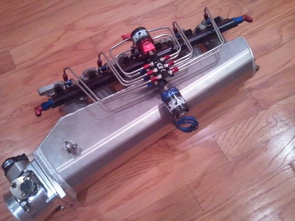
The kit supports up to a 350 shot; however, I won't use more than the 225 hp nozzles.
Anyway, this obviously requires more fuel, but installing a third pump in the OEM tank is a bit tricky. So, I wanted to show how I set it up. I'm sure there are other ways to install the pumps; so, please don't treat the following approach as the only solution. In fact, I welcome suggestions on how to improve this setup.
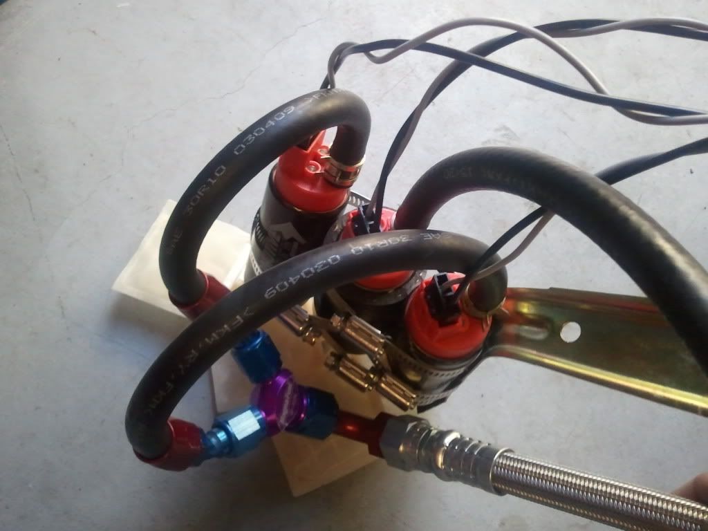
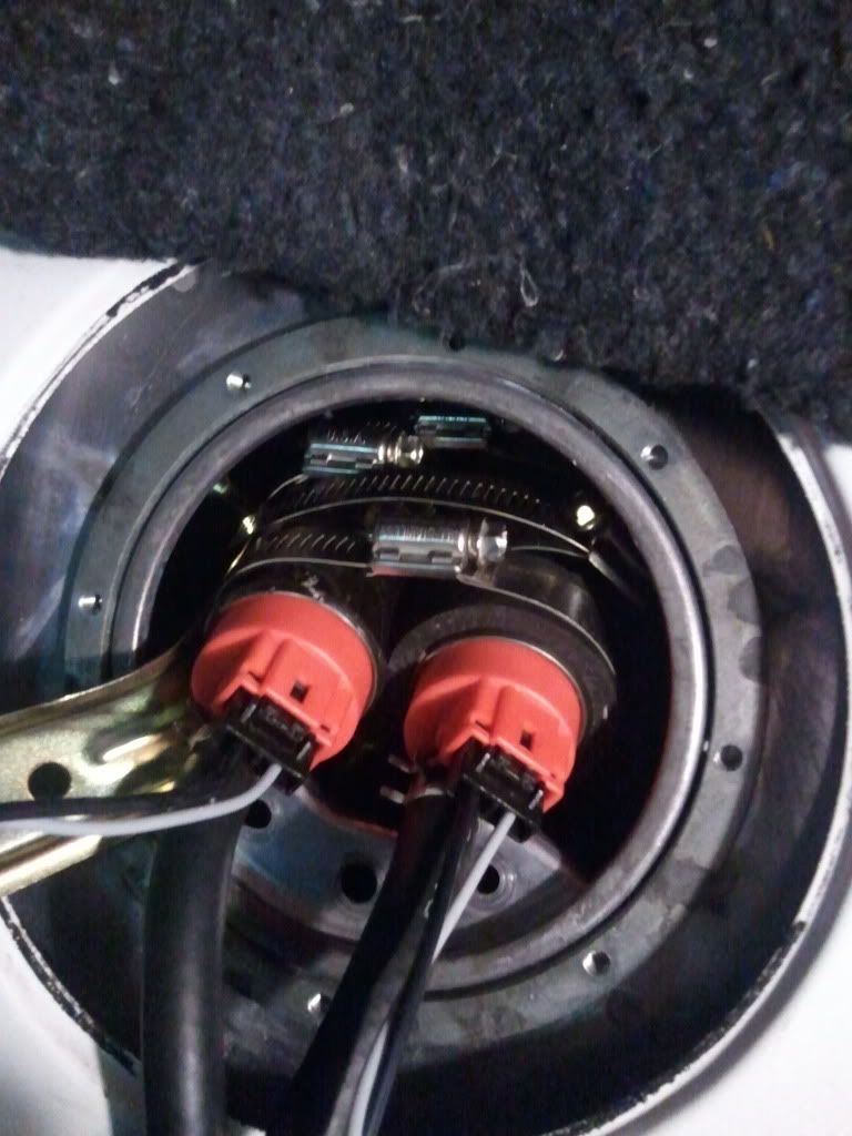
First, are a couple pics of how the pumps will be installed in the tank. I elected to go with the Aeromotive 340 Stealth pumps because they flow more than Denso's, take less current, and have a turbine design that will permit PWM operation which I'll talk about later.
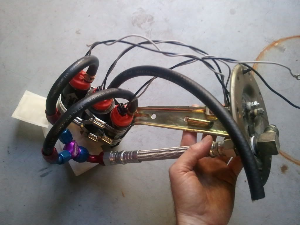
The pumps are fixed in place with worm gear clamps but are insulated from vibration using circular strips of rubber I cut from fuel tank filler hose. I've used this hose in the past to insulate the pumps and have had no issues with the rubber degrading now after 10 years of use.
The configuration uses a small Magnafuel Y-block (two 6AN to 8AN), and two 30 degree 6-an fittings pressed on SAE J30R10 5/16" in-tank fuel line.
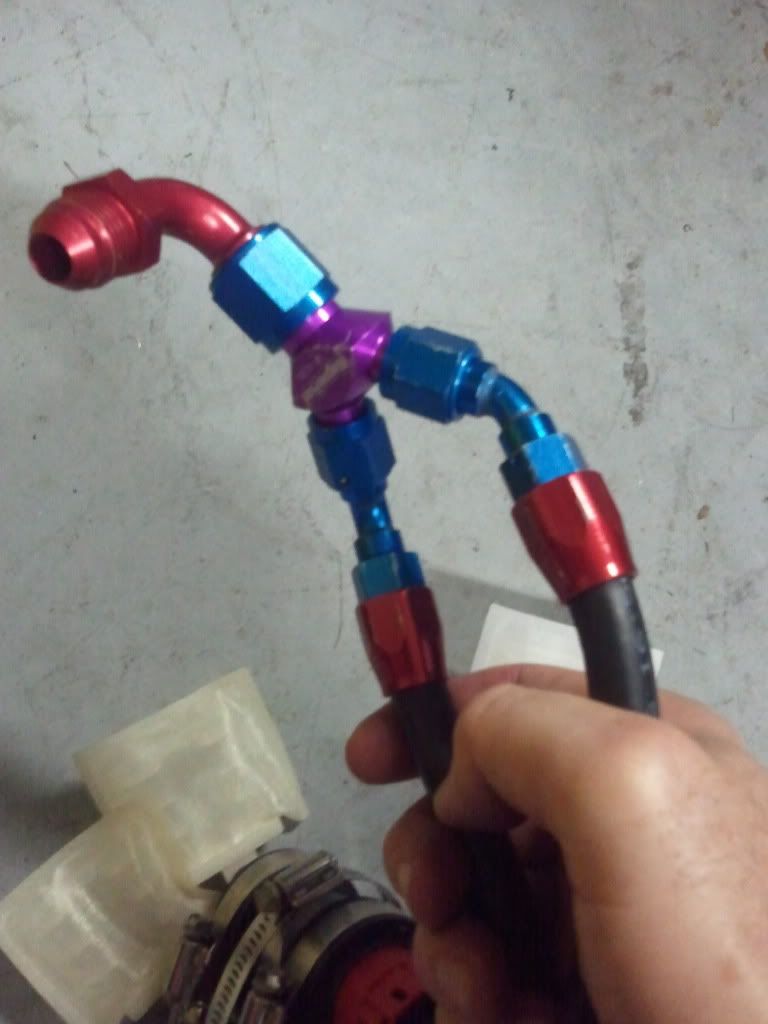
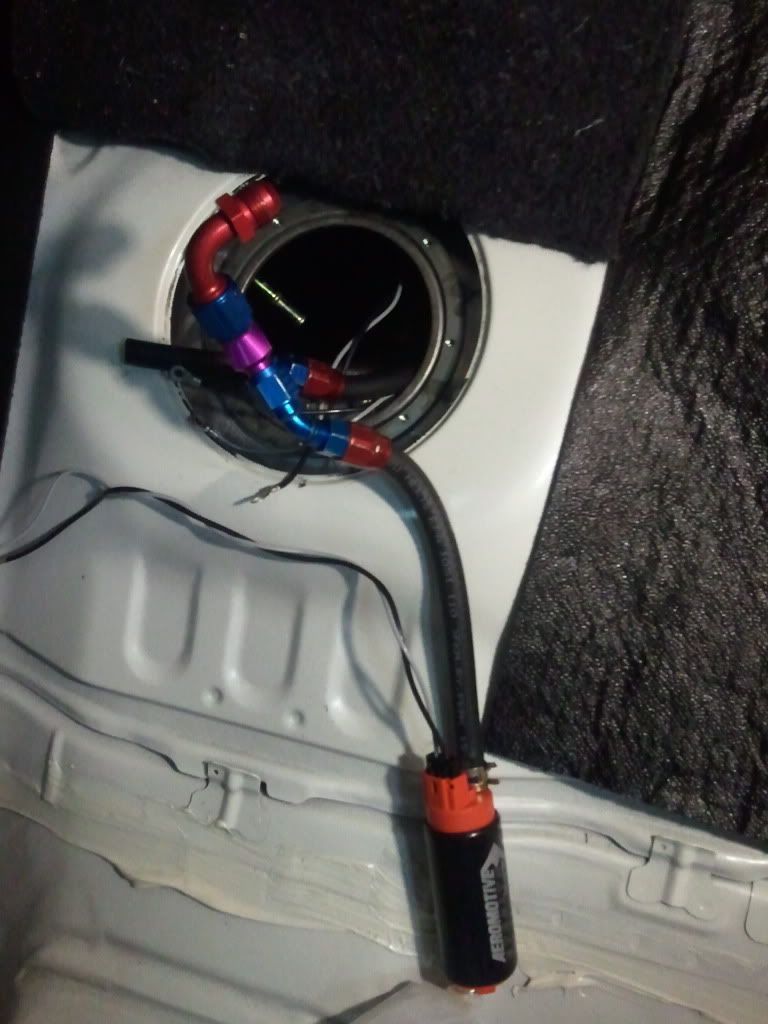
The Y-block feeds a 90 deg 8AN fitting which is attached to an 8AN steel-braided teflon line that's 8" long:
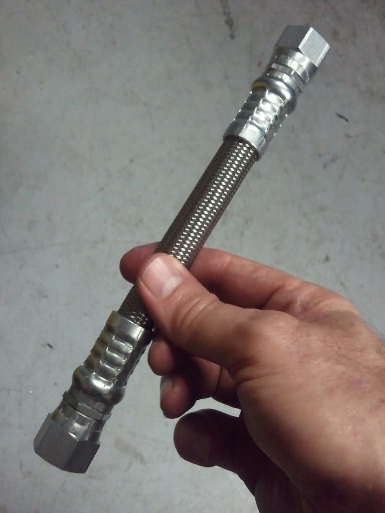
I chose a teflon line because I'm converting the fuel system to E85 and want to ensure the hose doesn't degrade in the tank. The teflon line attaches to a 90 8AN steel bulkhead fitting that is screwed into the tank access plate with a welded bolt on the back side.
When sizing the in-tank line, you'll need to stagger the line lengths to get the Y-block facing towards the access plate. It's no coincidence that the line on the top is shorter than the line on the bottom in the pic above.
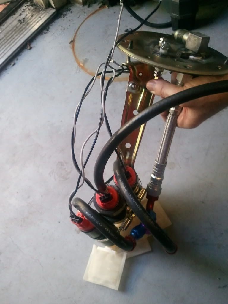
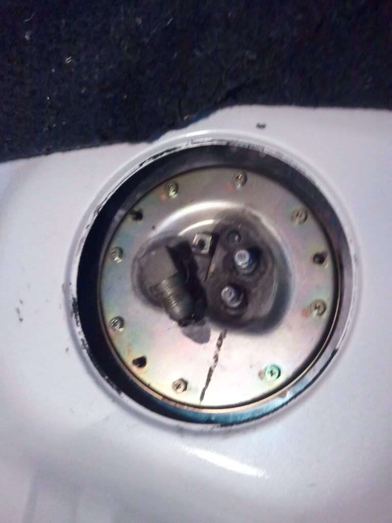
When installing the pumps, you can only get two into the tank at once, and the clamp for the third pump must be tightened so that it fits through the access hole, as well. Here's a pic showing the first two pumps with the third removed and the clamp for the third pump tightened down.
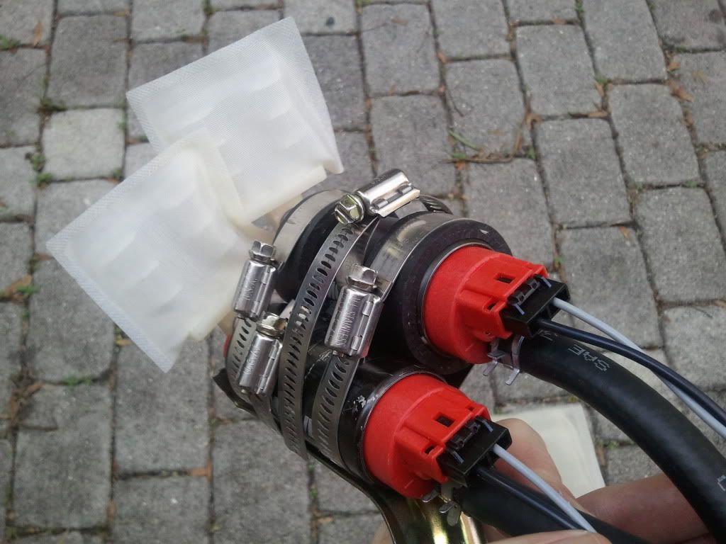
Then, the two pumps will easiy fit into the access hole.
The third pump just hangs outside until it's ready to go in.
Once the two pumps are in the tank, I reached in with socket wrench and loosened the clamp for the third pump. Then I fed the pump into the open clamp, filter-first, and positioned it as shown in the first couple of pics above. Oviously, the clamp must then be tightened to secure the third pump in place.
Next, I pulled the Y-block out of the tank and screwed on the teflon line.
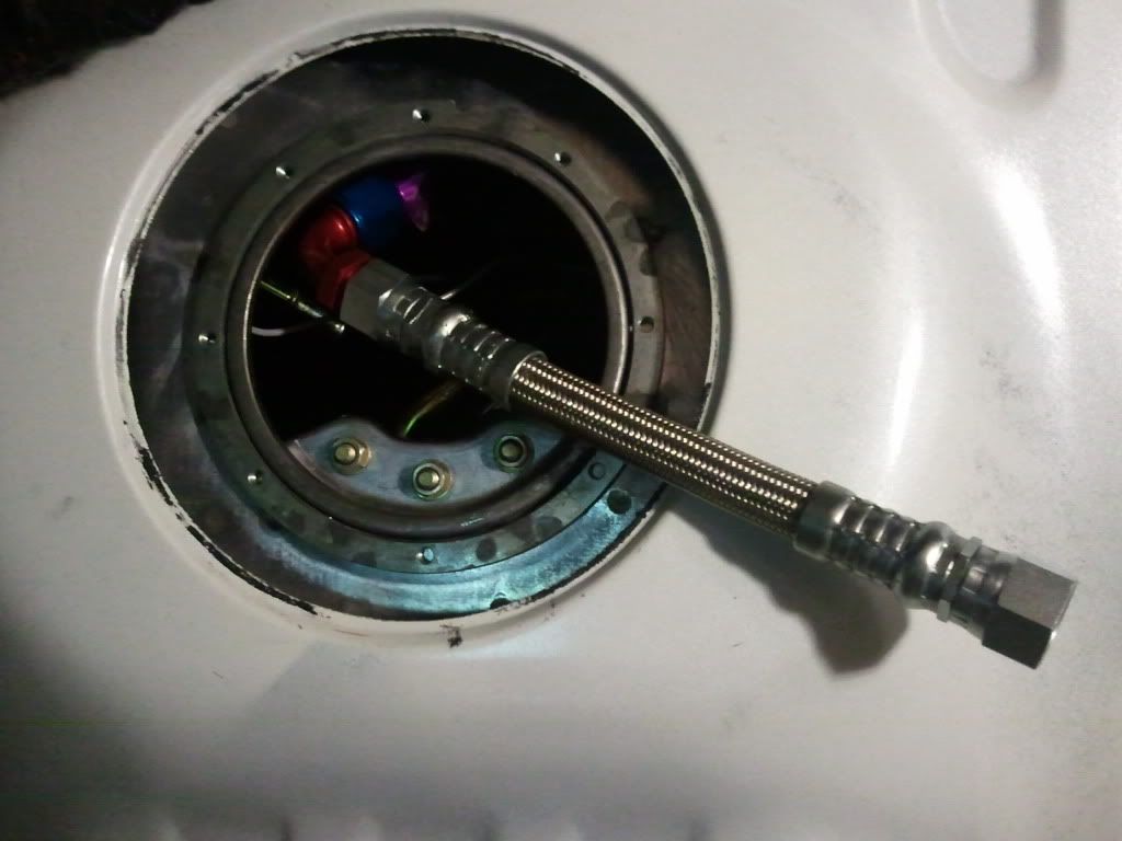
It easily feeds back into the tank.
Before closing up the tank, the pump with the single fuel line is cut to length and attached to the OEM feed line which I'll Y-block with the 8AN line outside of the tank in the engine bay. The only thing left to do is wire up the pumps and bolt on the teflon line to the bulkhead fitting.
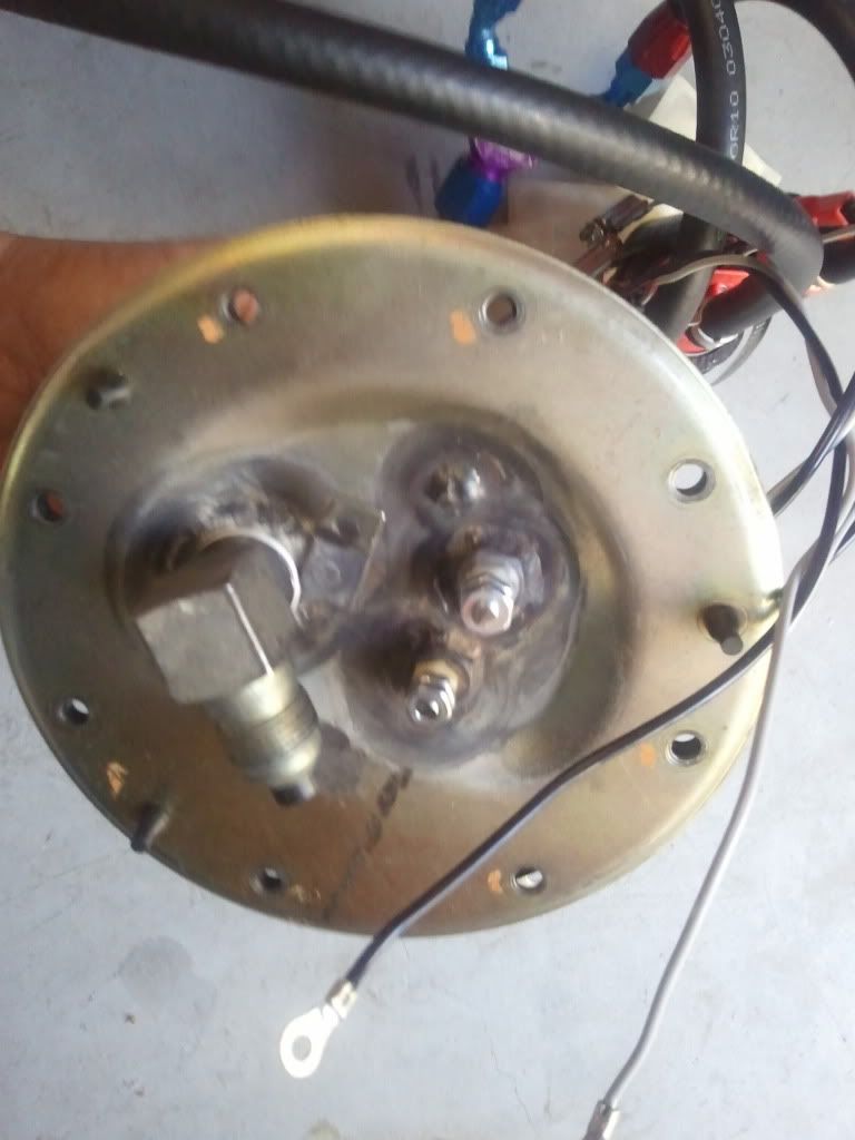
Ok... just a few notes. I had to cut-to-length new teflon insulated wires for the pumps; the ones that come with the pumps aren't long enough to wire the pumps with room to tighten the 8AN line to the bulkhead fitting with the access plate extended away from the tank. Also, make sure you have the worm gear clamp for the third pump oriented like I've shown; otherwise you won't be able to get to it with a wrench when securing the last pump in the tank.
You also might ask why there are only two positive posts to power three pumps. Two pumps are driven together from the post on the top; the third pump has its own terminal. As mentioned earlier, I plan on driving two pumps using PWM control; this will allow me to control flow to the fuel rail when there isn't much load on the motor. Plus, I plan on using the OEM return line, and I don't want to overrun the return with two pumps on at full duty when the motor is in vacuum.
That's about it. I'll keep the forum posted on how it works. Also, if you have any suggestions for improvement, comments are greatly appreciated.
Thanks,
-scott
The kit supports up to a 350 shot; however, I won't use more than the 225 hp nozzles.
Anyway, this obviously requires more fuel, but installing a third pump in the OEM tank is a bit tricky. So, I wanted to show how I set it up. I'm sure there are other ways to install the pumps; so, please don't treat the following approach as the only solution. In fact, I welcome suggestions on how to improve this setup.
First, are a couple pics of how the pumps will be installed in the tank. I elected to go with the Aeromotive 340 Stealth pumps because they flow more than Denso's, take less current, and have a turbine design that will permit PWM operation which I'll talk about later.
The pumps are fixed in place with worm gear clamps but are insulated from vibration using circular strips of rubber I cut from fuel tank filler hose. I've used this hose in the past to insulate the pumps and have had no issues with the rubber degrading now after 10 years of use.
The configuration uses a small Magnafuel Y-block (two 6AN to 8AN), and two 30 degree 6-an fittings pressed on SAE J30R10 5/16" in-tank fuel line.
The Y-block feeds a 90 deg 8AN fitting which is attached to an 8AN steel-braided teflon line that's 8" long:
I chose a teflon line because I'm converting the fuel system to E85 and want to ensure the hose doesn't degrade in the tank. The teflon line attaches to a 90 8AN steel bulkhead fitting that is screwed into the tank access plate with a welded bolt on the back side.
When sizing the in-tank line, you'll need to stagger the line lengths to get the Y-block facing towards the access plate. It's no coincidence that the line on the top is shorter than the line on the bottom in the pic above.
When installing the pumps, you can only get two into the tank at once, and the clamp for the third pump must be tightened so that it fits through the access hole, as well. Here's a pic showing the first two pumps with the third removed and the clamp for the third pump tightened down.
Then, the two pumps will easiy fit into the access hole.
The third pump just hangs outside until it's ready to go in.
Once the two pumps are in the tank, I reached in with socket wrench and loosened the clamp for the third pump. Then I fed the pump into the open clamp, filter-first, and positioned it as shown in the first couple of pics above. Oviously, the clamp must then be tightened to secure the third pump in place.
Next, I pulled the Y-block out of the tank and screwed on the teflon line.
It easily feeds back into the tank.
Before closing up the tank, the pump with the single fuel line is cut to length and attached to the OEM feed line which I'll Y-block with the 8AN line outside of the tank in the engine bay. The only thing left to do is wire up the pumps and bolt on the teflon line to the bulkhead fitting.
Ok... just a few notes. I had to cut-to-length new teflon insulated wires for the pumps; the ones that come with the pumps aren't long enough to wire the pumps with room to tighten the 8AN line to the bulkhead fitting with the access plate extended away from the tank. Also, make sure you have the worm gear clamp for the third pump oriented like I've shown; otherwise you won't be able to get to it with a wrench when securing the last pump in the tank.
You also might ask why there are only two positive posts to power three pumps. Two pumps are driven together from the post on the top; the third pump has its own terminal. As mentioned earlier, I plan on driving two pumps using PWM control; this will allow me to control flow to the fuel rail when there isn't much load on the motor. Plus, I plan on using the OEM return line, and I don't want to overrun the return with two pumps on at full duty when the motor is in vacuum.
That's about it. I'll keep the forum posted on how it works. Also, if you have any suggestions for improvement, comments are greatly appreciated.
Thanks,
-scott
Last edited by motorheaddown; 12-10-11 at 11:31 AM.
 12-16-11, 10:56 AM
#5
Lead Lap
Thread Starter
With the setup above, only one addition -8 feed line is required, and I'm utilizing both the OEM feed and return lines on a fuel system that will support over 1000whp. Additionally, the pumps are staged so they're not constanting recirculating fuel back to the tank, and they're VERY quiet.
Now, the downside is the complexity of the fuel system and higher chance of pump failure which is most critical under high boost. However, if the pumps fail under normal operating conditions, I can make it home if one or two pumps fail.
Thanks,
-scott
12-16-11, 08:34 PM
#6
Good question... First, I had all the plumbing in place to support 3-pump operation. Plus, a single pump like a Weldon is VERY loud and requires an aftermarket return line.
With the setup above, only one addition -8 feed line is required, and I'm utilizing both the OEM feed and return lines on a fuel system that will support over 1000whp. Additionally, the pumps are staged so they're not constanting recirculating fuel back to the tank, and they're VERY quiet.
Now, the downside is the complexity of the fuel system and higher chance of pump failure which is most critical under high boost. However, if the pumps fail under normal operating conditions, I can make it home if one or two pumps fail.
Thanks,
-scott

Trending Topics
01-03-12, 07:30 AM
#9
Lead Lap
Thread Starter

 01-05-12, 02:48 PM
#11

i'm curious as to why you didn't use a 3-way "Y" in the tank, instead of running one pump separately and Y'ing it in up in the engine bay...
i understand the concept of over-running the rail so your fuel pressure isn't controllable at low load, but you could still run one pump 99% of the time (and the other two as a PWM output) and have it feed all through the same -8 line, correct? it seems to me like you're just adding extra fuel line and an additional "Y" when it's not necessary.
(i'm not hating here, just curious -- maybe i'm missing something)
 Is there any room for FUEL in the tank with all that gear? :P
