When you click on links to various merchants on this site and make a purchase, this can result in this site earning a commission. Affiliate programs and affiliations include, but are not limited to, the eBay Partner Network.
I currently have a mobius action cam plugged into my cigarette lighter. This camera is small and turns on automatically with power. I want to mount it up high in the windshield and wire it up to switched 12 volts up in the panel where the moonroof/dome light/homelink is. I figure the moonroof must have switched 12V power since it only works when the ignition switch is on.
So this weekend I took that panel off and could not figure out what wire has the power I want, there are too many wires up there and none looks larger than the other (like it would actually carry power rather than signal a relay or something.
Does anyone have a wire diagram of that area that shows what to tap into to provide miniscule power to a dash cam?
Be aware that the wiring was designed to handle loads specific to the original function. Adding additional equipment on a circuit may cause an overload or in the worst case a possible fire. I have seen wires melt without popping the fuse. It's not the volts it is the amperage you need to consider. I think it would be safer and more reliable if you ran your own hot / positive rather then tap into the existing wire. The existing ground is not a problem to use
I agree with Lavrishevo. Fuses are sized to protect the wire, so I wouldn't up-size the fuse for your installation. In the unlikely case if your additional device blows the 30A fuse, it is drawing more current than the wire is designed for. Having said all that, please proceed at your own risk.
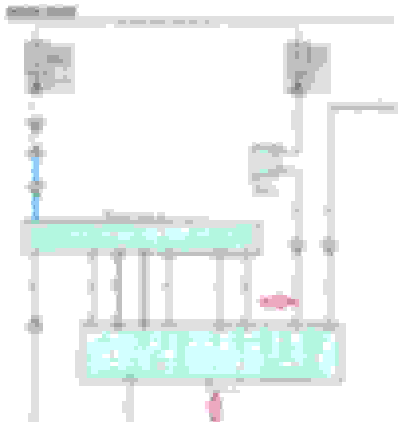
Here is the wiring diagram for your moon roof wiring. Please refer to the red arrows, the Blue (L) wiring is your positive and the White/Black (W-B) is your negative. I've also include the sketch with the location of M6.
Many thanks RKW!! This is exactly what I believe I need.
I think M6 remains with the car when the overhead panel is removed and O6 is attached to the removable panel. There is another larger ECU on that removable panel that is not on this diagram. In the diagram you provided it seems like these other boxes might be the rain sensor or homelink controllers. I provided a picture of the top side of this panel. Funny that MAYDAY is printed on this board but LexusLink is not available. Also provided is the $3 WalMart USB power supply I intend to use to convert car 12V to camera 5V..
The camera draws max 0.4A which should be unnoticeable on a 30A fused supply. I will provide photos and additional info as I proceed with this little weekend project.
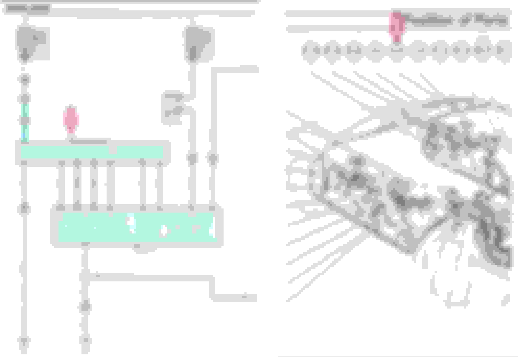
Here's the full page of the connector location with description. I also included a drawing of the M6 connector. Terminal 5 is positive, and 7 is negative. Hope these help!
.4A draw for the camera will not cause any blown fuse or current overload causing melted wires. The wire gauge, max amp load and fuse tolerance would not be exceeded by a persistent .4A draw.
.4A draw for the camera will not cause any blown fuse or current overload causing melted wires. The wire gauge, max amp load and fuse tolerance would not be exceeded by a persistent .4A draw.
My original precautionary comment was not intended for normal operation of the camera, which as you pointed out, only draws 0.4A.
It’s important to remember that fuses are sized to protect the wires downstream of it. Let’s supposed that the camera wires, which are sized to carry 0.4A, suffer a partial short (for example, a defective electronics in the camera). The 30A fuse, which in theory sized for 75 times the current flow (30 divided by 0.4) will not immediately blow and will allow up to 30A of current to flow through the wires designed for 0.4A. This can easily turn the camera wires into a heating element – a potential fire hazard.
Chunkyda seems to be well versed on automotive power and electronics, and I'm sure he has already planned to add an inline fuse (say, 1A) at the splice. Safety is important, thus the comment "proceed at your own risk".
If there's a continuing safety concern or perceived risk tapping into existing overhead wiring for a .4 amp 5-volt accessory despite the use of the factory inline low-amp separate camera fuse, wire the + side of the camera directly to one of the junction blocks (located on either side of the upper foot wells) using a dedicated wire of at least 16 ga. There are unused terminals (no fuse inserted) at the junction block.
I just might have to run a wire up there from the footwell. It seems the blue wire I had intended to splice into is always hot. I had hoped that since the sunroof only works when ignition is on that power wire would be wired to the ignition on position.
I could put a manual switch into my camera circuit but that would defeat the intent which is to have something automatically record when the car is on. Of course there is a on button on the camera too but for the same reason I want it to be automatic.
So next question for the community is what about the air bags in the A-pillars, can that trim be removed to run a wire up to the roof w/o affecting airbag operation?
I did not read your original post carefully about needing a switched 12V power source - I apologize. No problem, you're in luck because you can tap into switched 12V power at the Overhead J/B "O6". Just look for two light green wires with red stripe (LG-R), pick one of them! Refer to red arrows on schematic below and give it a try...
Here is the wiring diagram. The 7.5A fuse "P-IG" is switched by a relay "P-IG1". Both are located at the Passenger Side J/B. You can tap into either of the LG-R (light green - red) wires from the Overhead J/B "O6" terminal 26 or 27.
 09-09-14, 12:46 PM