DIY Valentine V1 radar detector hardwire 2001 LS430
 06-07-11, 05:52 AM
#1
Driver School Candidate
Thread Starter

After years of receiving invaluable info from members on this site I finally had the opportunity to undertake a task and create a DIY for something I could not find - hardwiring a Valentine V1 radar detector into a 2001 LS430.
This job was actually pretty simple - you just have to be careful that you don't scratch that trim, or inadvertently damage any wires. This was my experience with my LS 430, please perform this modification at your own risk - I am not responsible for any damage caused by following these steps. Let's get started:
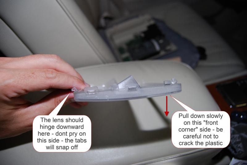
Remove the dome light lens
Using a very small flat screwdriver with the end taped so you don't scratch any plastic, pry the clear plastic lens from the upper console starting on either corner on the edge indicated by the yellow arrow. Once you have freed the tabs, pull down from the edge indicated by the yellow arrow - be careful not to crack the plastic. The opposite side from the yellow arrow (near the Homelink buttons) should hinge downward and then you can remove the dome light lens.

Remove the upper console
Once the clear lens has been removed, the upper console can be unscrewed. There are four screws that need to be removed before you can pry the upper console down. There are two small plastic tabs covering the two screws in the sunglasses compartment that need to be pried downward to access the screws. Once the four screws have been unscrewed, the console can be pried downward from the Homelink edge as indicated by the yellow arrow. The non Homelink edge has tabs that will break if you try to pry downward.


Once you pry down the upper console, the white 32 pin connector plug needs to be disconnected from the console.

Press the release tab on the white connector plug and wiggle the plug out. The upper console can now be completely detached and set aside.
Please see second post for the remainder of the DIY -
Attached Images
This job was actually pretty simple - you just have to be careful that you don't scratch that trim, or inadvertently damage any wires. This was my experience with my LS 430, please perform this modification at your own risk - I am not responsible for any damage caused by following these steps. Let's get started:
Remove the dome light lens
Using a very small flat screwdriver with the end taped so you don't scratch any plastic, pry the clear plastic lens from the upper console starting on either corner on the edge indicated by the yellow arrow. Once you have freed the tabs, pull down from the edge indicated by the yellow arrow - be careful not to crack the plastic. The opposite side from the yellow arrow (near the Homelink buttons) should hinge downward and then you can remove the dome light lens.
Remove the upper console
Once the clear lens has been removed, the upper console can be unscrewed. There are four screws that need to be removed before you can pry the upper console down. There are two small plastic tabs covering the two screws in the sunglasses compartment that need to be pried downward to access the screws. Once the four screws have been unscrewed, the console can be pried downward from the Homelink edge as indicated by the yellow arrow. The non Homelink edge has tabs that will break if you try to pry downward.
Once you pry down the upper console, the white 32 pin connector plug needs to be disconnected from the console.
Press the release tab on the white connector plug and wiggle the plug out. The upper console can now be completely detached and set aside.
Please see second post for the remainder of the DIY -
Attached Images
Last edited by ogriebl; 06-08-11 at 10:11 AM.

 06-07-11, 09:04 AM
#3
Moderator

Great job on the captions on the clear images. Even though I'm not going to be installing a V1, these are the kind of informative things we need posted here for members.
This could also be a post on how to remove the overhead console to do the LED mod on the lighting too.
This could also be a post on how to remove the overhead console to do the LED mod on the lighting too.
06-07-11, 09:39 AM
#4
Driver School Candidate
Thread Starter
Thanks guys, I will get the rest up as soon as I can figure out how to attach more pictures. Can anyone help me with this - this is my first DIY post. Thx!

Trending Topics
06-07-11, 01:52 PM
#8
Driver School Candidate
Thread Starter
Continued from post 1
Prepare plug for tapping into power
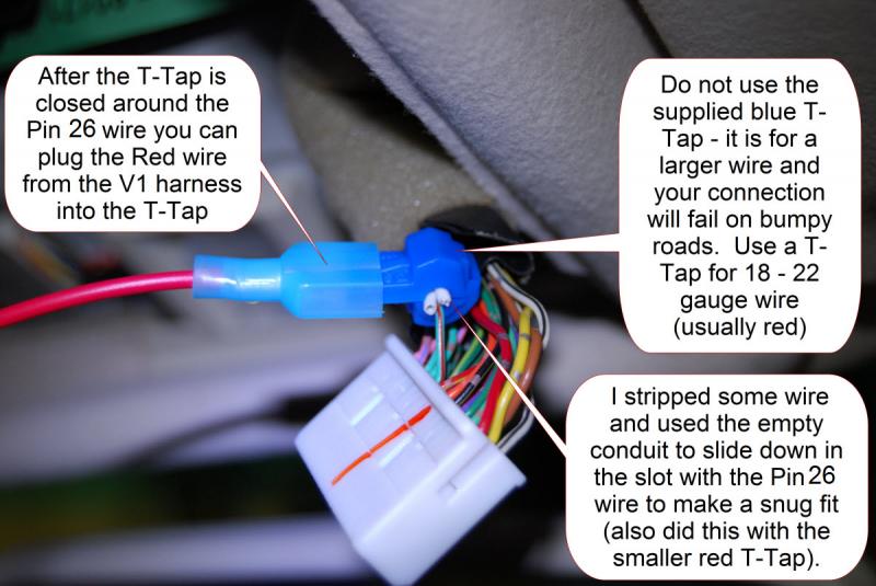
Examine the 32 pin plug and identify pin 26 � this is the wire that is light green with a red stripe next to a red wire. This wire will provide 12 volts of power and is switched so that it only supplies power when the ignition is on. Make a cut with scissors as shown where the white dotted line is so the pin 26 wire can be pulled out and away from the other wires.

Examine the T-Tap connector
The T-Tap connector supplied with the Valentine V1 is for a thicker gauge wire (14 � 16 gauge). I tried to use this connector in my initial install and found out when I was driving over bumpy roads power would intermittently disconnect. This solution is to buy the T-Tap for smaller gauge wire (18 � 22 gauge) which is typically colored red. 3M makes some (#951, 22-18) that I was able to get for free from a local audio installer � they can also be ordered online but only in larger quantities. The wire slides into the connector, and the connector slices the insulation usually on one side of the wire, making an electrical connection. From the picture you can see the slot is fairly long and I added to fill it so that the wire would not move around when everything was put back together. I strip the wire and use the insulation as the filler.

Make the power and ground connections
Slide that pin 26 wire into the slot of the T-Tap connector and slide the wire all the way to the bottom of the slot. Slide the 2 empty pieces of wire insulation down into the slot on top of the pin 26 wire and close the connector. You might have to use pliers and press until it snaps closed. Take the red male plug from the V1 harness and plug it into the T-Tap connector.
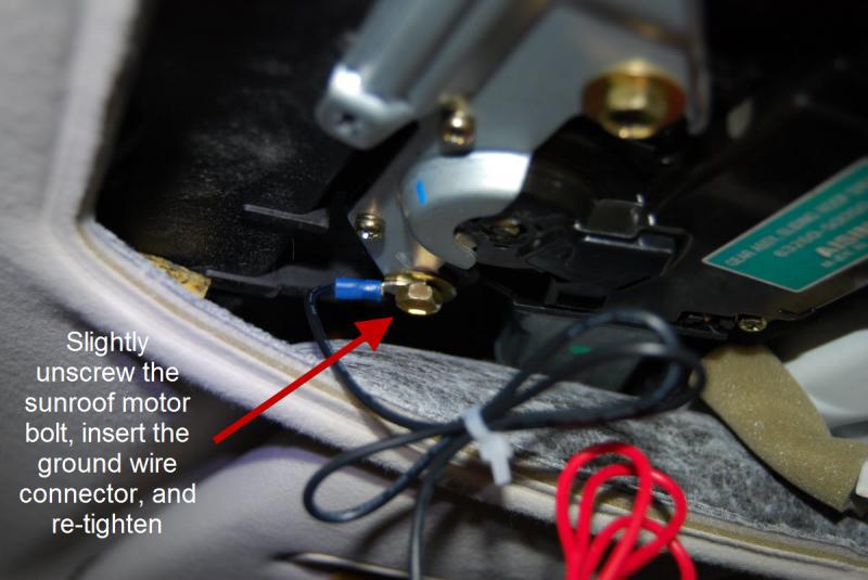
For the ground connection on the V1 wire harness, unscrew the leftmost large bolt of the sunroof motor slightly and insert the C connector plug in between the bolt and the sunroof motor and tighten.
Zip-tie both the extra power wire as well as the ground wire so that they can be neatly placed on the driver�s side of the upper console when it is back in place.
Route the red power wire under the green circuit board and around the driver side corner of the upper console as shown in the picture. Plug an RJ 11 cord into the V1 harness (the socket labeled �Main�) and let the RJ11 wire hang over the rearview mirror so that when the upper console is replaced the RJ11 wire comes into the cabin from in between the edge of the upper console and the headliner, by the windshield.
Plug in the V1 and turn the key to test for power. Wiggle the T-Tap connector to make sure it does not intermittently lose power � if it does lose power, you may need to add additional �filler� in the slot of the T-Tap connector.
Hold the upper console with all the wiring close to the opening and the headliner place the Zip-tie power and ground cords in the space on the driver�s side of the headliner hole.
Replace the upper console back into the headliner hole starting with the edge closest to the windshield. Hinge the entire upper console up until the Homelink edge snaps into place and is flush with the headliner. Hold in place while replacing the four screws.
At this point you may also want to replace the incandescent dome light bulbs with LED bulbs while you have the dome light cover off.
Replace the dome light cover by putting the tabs closest to you in the slots first (closest to the Homelink buttons), then hinge the cover up and snap in the rear piece nearest to the windshield.

Thats all folks - hope this helps!
Attached Images
Prepare plug for tapping into power
Examine the 32 pin plug and identify pin 26 � this is the wire that is light green with a red stripe next to a red wire. This wire will provide 12 volts of power and is switched so that it only supplies power when the ignition is on. Make a cut with scissors as shown where the white dotted line is so the pin 26 wire can be pulled out and away from the other wires.
Examine the T-Tap connector
The T-Tap connector supplied with the Valentine V1 is for a thicker gauge wire (14 � 16 gauge). I tried to use this connector in my initial install and found out when I was driving over bumpy roads power would intermittently disconnect. This solution is to buy the T-Tap for smaller gauge wire (18 � 22 gauge) which is typically colored red. 3M makes some (#951, 22-18) that I was able to get for free from a local audio installer � they can also be ordered online but only in larger quantities. The wire slides into the connector, and the connector slices the insulation usually on one side of the wire, making an electrical connection. From the picture you can see the slot is fairly long and I added to fill it so that the wire would not move around when everything was put back together. I strip the wire and use the insulation as the filler.
Make the power and ground connections
Slide that pin 26 wire into the slot of the T-Tap connector and slide the wire all the way to the bottom of the slot. Slide the 2 empty pieces of wire insulation down into the slot on top of the pin 26 wire and close the connector. You might have to use pliers and press until it snaps closed. Take the red male plug from the V1 harness and plug it into the T-Tap connector.
For the ground connection on the V1 wire harness, unscrew the leftmost large bolt of the sunroof motor slightly and insert the C connector plug in between the bolt and the sunroof motor and tighten.
Zip-tie both the extra power wire as well as the ground wire so that they can be neatly placed on the driver�s side of the upper console when it is back in place.
Route the red power wire under the green circuit board and around the driver side corner of the upper console as shown in the picture. Plug an RJ 11 cord into the V1 harness (the socket labeled �Main�) and let the RJ11 wire hang over the rearview mirror so that when the upper console is replaced the RJ11 wire comes into the cabin from in between the edge of the upper console and the headliner, by the windshield.
Plug in the V1 and turn the key to test for power. Wiggle the T-Tap connector to make sure it does not intermittently lose power � if it does lose power, you may need to add additional �filler� in the slot of the T-Tap connector.
Hold the upper console with all the wiring close to the opening and the headliner place the Zip-tie power and ground cords in the space on the driver�s side of the headliner hole.
Replace the upper console back into the headliner hole starting with the edge closest to the windshield. Hinge the entire upper console up until the Homelink edge snaps into place and is flush with the headliner. Hold in place while replacing the four screws.
At this point you may also want to replace the incandescent dome light bulbs with LED bulbs while you have the dome light cover off.
Replace the dome light cover by putting the tabs closest to you in the slots first (closest to the Homelink buttons), then hinge the cover up and snap in the rear piece nearest to the windshield.
Thats all folks - hope this helps!
Attached Images
Last edited by ogriebl; 06-08-11 at 10:06 AM.
06-07-11, 03:12 PM
#9
Moderator
Oh, I see where you are going with the wiring now  The final image shows the setup. I was thinking you where going to mount it on the windshield behind the rear view mirror but guess that would block the rear radar sensor.
The final image shows the setup. I was thinking you where going to mount it on the windshield behind the rear view mirror but guess that would block the rear radar sensor.
06-07-11, 03:38 PM
#10
Driver School Candidate
Thread Starter
Yeah, the RJ11 is long enough to allow mounting in a variety of positions near the rear view mirror. I am sticking with the visor clip because I want to keep the V1 as incognito as possible so I dont always have to take it down when I go shopping etc. Blendmount.com sells an adapter that will hold the V1 under the mirror - pretty nice but you can also easily spot the detector through the windshield...
 06-11-11, 11:36 PM
#13
Driver School Candidate

Join Date: Apr 2011
Location: Nevada
Posts: 5
Likes: 0
Received 0 Likes
on
0 Posts
I have a 2006 LS430 and used an invisicord (invisicord.com)to wire an Escort Redline to the power and ground connectors for the mirror. The cord is designed to be inserted into the back of connectors and mine fit great. I do not have Lexus Link so the wiring above the lamp panel is quite simple. I have the factory maintenance manual and simply followed the procedure for testing the mirror. The diagrams on pages 70-44 through 70-46 make it a simple process. I bought my manual on a CD via ebay. You might also try to get your dealer to copy those pages. I keep the Redline on the visor all of the time because you can't really notice it from outside. It works great up there.
03-21-16, 01:38 PM
#14
Instructor

Thanks for ogriebl for the detailed pictures.
Note that Pins 26 and 28 (both light green-red) of the 32pin overhead j/b are the same, and are live only with ignition ON (no power in ACC). These 2 pins also connect directly to the rearview mirror pin #1 (orange). Also note that even with the ignition ON, you will not be able to measure 12 volts at any of those 3 pins if the 32pin connector is unplugged.
It is easier to t-tap into pin 1 of the rearview mirror harness (since it is easily accessible on an open side) than to tap into middle of the 32pin connector.
For a higher reliability connection using t-taps:
1) Use a wire cutter and x-acto knife to cut out the wire insulator at the exact location on both wires you are placing into the tap, even when using the red t-tap. That way, your t-tap doesn't have to try to cut through the wire insulator, it will good contact with the wire as soon as it is crimped down.
2) Preload the t-tap of the new wire by placing 1-3 pieces of 22-24ga solid-core wire inside the t-tap. This ensures a snug, electrically-conductive fit with your new wire. This especially helps if your new wire is a very thin gauge multi-strand, ie. from an RJ-11 telephone cable.
If you only need a power source and don't care for a mute button or an LED, you can build your own "invisicord" power cable using any old telephone cable - every telephone cable has the requisite 2 middle pins, just figure out which one you need to be 12V and which one needs to be ground.
Centre console cigarette lighter socket is +12V on the bottom middle pin, ground on the sides - follow it back to the RJ-11 connector of your factory cigarette socket power adapter to figure out how your device is powered.
06-29-20, 08:27 PM
#15
Driver School Candidate

I have a 2006 LS430 and used an invisicord (invisicord.com)to wire an Escort Redline to the power and ground connectors for the mirror. The cord is designed to be inserted into the back of connectors and mine fit great. I do not have Lexus Link so the wiring above the lamp panel is quite simple. I have the factory maintenance manual and simply followed the procedure for testing the mirror. The diagrams on pages 70-44 through 70-46 make it a simple process. I bought my manual on a CD via ebay. You might also try to get your dealer to copy those pages. I keep the Redline on the visor all of the time because you can't really notice it from outside. It works great up there.


