
All my crazy Lexus issues SOLVED!! (ECU-leaking capacitor)
 11-19-12, 05:09 AM
#136

recommended. For the 15uf I wound up getting Part Number 493-1631-ND at 63v as opposed to 35V, from Digikey.
I am looking at the packing list but brand is not specified. Leyland I think.
The rest I got from Mouser in Texas. They were Panasonic and PS series, except for one that was H series. I had a lot of trouble getting the correct series and I needed to get my car back together.
The bottom line is that 15uf caps at 35v are very hard to find; and moreover when you specify series, another parameter, they all become more elusive. The suppliers CAN get them but they are 8 weeks out. I did what I should not have done and just soldered caps in that are ostensibly ALL low ESR; I am not entirely confident they all are. One technician at Digikey was not even knowledgable as to what series meant or even was. He had to put me on hold and educate himself, and he was a tech, not a salesman. Mouser people were right on top of it and knew exactly what I was asking for, they just did not have it all either. It was frustrating.
As of right now my check engine light is off, all the issues are gone and the car runs like it has never run since I bought it. It is the rainy season, I will remove the ECU and replace with exactly correct caps in late spring. I know I will have to special order some of them to get the same brand, the same esr, and the same series. Cause they are just not instantly available like that.
Last edited by freegard; 11-19-12 at 05:20 AM.
 11-19-12, 05:49 AM
#137
In a switching power supply, the voltage coming out of the O/P rectifier and into the O/P inductor is a positive-polarity square wave. The O/P inductor and O/P capacitor(s) filter that into a DC voltage. The current through the inductor is a DC level (which goes to the load) with triangle-shaped AC current riding on the DC level. The AC current is due to the charging of the inductor (during the switch "On" time) and discharging of the inductor (during the switch "Off" time). If things are designed properly and operating normally, the inductor never "fully" charges (saturation), nor discharges fully. Almost all of the AC current, several amps rms, goes through the O/P capacitors rather than to the load (if it did, the ripple voltage would be fairly high). While a capacitor's DC resistance is very high, its impedance to AC depends on the frequency of the AC. In the 100KHz range, that impedance is milliohms (thousandths of an ohm). By way of contrast, the effective resistance on the load in the computer is much higher (e.g., if the O/P voltage is 2V and the load current is 20A, the DC "resistance" is 100 milliohms). So it is entirely normal for the capacitors to be conducting several amps of ripple current, as this is due to the capacitors' smoothing action.
What is impedance? In a capacitor, it has 3 basic components in series with each other: an ideal capacitor; the ESL, equivalent series inductance, of the leads; the equivalent series resistance of the leads, the foils, and the electrolyte. Impedance is the vector sum of the capacitive reactance [1/(6.28xFxC)] X(C), the inductive reactance (6.28xFxL) X(L), and the ESR. At relatively low frequencies, X(C) is basically the impedance. As frequency increases, the impedance falls until the ESR is greater than the X(C), and the ESR is basically the impedance. As frequency continues to rise, the X(L) becomes greater than the ESR, and the impedance is basically the X(L). P/Ss and VRMs operate in the frequency range where the impedance and ESR are approximately the same.
If the capacitor is conducting ripple current, it is dissipating power (I^2)(ESR), which is heat. The higher the ripple current, the more the heat. If you exceed the ripple current rating, the cap will overheat, unless the ripple current is so high that hydrogen gas is being generated. So the failure mechanisms with excessive ripple current are electrolyte evaporation and evaporation- or gas-related venting.
Look for "high ripple current" rated caps; they have a low ESR. The low resistance (ESR) of the high ripple current capacitor does not induce heat in the capacitor under high ripple current scenarios that some of the circuits in the Lexus' ECUs generate. High ripple current does not mean that the capacitor produces a high ripple current; it means that the capacitor can handle a high ripple current without overheating because the capaitor has a low resistance, i.e. a low ESR. Resistance creates heat; the more resistance the more heat.
Last edited by freegard; 11-19-12 at 05:59 AM.
11-19-12, 11:08 AM
#138
Tech Info Resource

iTrader: (2)
Which is why I thought the Panasonic EEU-EB series would work fine. They're designed for high ripple current and high frequency. They're filtering noise in the ECM...
11-19-12, 12:45 PM
#139
Lexus Champion
Thread Starter

please use the caps linked to in the first post of this thread
I have listed 2 fantastic low-ESR 15uF caps there, the amazing Chemi-con KZE series and another great one, the Nichicon PW
I have listed 2 fantastic low-ESR 15uF caps there, the amazing Chemi-con KZE series and another great one, the Nichicon PW
Last edited by LScowboyLS; 07-20-13 at 02:54 AM.
 11-19-12, 05:53 PM
#141
Tech Info Resource
iTrader: (2)
in 15uF - recommend the 50V Panasonic FC series EEU-FC1H150
actually the more I am reading about the EB series, the better I am liking it
actually the more I am reading about the EB series, the better I am liking it
Last edited by lobuxracer; 11-19-12 at 06:12 PM.
11-19-12, 08:55 PM
#142
Lexus Champion
Thread Starter
Much to my dismay, when I took out the ECM I was running (with the Boost Cut Controller installed internally) I found another small cap, so the Supra ECM has a total of 5
including brand, series, capacitance & voltage (I am referring to the old ones that came in the ECU originally)
11-19-12, 09:09 PM
#143
Lexus Champion
Thread Starter
Look for "high ripple current" rated caps; they have a low ESR. The low resistance (ESR) of the high ripple current capacitor does not induce heat in the capacitor under high ripple current scenarios that some of the circuits in the Lexus' ECUs generate. High ripple current does not mean that the capacitor produces a high ripple current; it means that the capacitor can handle a high ripple current without overheating because the capaitor has a low resistance, i.e. a low ESR. Resistance creates heat; the more resistance the more heat.
ECU designer yamae says to stick with the caps in the top portion of the Chemi-con chart (power supply output filter) - i.e. low ESR is even more critical than high ripple handling in the LS400 ECU, however both are important factors that we take into consideration in cap recommendations, along with temperature and expected life
please use the caps linked to in the first post of this thread
Last edited by LScowboyLS; 07-20-13 at 02:57 AM.
11-20-12, 08:10 PM
#144
Tech Info Resource
iTrader: (2)
Supra ECM (TT 6 Speed) with GReddy BCC stealth install exposed

Capacitor Locations

10 μf 50v Nichicon bottom right in picture above


15 μf 35v Nichicon top left of picture above


100 μf 10v & 220 μf 10v Nichicon bottom left in picture above


FWIW, this ECM works perfectly with one small exception - it has a stumble at low throttle openings on cold cycle. As soon as it goes into closed loop, the stumble is gone. I have dyno'd with this ECM and the fuel is perfect for an OEM map.
Nichicon have superceded the PF and PR series with PJ and PS respectively. When I put the Panasonic EEU-EB 10 μf 50v caps in the G-Force modified ECM (still has the 15 μf 35v Nichicon), the engine would not start. I know there are a lot of possible reasons, and I didn't have time to troubleshoot this morning, but I'm inclined to leave well enough alone until I am 100% certain I have caps that will work. Also, from looking at NIchicon's website, the two larger caps are general purpose where the 10 μf and 15 μf caps are low ESR models. More reason to wait for the FR series Panasonic caps to show up...
Last edited by lobuxracer; 11-20-12 at 08:46 PM.
11-20-12, 09:32 PM
#145
Lexus Champion
Thread Starter
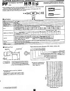
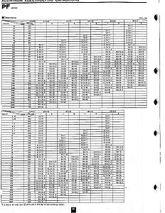
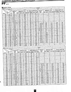
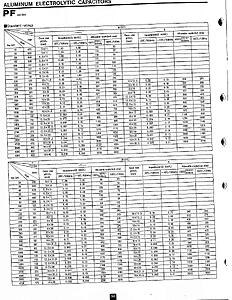
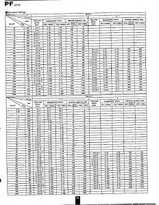
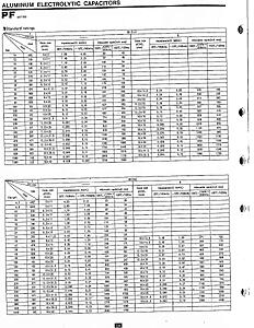
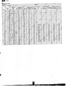
OK pardner! - I'll see your pretty pics bet, and raise you a complete set of specs for the original PF caps in our cars!


Last edited by LScowboyLS; 11-21-12 at 01:38 AM.
11-22-12, 08:44 AM
#146
Driver School Candidate

Join Date: Nov 2011
Location: Georgia
Posts: 11
Likes: 0
Received 0 Likes
on
0 Posts
Just some background as I have not driven my car for 6 months due to a drain on the battery after about 2 days of sitting. My 1993 LS400 with Traction has 182k plus miles. I paid $2000 and have had it for over a year. I ha;ve spent about $2000 on tires, complete tune up with OEM part (plugs, caps and rotors, wires, timing belt with tensioner, bench tested injectors with new orings, compression tested OK). All that helped a lot.
Even after all that work, it has always had a lack of power, with a very rich gas odor at the exhaust and white smoke after start-up that clears up in a few minutes.
The other day I charged it up and took it for a spin for about 5 miles. Ran good until I got near home and it started missing and bucking. Got home and it stalled, very rich exhaust and will now only start when I give it some throttle. It will run very rough, and idle about 200 RPM if it does not stall out. If I did not really like this car I would give up and sell it for parts. But it looks decent has driven great up till now. I stumbled across this post and will take the plunge and do the work on the ECU. I am an automation maintenance tech at KIA in Georgia, so I feel confident doing the work. Will post back when I get a chance to try the ECU fix. Thanks for the great post info here. Hope the advise here will resolve my problems with the battery draining and rough running condition,
11-23-12, 08:39 AM
#147
Lexus Champion
Thread Starter
I stumbled across this post and will take the plunge and do the work on the ECU. I am an automation maintenance tech at KIA in Georgia, so I feel confident doing the work. Will post back when I get a chance to try the ECU fix. Thanks for the great post info here. Hope the advise here will resolve my problems with the battery draining and rough running condition
Last edited by LScowboyLS; 07-20-13 at 02:58 AM.
11-23-12, 02:13 PM
#148
Driver School Candidate
Join Date: Nov 2011
Location: Georgia
Posts: 11
Likes: 0
Received 0 Likes
on
0 Posts
I have the ECU removed and there are problems. At least 2 caps (C103 + C105) leaked out and have apparent damage. I will order all the recommended caps from Digi-Key. Thanks for the info about low ESR caps from post #131. My 93 LS400 with Trac has the following electrolytic caps.
10uF-50V (C103 + C104)
100uF-10V (C105 + C108)
220uF-16V (C106)
15uF-35V (C831 + C832)
47uF-63V (C740)
A few pictures attached.
10uF-50V (C103 + C104)
100uF-10V (C105 + C108)
220uF-16V (C106)
15uF-35V (C831 + C832)
47uF-63V (C740)
A few pictures attached.
11-23-12, 05:45 PM
#149
Lexus Champion
Thread Starter
if you are careful and do a good job on this, following the tips I laid out throughout the thread, you are going to be amazed that this is going to make your LS400 run like it just rolled off the showroom floor!
PS - don't worry that some of the recommended caps are a higher voltage than what is original, that is even better! - it is just the capacitance value that must match.
double check the polarity markings of each cap (the + and - orientation of the cap in the board) before soldering in, and solder on both sides of the board and make sure no flecks of solder remain and bridge a trace - I inspect with a jeweler's loupe (magnifying glass) for quite a while when finished.
do your soldering quickly but thorough, caps don't like extended exposure to soldering iron heat, use at least a 40W iron and 63/37 leaded solder