Step-by-Step: Data System, Air Suspension Lowering System Install LS460 DIY How-To
 04-26-15, 10:51 PM
#1
Driver
Thread Starter

Well, this is my second new thread I'm posting on CL (Club Lexus) forums, and am proud to be able to contribute  ,
,
I’ve said this in the past, but gents like CJITTY, Tee, FreddyG, LexFather, Johnny and JoniNguyen have provided me the information, time and support, enabling me to tackle this fun little first project.
The basics:
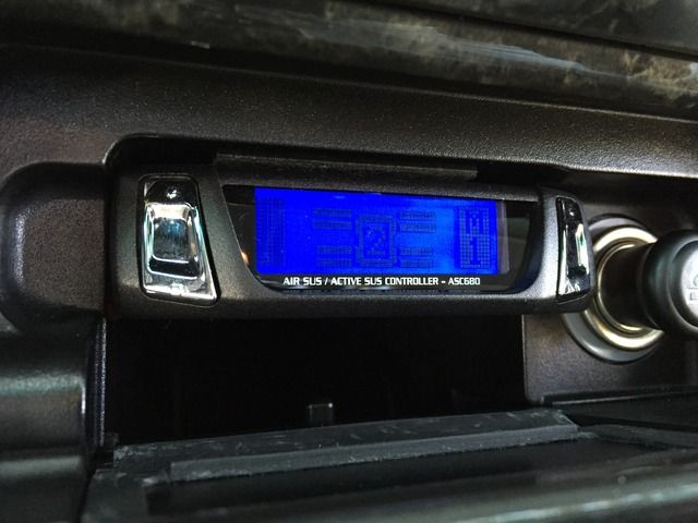
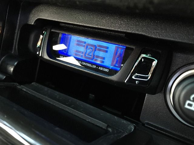
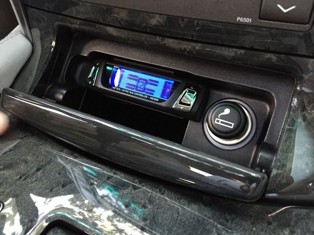
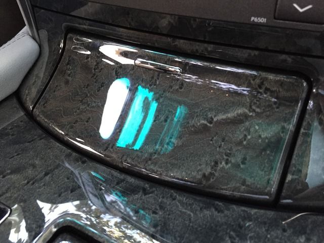
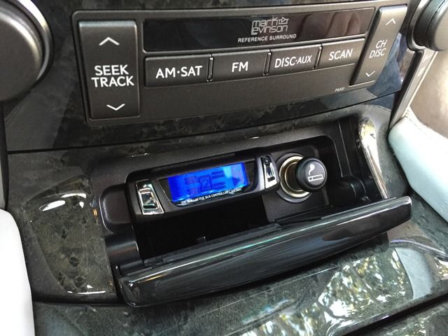
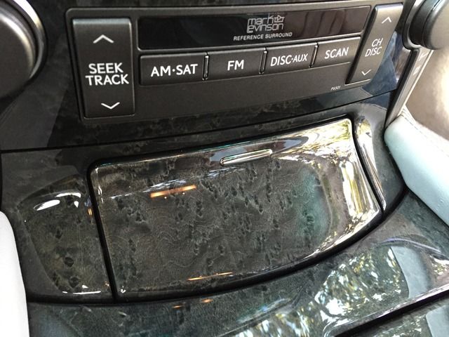
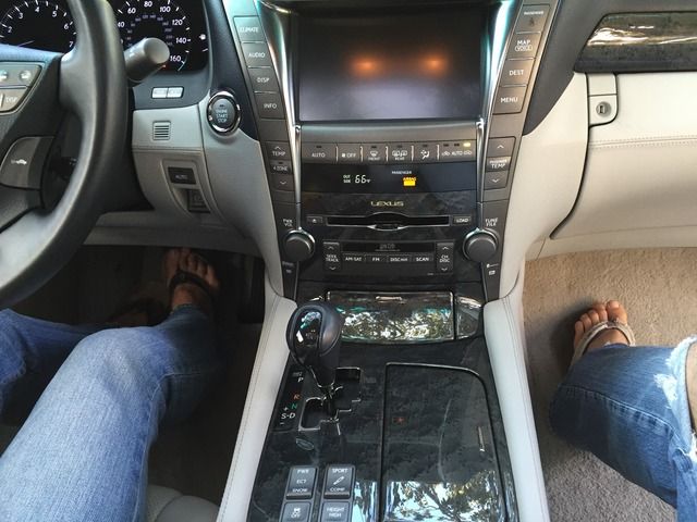
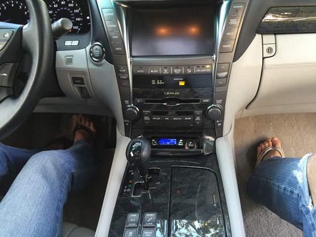
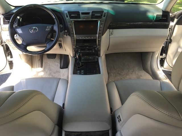
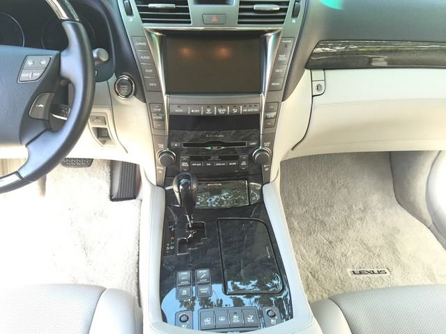
The Goal: To integrate the Data System control module into the ashtray location for…
.Here is the final product (8 summary pics). If these interest you and you’d like to know how this was completed, feel free to read the detailed descriptions and accompanying pics to help you out...
.
.
.
.
.
.
.
.
.
.
.
.
NOTE: I will slowly populate descriptions to the step-by-step pics below, time permitting. For now, I thought that my fellow CL users would still benefit from the pics even though I've yet to complete all of the supporting captions...
.
.
.
, I’ve said this in the past, but gents like CJITTY, Tee, FreddyG, LexFather, Johnny and JoniNguyen have provided me the information, time and support, enabling me to tackle this fun little first project.
The basics:
- 2007 LS460-L, Executive Package
- Data System, ASC680L controller
- Data System, H-087G wiring harness
The Goal: To integrate the Data System control module into the ashtray location for…
- Ease of use and daily access
- OEM/factory appearance and natural integration
- Secure and discrete mounting location
.Here is the final product (8 summary pics). If these interest you and you’d like to know how this was completed, feel free to read the detailed descriptions and accompanying pics to help you out...

.

.

.

.

.

.

.

.
.
.
.
.
NOTE: I will slowly populate descriptions to the step-by-step pics below, time permitting. For now, I thought that my fellow CL users would still benefit from the pics even though I've yet to complete all of the supporting captions...
.
.
.
Last edited by apaper; 05-09-15 at 01:46 PM.

The following users liked this post:
jzz30fan (07-16-18)
04-26-15, 10:53 PM
#2
Driver
Thread Starter
.
.
.
.
.
Well, here’s the start of my project…
.
.
.
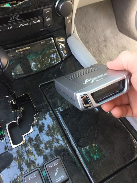
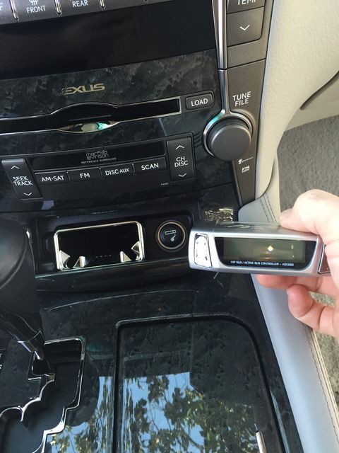
.The most challenging part of this installation was figuring out where to place this little silver box, what that would look like, and how that would ultimately be achieved…
.
.
.After much consideration and mocking up various places in the car to mount the Data System control module interface/housing (which we’ll name ‘controller’ herein), it was clear to me that the most logical place would ultimately be the factor ashtray location…
.
.
.
.
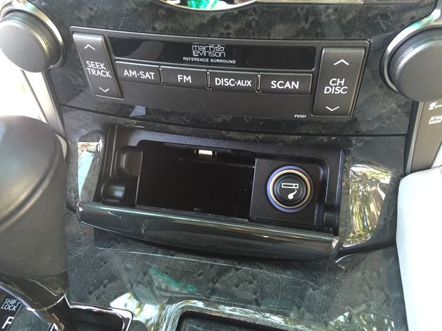
.The concept of squeezing the controller into the ashtray posed a bit of a challenge. As you can see, it’s bigger than the removable ashtray insert…
.
.
.
.
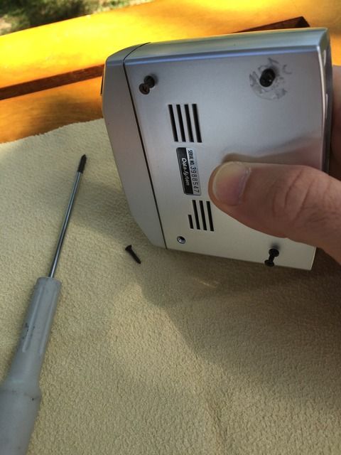
.So in order to know what I was dealing with, the first step was to start tearing things apart. How else would I know how to graft the controller into the ashtray!?!?...
.
.
.
.
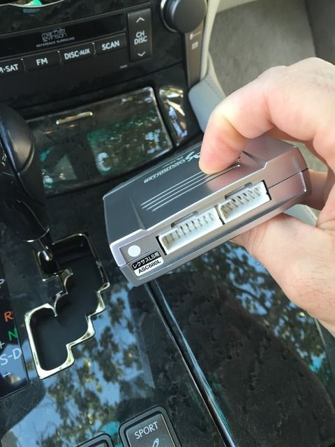
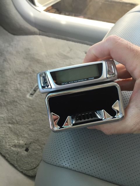
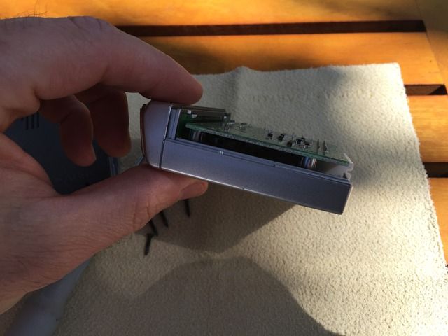
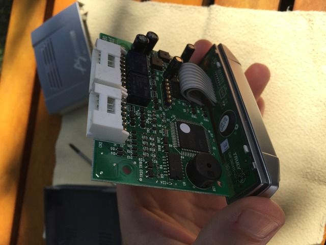
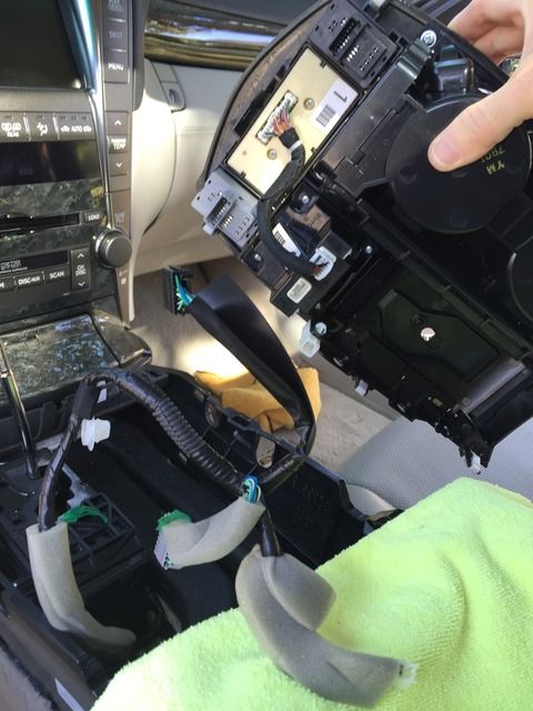
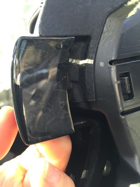
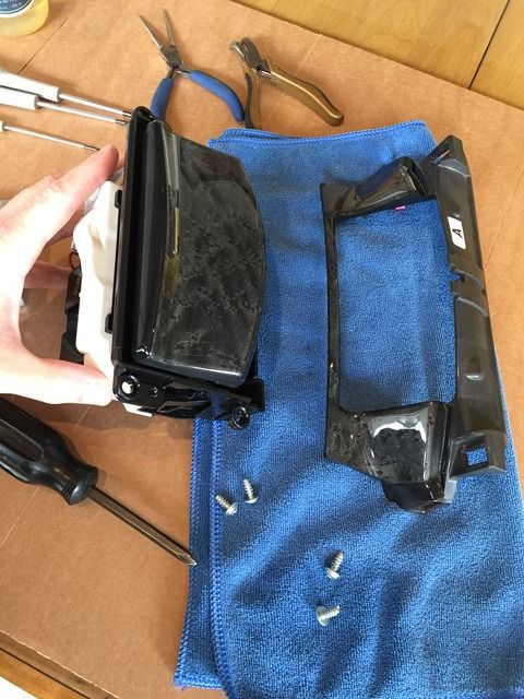
.You’ll notice how the top portion of the plastic cover/housing “slides” up and off, releasing the front plastic fascia (the portion where you press the buttons). This provides stability for the fascia and prevents it from flexing back and forth…
.
.
.You can see the locking grooves around the fascia between my fingers…
.
.
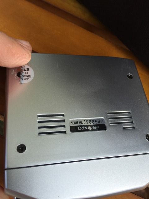
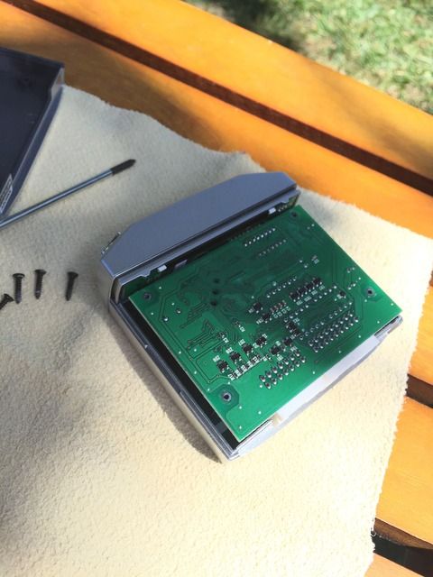
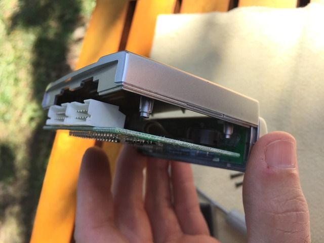
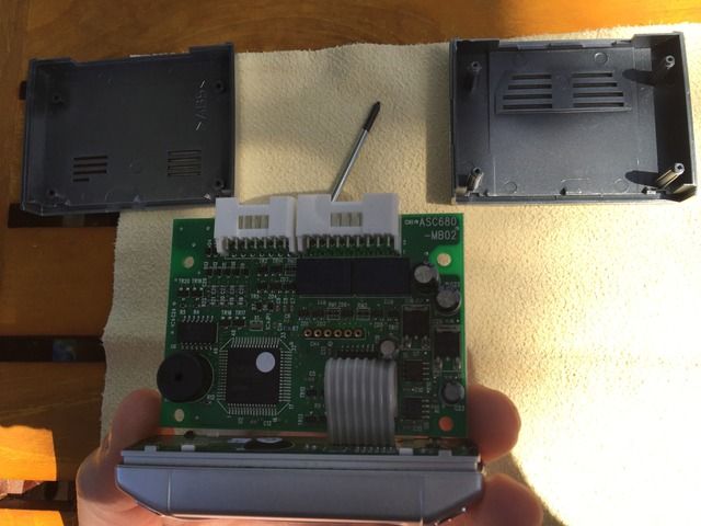
.An exploded view of the PCB (Printed Circuit Board) and the top/bottom housing covers…
.
.
.While contemplating how to proceed, I thought I would begin to dismantle the vehicle in preparation of the harness installation and controller’s wiring.
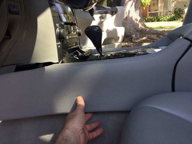
I started by disassembling both upholstered side panels around the center console; the driver’s side first (but either is fine). You’ll notice there are 7 clips on each panel (despite 8 being present on both panels-one of which is not used). Begin the panel removal by pulling on the side furthest forward (by the foot wells). Once those clips release, move your way towards the back of the car. CAREFUL: the rear-most clips are beveled into the console. Look closely, and you’ll see that the don’t pull out, but rather move forward.
.
.
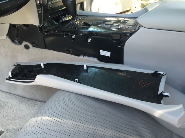
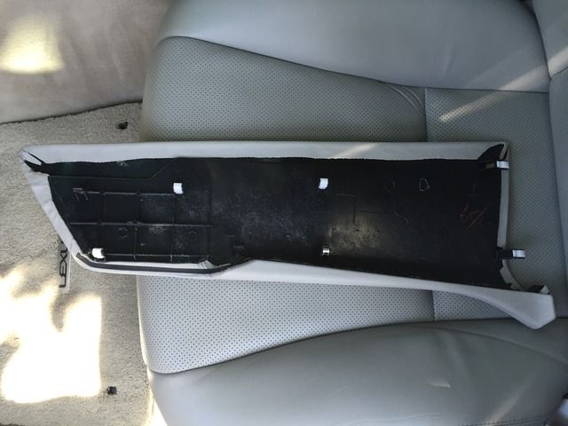
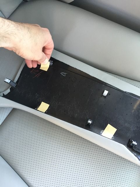
.A pic of the driver’s side panel removed, and folded downward to show alignment of the male/female portions…
.
.
.Another pic-driver’s side panel removed…
.
.
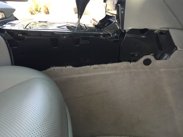
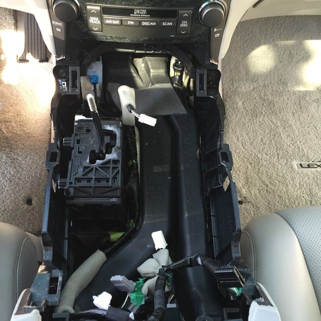
.The driver’s side console fully exposed. Notice the female portions for the clips. You’ll also notice 2 phillips/nuts (10mm). These will release the entire center console later…
.
.
.One of the clips fell off during the removal process…
.
.
.
.Grabbing a pair of needle nose pliers and a magnet helped me to retrieve the clip…
.
.
.Now it’s time to repeat the process for the Passenger side of the car…
.
.
.
.
.
.
.
.
.
.
Well, here’s the start of my project…
.

.
.
.The most challenging part of this installation was figuring out where to place this little silver box, what that would look like, and how that would ultimately be achieved…

.
.
.After much consideration and mocking up various places in the car to mount the Data System control module interface/housing (which we’ll name ‘controller’ herein), it was clear to me that the most logical place would ultimately be the factor ashtray location…

.

.

.
.
.The concept of squeezing the controller into the ashtray posed a bit of a challenge. As you can see, it’s bigger than the removable ashtray insert…

.

.

.
.
.So in order to know what I was dealing with, the first step was to start tearing things apart. How else would I know how to graft the controller into the ashtray!?!?...

.

.

.
.
.You’ll notice how the top portion of the plastic cover/housing “slides” up and off, releasing the front plastic fascia (the portion where you press the buttons). This provides stability for the fascia and prevents it from flexing back and forth…

.
.
.You can see the locking grooves around the fascia between my fingers…

.
.
.An exploded view of the PCB (Printed Circuit Board) and the top/bottom housing covers…

.
.
.While contemplating how to proceed, I thought I would begin to dismantle the vehicle in preparation of the harness installation and controller’s wiring.
I started by disassembling both upholstered side panels around the center console; the driver’s side first (but either is fine). You’ll notice there are 7 clips on each panel (despite 8 being present on both panels-one of which is not used). Begin the panel removal by pulling on the side furthest forward (by the foot wells). Once those clips release, move your way towards the back of the car. CAREFUL: the rear-most clips are beveled into the console. Look closely, and you’ll see that the don’t pull out, but rather move forward.

.
.
.A pic of the driver’s side panel removed, and folded downward to show alignment of the male/female portions…

.
.
.Another pic-driver’s side panel removed…

.
.
.The driver’s side console fully exposed. Notice the female portions for the clips. You’ll also notice 2 phillips/nuts (10mm). These will release the entire center console later…

.
.
.One of the clips fell off during the removal process…

.

.
.
.Grabbing a pair of needle nose pliers and a magnet helped me to retrieve the clip…

.
.
.Now it’s time to repeat the process for the Passenger side of the car…

.

.

.

.
.
.
Last edited by apaper; 05-09-15 at 06:02 PM.
04-26-15, 10:54 PM
#3
Driver
Thread Starter
Pics 26+...
.
.
.
.I noticed there were some plastic adhesive tabs that had not been removed from the factory when originally sold. I’m thinking these held the plastic covering in place while the car was being delivered to its original owner…
.
.
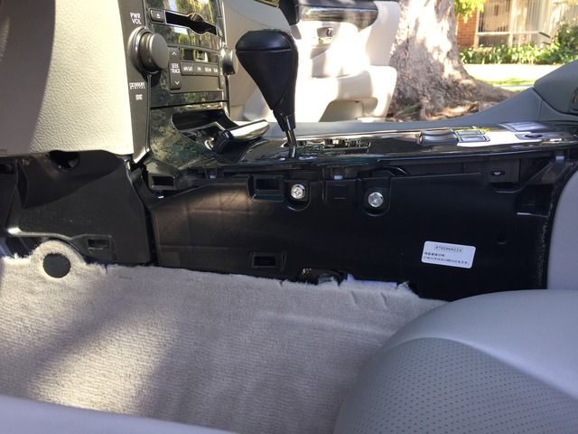
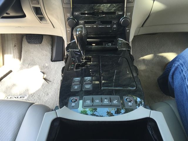
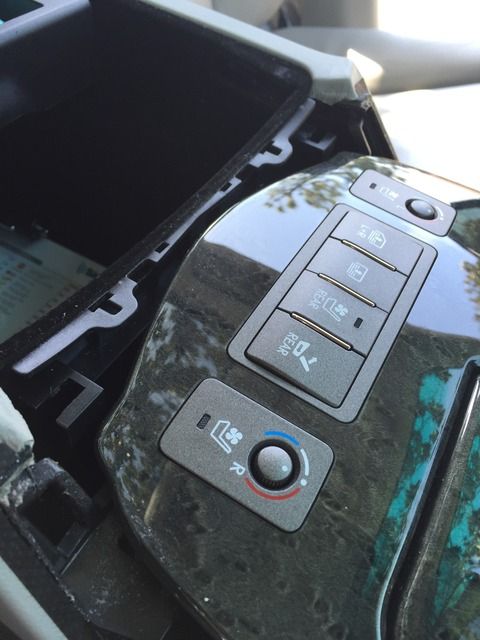
.An image of the center console with the sides removed. Now we’ll need to release the next piece of the puzzle…
.
.
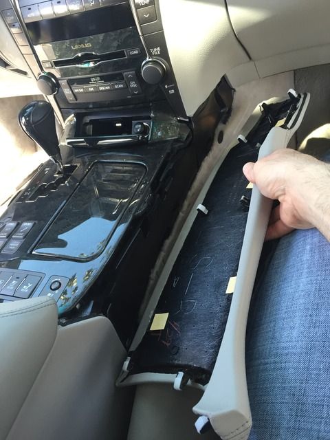
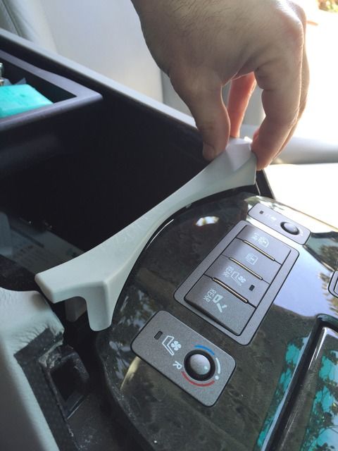
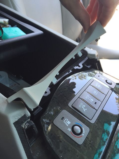
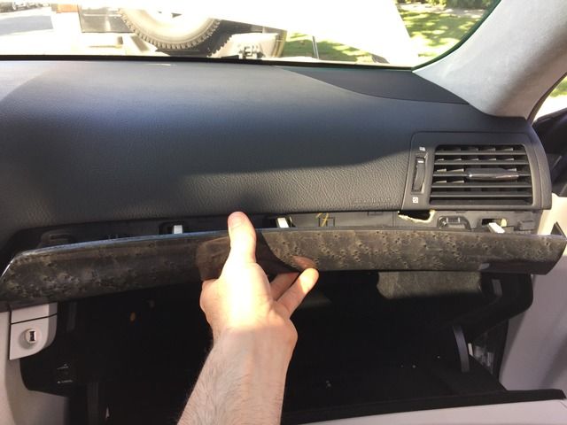
.Grab the plastic trim (as shown) and pull directly upward. I avoided using any sharp objects for prying purposes and relegated the hard work to my fingers. Just work the plastic panel on each side pulling firmly upward. You’ll begin to see it move…
.
.
.
.
.
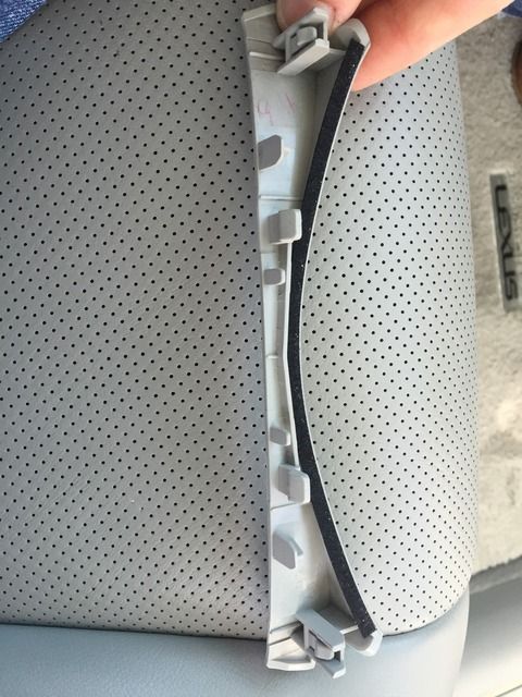
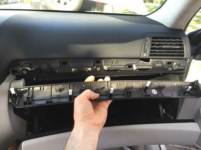
.The panel removed and flipped upside down…
.
.
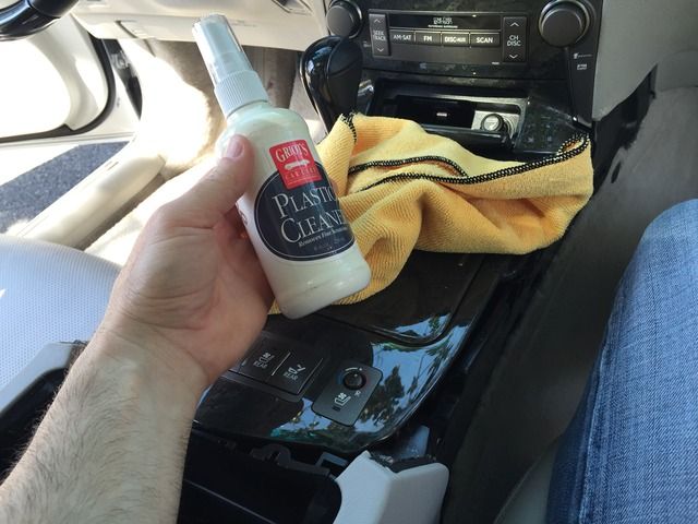
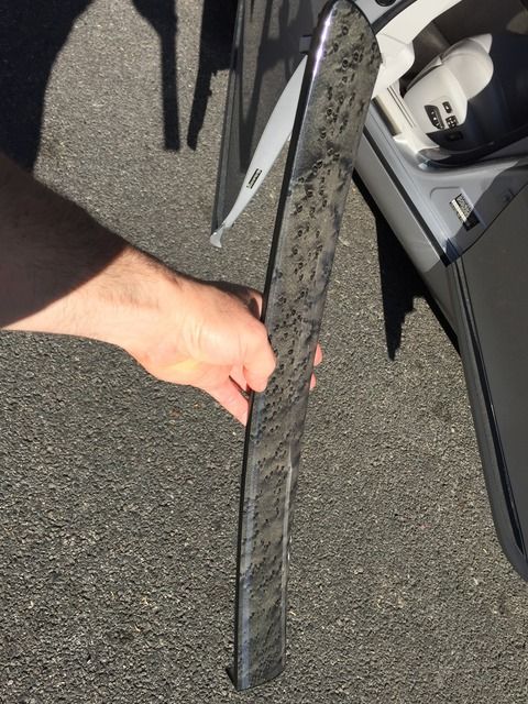
.I thought this was as a good a time as any to take time to clean the wood with my cleaner. There was a little grit built up around the edges over the years…
.
.
.Now back to releasing the top of the center console. Take your #3 (very large) phillips screwdriver or 10mm socket to release the 2 machine bolts on the Driver’s side of the top of the console…
.
.
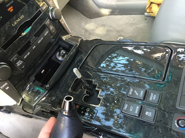
.Then turn the car ON. Place the car’s Parking Brake ON…
.
.
. Place the car IN gear. Moving the gear lever into Neutral allows for an easier removal/lifting of the top of the center console. This is also needed to aid in the future removal of the ashtray assembly…
.
.
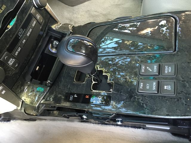
.Unscrew the gearshift **** which will allow the top of the console to be lifted up and off…
.
.
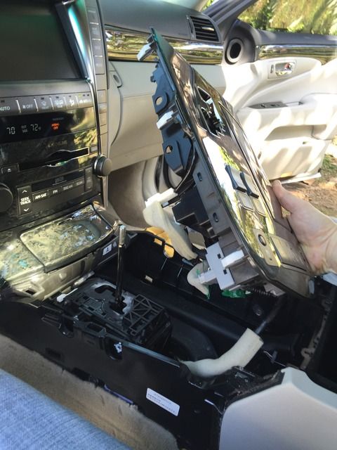
.Take a very large screwdriver (or plastic panel remover tool) and carefully pry the top of the console up, aiding in lifting and separating the 6 very large/strong clips holding the top of the console in place…
.
.
.Carefully remove the top of the center console, pulling up, but note that the wiring harnesses will be limiting your mobility…
.
.
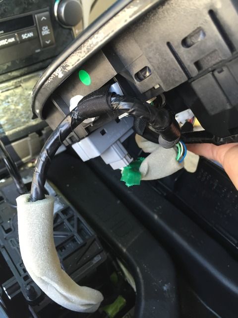
.Remove 3 Molex plugs (wiring harnesses) and 1 harness retaining clip (which keeps the wiring harness organized and out of the way) to fully remove/detach the top of the console…
.
.
.
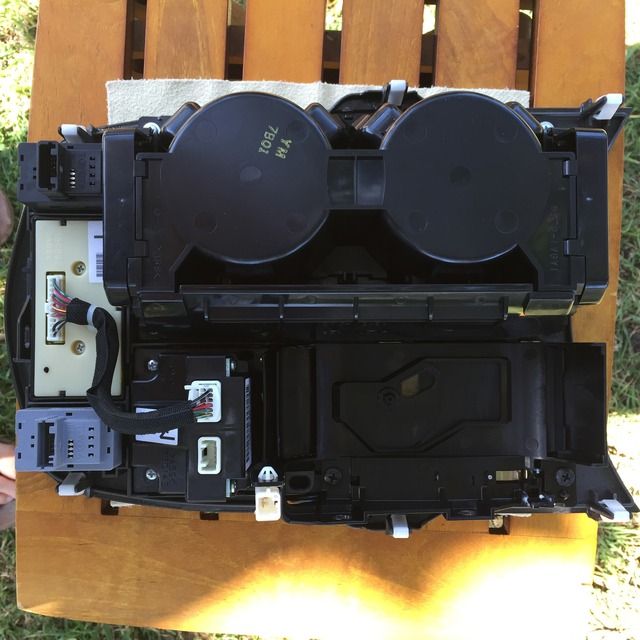
.This is an image of the bottom side of the center console. This gives you perspective of what’s what…
.
.
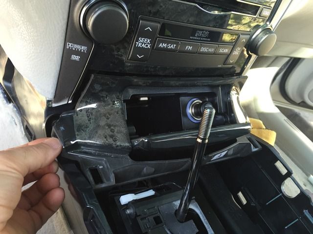
.Get your fingers ready! This will require some strength (should you not use a pry device). I used my fingers to pull out (directly towards the direction of the sunroof) the ashtray which is held into place with 2 strong clips (as found on the top of the center console)...
.
.
.
.Notice the female receptacles for the ashtray’s clips are angled at 45 degrees. You’ll want to pull up and directly perpendicular from this surface (thus, towards the direction of the sunroof)…
.
.
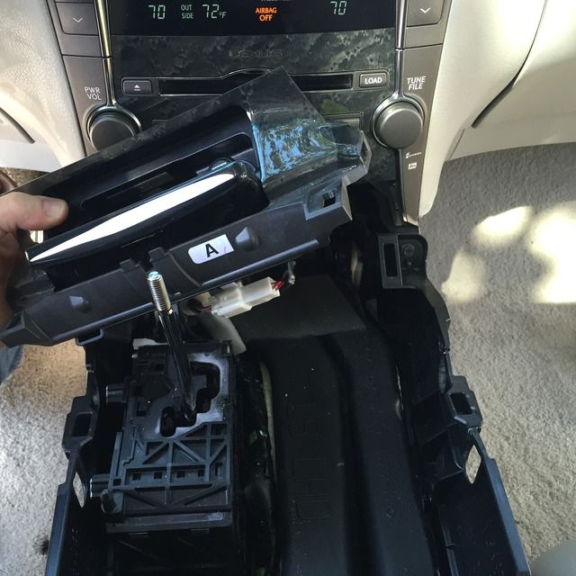
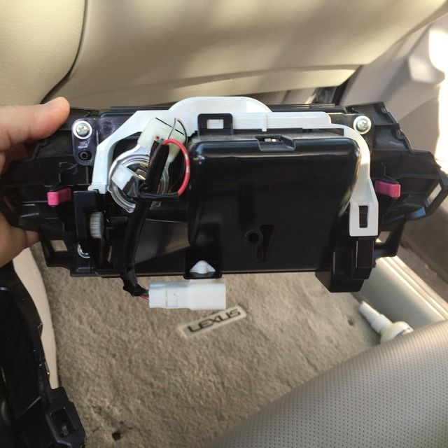
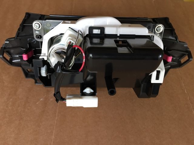
.You can see the backside of the ashtray assembly. The 2 clasps that hold the assembly firmly in place are 2 red clips. This is what the back of the ashtray looks like before a bit of cutting and drilling…
.
.
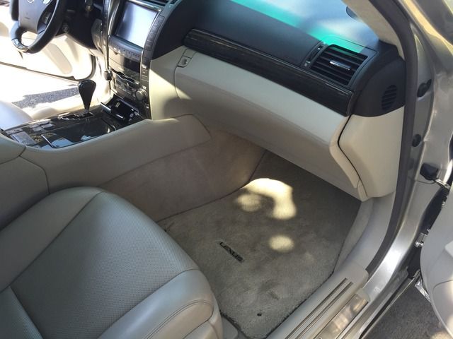
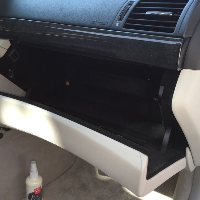
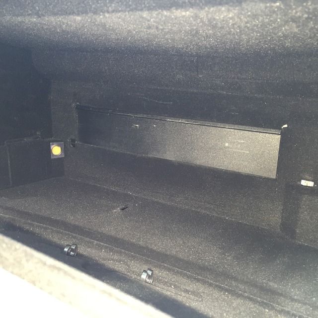
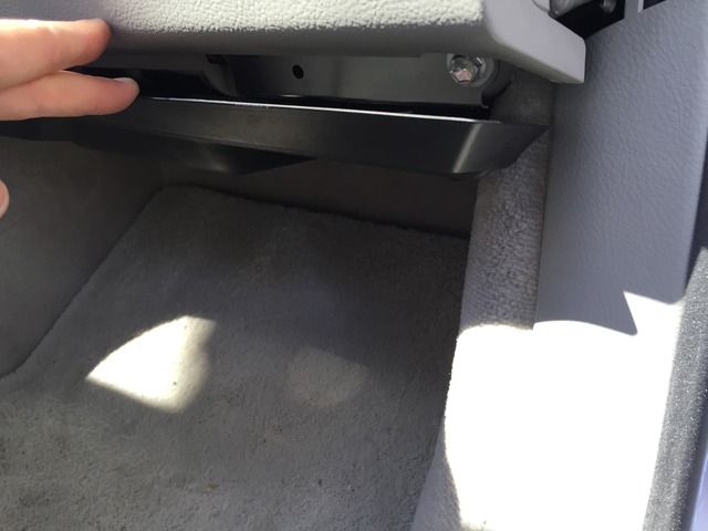
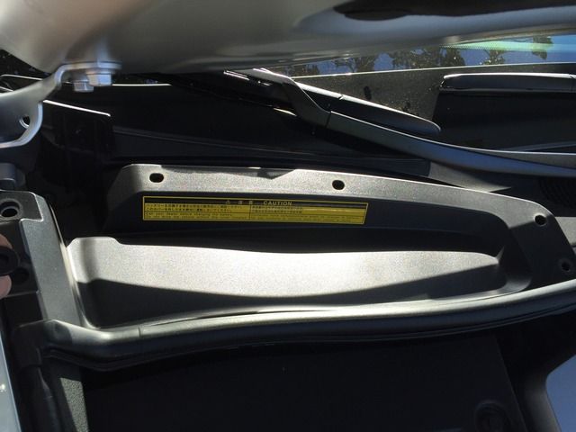
.Now it’s time to remove the glovebox. Start by removing the center shelf. It merely slides up and out. By removing the box, you’ll gain access to the car’s Air-Suspension ECU/ECM (Electronic Control Unit/Module, or computer)…
.
.
.Up close image of the glovebox shelf removed…
.
.
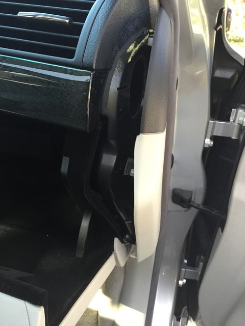
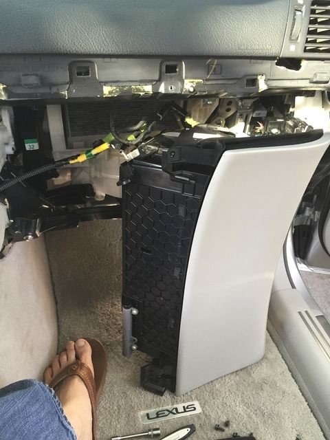
.Begin to remove the side cap/cover of the passenger side dash…
.
.
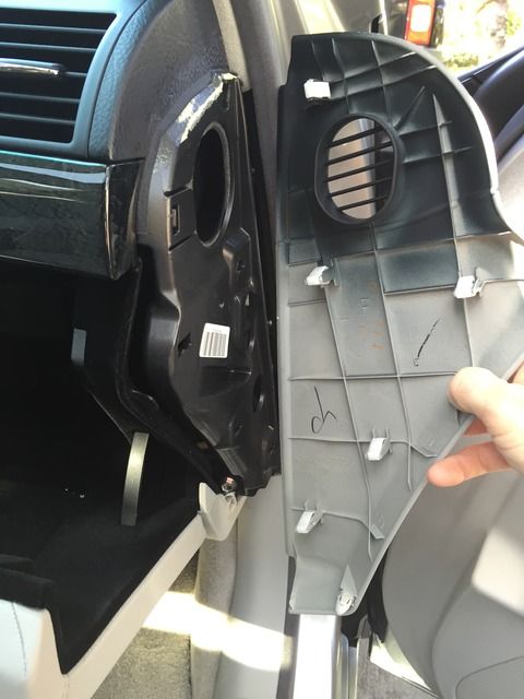
.Notice the 6 clips that hold the cap/cover in place…
.
.
.
.
.
.
.I noticed there were some plastic adhesive tabs that had not been removed from the factory when originally sold. I’m thinking these held the plastic covering in place while the car was being delivered to its original owner…

.
.
.An image of the center console with the sides removed. Now we’ll need to release the next piece of the puzzle…

.
.
.Grab the plastic trim (as shown) and pull directly upward. I avoided using any sharp objects for prying purposes and relegated the hard work to my fingers. Just work the plastic panel on each side pulling firmly upward. You’ll begin to see it move…

.

.

.

.
.
.The panel removed and flipped upside down…

.
.
.I thought this was as a good a time as any to take time to clean the wood with my cleaner. There was a little grit built up around the edges over the years…

.
.
.Now back to releasing the top of the center console. Take your #3 (very large) phillips screwdriver or 10mm socket to release the 2 machine bolts on the Driver’s side of the top of the console…

.
.
.Then turn the car ON. Place the car’s Parking Brake ON…

.
.
. Place the car IN gear. Moving the gear lever into Neutral allows for an easier removal/lifting of the top of the center console. This is also needed to aid in the future removal of the ashtray assembly…

.
.
.Unscrew the gearshift **** which will allow the top of the console to be lifted up and off…

.
.
.Take a very large screwdriver (or plastic panel remover tool) and carefully pry the top of the console up, aiding in lifting and separating the 6 very large/strong clips holding the top of the console in place…

.
.
.Carefully remove the top of the center console, pulling up, but note that the wiring harnesses will be limiting your mobility…

.
.
.Remove 3 Molex plugs (wiring harnesses) and 1 harness retaining clip (which keeps the wiring harness organized and out of the way) to fully remove/detach the top of the console…

.

.
.
.This is an image of the bottom side of the center console. This gives you perspective of what’s what…

.
.
.Get your fingers ready! This will require some strength (should you not use a pry device). I used my fingers to pull out (directly towards the direction of the sunroof) the ashtray which is held into place with 2 strong clips (as found on the top of the center console)...

.

.
.
.Notice the female receptacles for the ashtray’s clips are angled at 45 degrees. You’ll want to pull up and directly perpendicular from this surface (thus, towards the direction of the sunroof)…

.
.
.You can see the backside of the ashtray assembly. The 2 clasps that hold the assembly firmly in place are 2 red clips. This is what the back of the ashtray looks like before a bit of cutting and drilling…

.
.
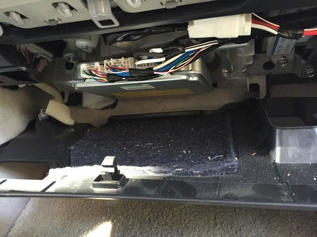
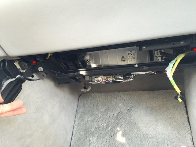
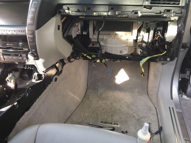
.Now it’s time to remove the glovebox. Start by removing the center shelf. It merely slides up and out. By removing the box, you’ll gain access to the car’s Air-Suspension ECU/ECM (Electronic Control Unit/Module, or computer)…

.
.
.Up close image of the glovebox shelf removed…

.
.
.Begin to remove the side cap/cover of the passenger side dash…

.
.
.Notice the 6 clips that hold the cap/cover in place…

.
.
.
Last edited by apaper; 05-30-15 at 01:38 PM.
04-26-15, 10:54 PM
#4
Driver
Thread Starter
Pics 51+...
.
.
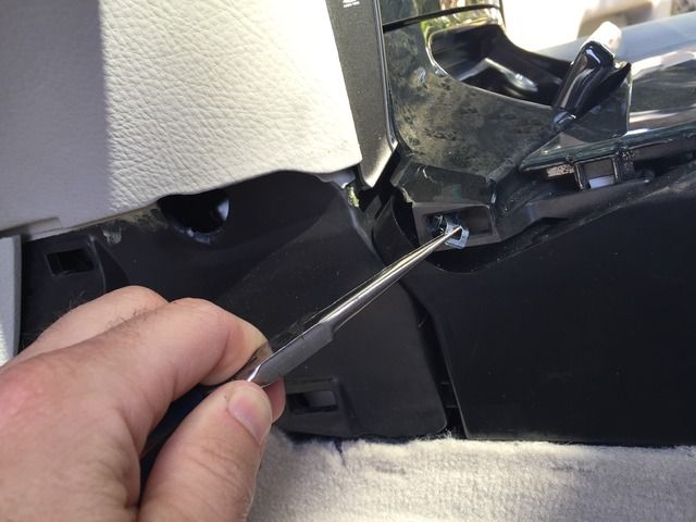
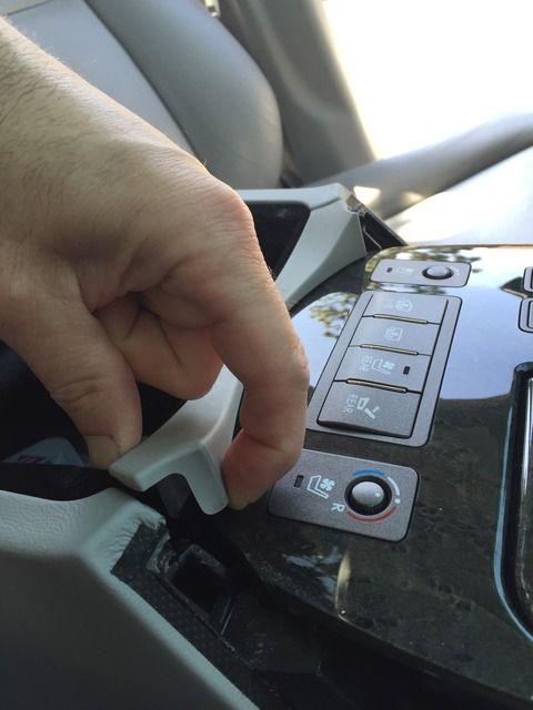
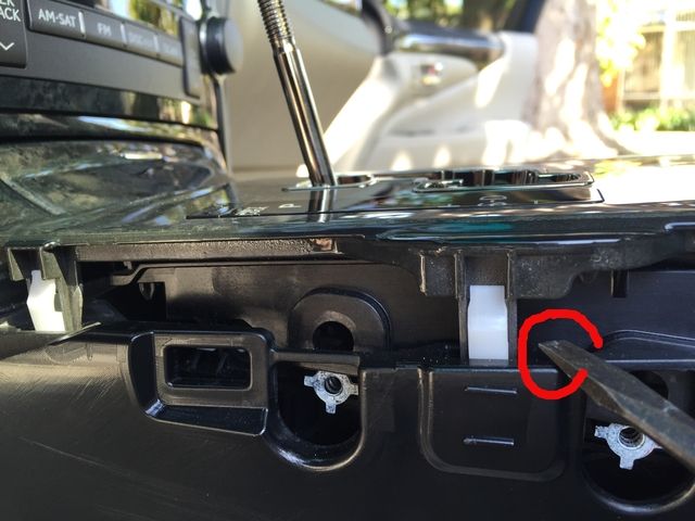
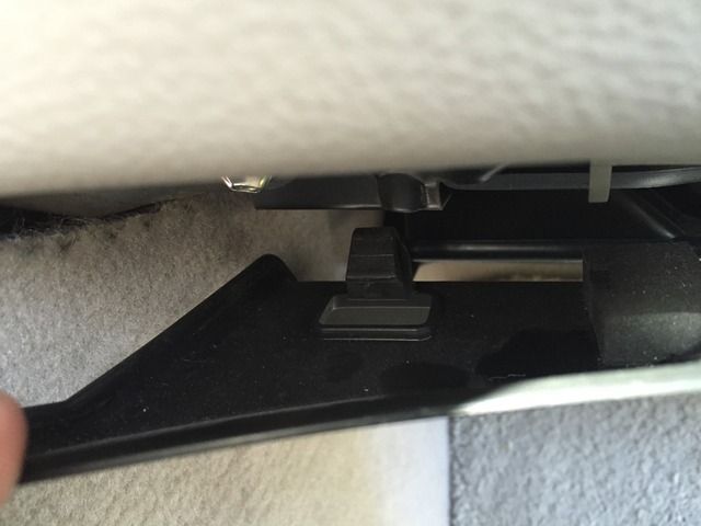
.You’ll notice that when pulling on the black under-dash covering, it will only bend down so much. In order to release this black plastic cover, you’ll need to locate the ‘release tabs’. There are 4 of these across the front edge of the cover…
.
.
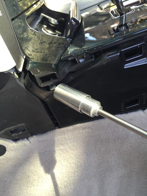
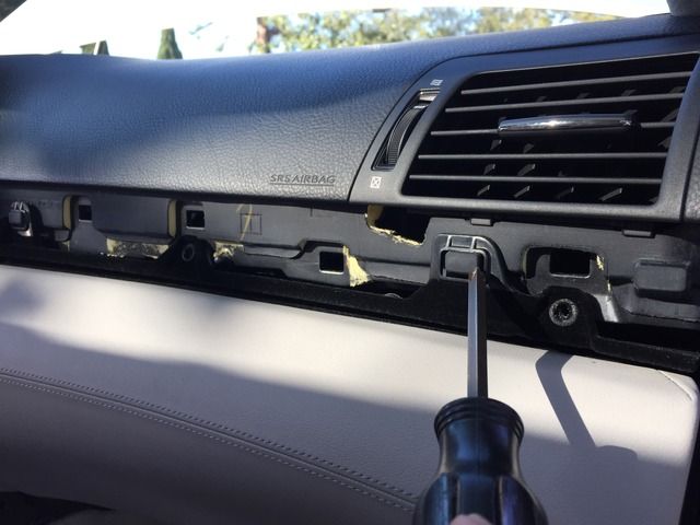
.Take a flat head screwdriver and ‘push’ the clip towards the front of the car. This compresses the clip. While doing such, pull down on the plastic cover creating tension on the clip. Once the clip is released, it will ‘pop’ out of its socket. Repeat 3 more times…
.
.
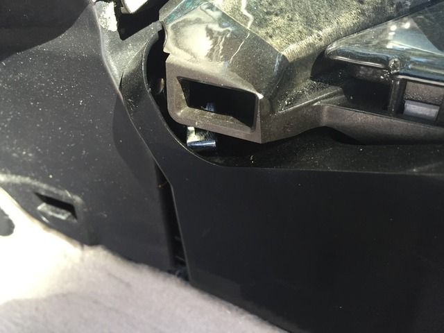
.Up close image of the clips holding in the front of the cover…
.
.
.
.
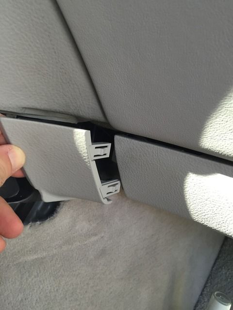
.Notice the edge of the black cover closest to the front of the car has 2 male protrusions—theses are the 2 places that ‘anchor’ into the footwell area, allowing the cover to stay up…
.
.
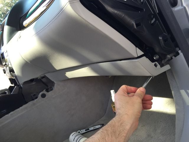
.IMPORTANT1: Do NOT pull the plastic knee bolster (which says ‘SRS Knee Airbag’) away from the dash. Said plastic panel does NOT pull off (or detach, as it would appear) from the lower dash. You MUST unbolt the SRS Knee Airbag by the 2 outside 10mm bolts.
.IMPORTANT2: The 3rd 10mm bolt is HIDDEN. See next pics…
.
.
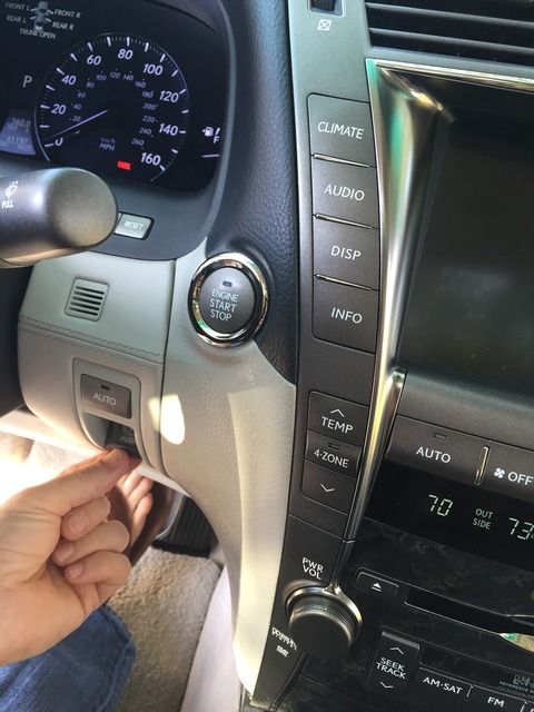
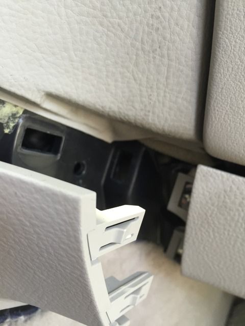
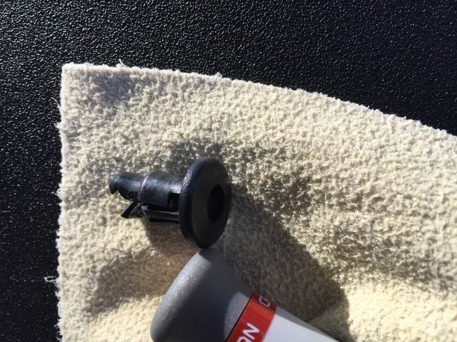
.Take the small plastic cap (which is located in between the SRS Knee Airbag and the side of the passenger center console) and pull it straight back towards the rear of the car, keeping the direction parallel to the floor. Careful to not bend/pry/break the plastic tabs…
.
.
.
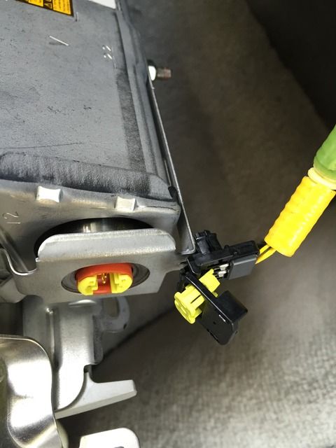
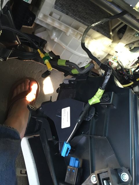
.Once the 3-10mm bolts have been removed, the entire SRS Knee Airbag will drop down. Careful of its weight and the fact it is attached to a wiring umbilical. My wiring umbilical wasn’t long enough to rest the airbag onto the footwell. Thus, I had to prop it up while readying to remove the molex plug...
.
.
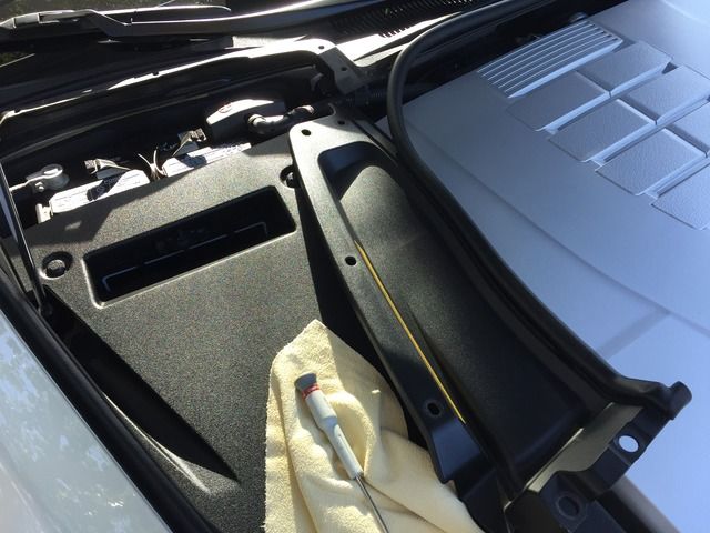
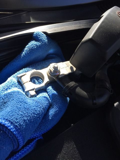
.IMPORTANT: Before removing the SRS Airbag ‘molex plug’ (yellow harness), I recommend disconnecting BOTH sides of the car’s battery. This said, you’ll want to remove battery trim plastic in the engine compartment…
.
.
.The small black plastic fasteners can be easily removed by taking a small pointy object (like a small Philips screwdriver) and pushing the ‘center pin’ down/in, so that the plastic fastener ‘releases’ its outer teeth…
.
.
.
.
.
.
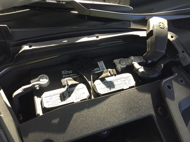
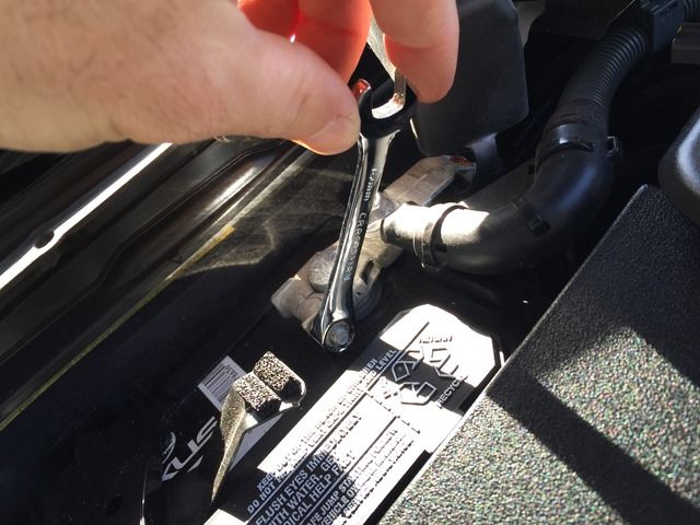
.FIRST: Begin by DISCONNECTING the POS (positive ‘+’) side of the battery terminal. It is important to NOT start with the ground as this instigates other electronic devices in the car to act as the ground for the vehicle which can have and adverse affect (in theory) on devices that might pass too much current via their respective grounds.
.CAREFUL: Do NOT allow the POS terminal to touch ANY metal of the vehicle-NOT even the battery hold-downs.
.SECOND: Disconnect the NEG (neg ‘-‘) side of the battery terminal…
.
.
.NOTE: I used cloths to isolate each battery terminal, ensuring safety from any possible connection points…
.
.
.Now remove the SRS Airbag Molex plug. Simply get a small flat-head screwdriver and ‘pop’ the yellow insert OUT of the plug. This will then allow the top of the clip to fold open. Once hinged open, simply give the molex plug a firm tug straight out…
.
.
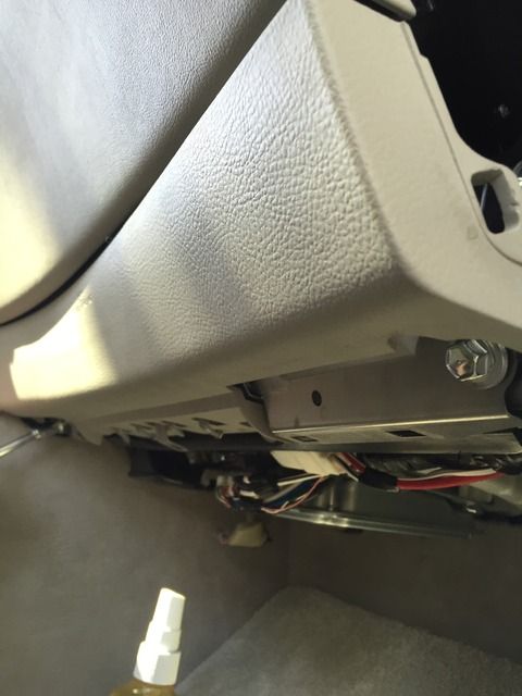
.Remove the 2 bottom screws to the glovebox. There are 3 more up above which we’ll get to…
.
.
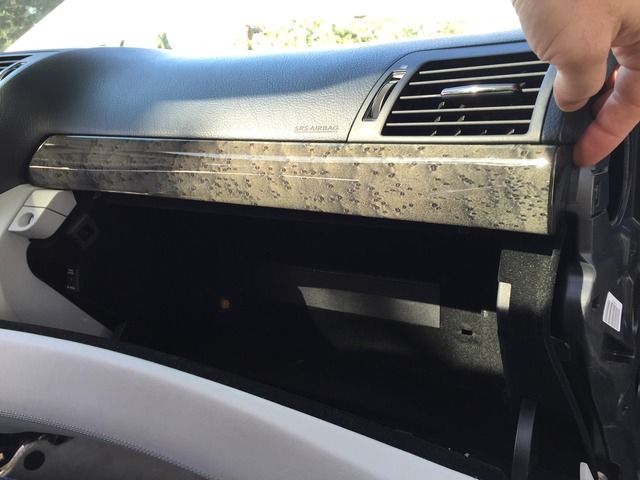
.Remove the upper wooden trim from above the glovebox. This exposes the upper 3 screws which you will need access to…
.
.
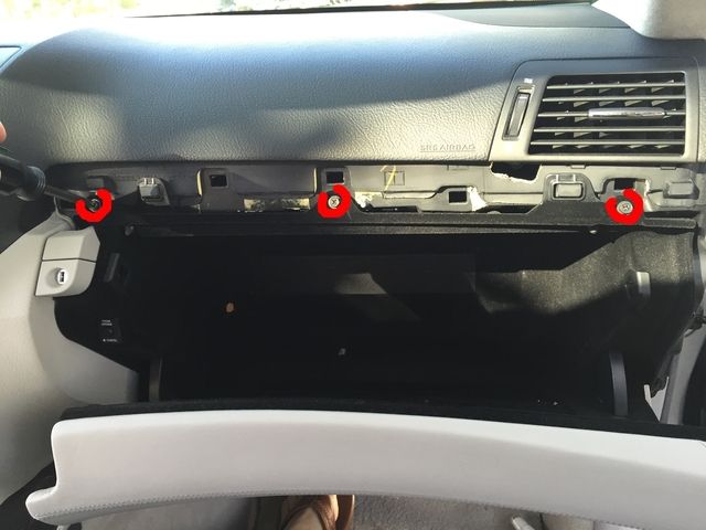
.CAREFUL: Now carefully and slowly pull (prying NOT needed with any tools, which MAY DAMAGE the edges of your dash and wood trim) the wood trim straight back towards the rear of the car, keeping the angle parallel with the floor. Work your way from the far right (passenger’s side) towards the center of the car…
.
.
.Five (5) strong clips are holding this trim into place…
.
.
.
.
.
.You’ll notice that when pulling on the black under-dash covering, it will only bend down so much. In order to release this black plastic cover, you’ll need to locate the ‘release tabs’. There are 4 of these across the front edge of the cover…

.
.
.Take a flat head screwdriver and ‘push’ the clip towards the front of the car. This compresses the clip. While doing such, pull down on the plastic cover creating tension on the clip. Once the clip is released, it will ‘pop’ out of its socket. Repeat 3 more times…

.
.
.Up close image of the clips holding in the front of the cover…

.

.

.
.
.Notice the edge of the black cover closest to the front of the car has 2 male protrusions—theses are the 2 places that ‘anchor’ into the footwell area, allowing the cover to stay up…

.
.
.IMPORTANT1: Do NOT pull the plastic knee bolster (which says ‘SRS Knee Airbag’) away from the dash. Said plastic panel does NOT pull off (or detach, as it would appear) from the lower dash. You MUST unbolt the SRS Knee Airbag by the 2 outside 10mm bolts.
.IMPORTANT2: The 3rd 10mm bolt is HIDDEN. See next pics…


.
.
.Take the small plastic cap (which is located in between the SRS Knee Airbag and the side of the passenger center console) and pull it straight back towards the rear of the car, keeping the direction parallel to the floor. Careful to not bend/pry/break the plastic tabs…

.

.
.
.Once the 3-10mm bolts have been removed, the entire SRS Knee Airbag will drop down. Careful of its weight and the fact it is attached to a wiring umbilical. My wiring umbilical wasn’t long enough to rest the airbag onto the footwell. Thus, I had to prop it up while readying to remove the molex plug...

.
.
.IMPORTANT: Before removing the SRS Airbag ‘molex plug’ (yellow harness), I recommend disconnecting BOTH sides of the car’s battery. This said, you’ll want to remove battery trim plastic in the engine compartment…

.
.
.The small black plastic fasteners can be easily removed by taking a small pointy object (like a small Philips screwdriver) and pushing the ‘center pin’ down/in, so that the plastic fastener ‘releases’ its outer teeth…

.

.

.

.

.
.
.FIRST: Begin by DISCONNECTING the POS (positive ‘+’) side of the battery terminal. It is important to NOT start with the ground as this instigates other electronic devices in the car to act as the ground for the vehicle which can have and adverse affect (in theory) on devices that might pass too much current via their respective grounds.
.CAREFUL: Do NOT allow the POS terminal to touch ANY metal of the vehicle-NOT even the battery hold-downs.
.SECOND: Disconnect the NEG (neg ‘-‘) side of the battery terminal…

.
.
.NOTE: I used cloths to isolate each battery terminal, ensuring safety from any possible connection points…

.
.
.Now remove the SRS Airbag Molex plug. Simply get a small flat-head screwdriver and ‘pop’ the yellow insert OUT of the plug. This will then allow the top of the clip to fold open. Once hinged open, simply give the molex plug a firm tug straight out…

.
.
.Remove the 2 bottom screws to the glovebox. There are 3 more up above which we’ll get to…

.
.
.Remove the upper wooden trim from above the glovebox. This exposes the upper 3 screws which you will need access to…

.
.
.CAREFUL: Now carefully and slowly pull (prying NOT needed with any tools, which MAY DAMAGE the edges of your dash and wood trim) the wood trim straight back towards the rear of the car, keeping the angle parallel with the floor. Work your way from the far right (passenger’s side) towards the center of the car…

.
.
.Five (5) strong clips are holding this trim into place…

.
.
.
Last edited by apaper; 05-30-15 at 01:38 PM.
04-26-15, 10:55 PM
#5
Driver
Thread Starter
Pics 76+…
.
.
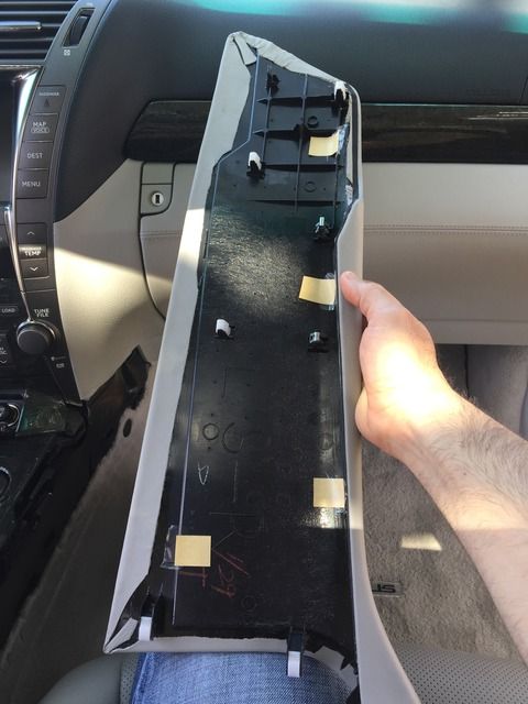
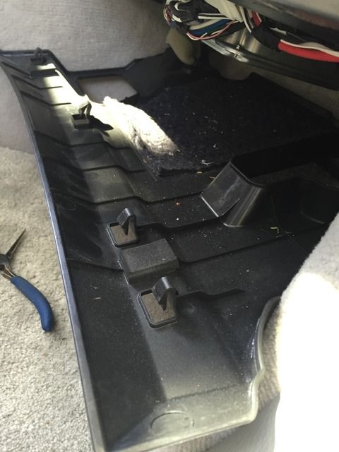
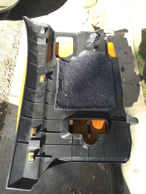
.Notice the 5 clips on the backside of the panel and where they’re located…
.
.
.
.
.
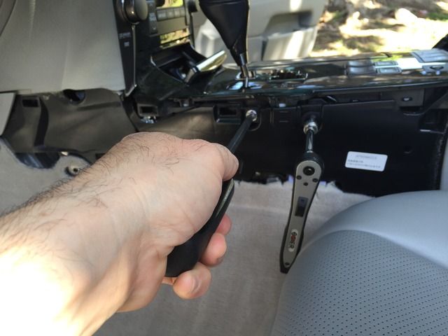
.Remove the three (3) phillips screws at the top and two from the bottom of the glovebox…
.
.
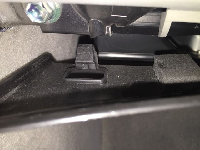
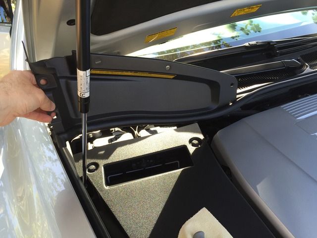
.These two (2) rubber rectangular nodules (pointed out by my screwdriver) will prevent the glovebox from falling down once you’ve removed the 3 screws…
.
.
.The glovebox has 2 (black & blue) molex plugs (for interior light and footwell light) you’ll need to unplug in order to fully remove…
.
.
.I found it easier to place the glovebox onto its side. I could then work around things a bit easier prior to fully removing the glovebox…
.
.
.And the glovebox fully removed…
.
.
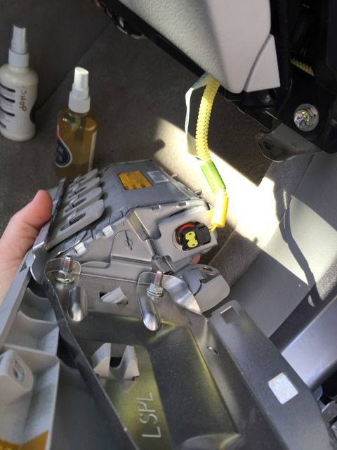
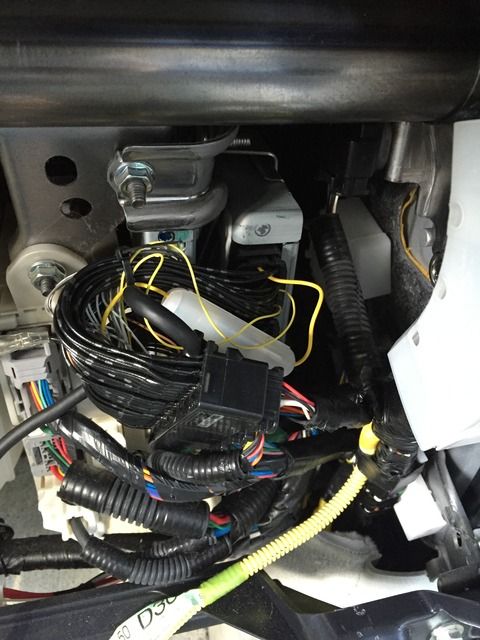
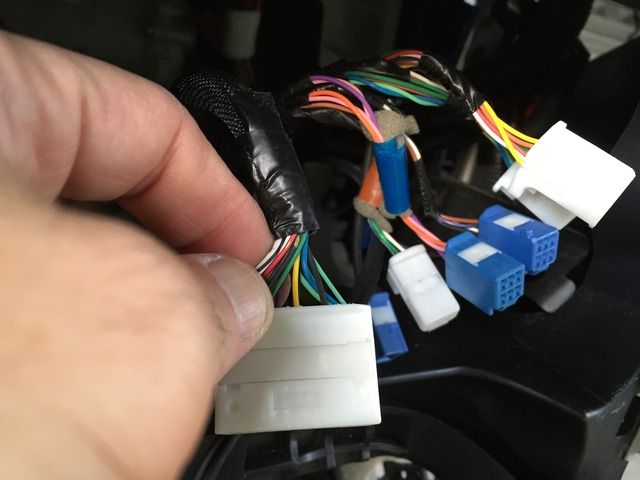
.Now you’ll want to do the following THREE STEPS:
1st. Locate and Remove the (3) OEM (factory) black molex plugs/connectors from the OEM Lowering Module (as circled and pointed to with my needle nose pliers)…
2nd. Plug the Datasystem’s (3) INDVIDUAL molex plugs (1 white, 2 black) into the OEM Lowering Module…
3rd. Plug the loose (3) OEM black molex plugs into the SINGLE LONG black Datasystem female molex receptacle…
.
.
.IMPORTANT: The wires will be very tight. Take you time to manipulate the bends. Ensure the molex plugs are properly seated/locked. Don’t force anything. Just continue to move and massage the wires around until things fit. Patience is your friend here…
.
.
.I decided to coil up some excess Datasystem wiring/umbilical here behind the glovebox. I wanted to avoid having too much extra length at the control module side (near the ashtray)…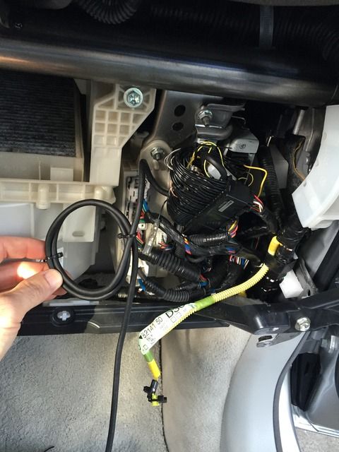
.
.
.Then run the umbilical up along the center console. I chose to run the wire INSIDE the center console and not under the carpet. It was an effortless run…
.
.
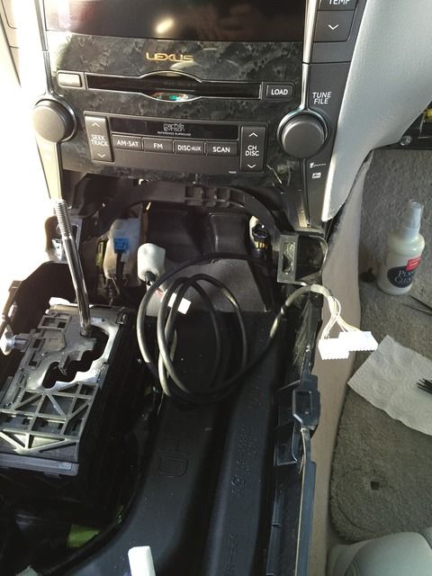
.Then pull the end of the umbilical up through the back of where the ashtray resides…
.
.
.
.
.
.Notice the 5 clips on the backside of the panel and where they’re located…

.
.
.

.
.
.Remove the three (3) phillips screws at the top and two from the bottom of the glovebox…

.
.
.These two (2) rubber rectangular nodules (pointed out by my screwdriver) will prevent the glovebox from falling down once you’ve removed the 3 screws…

.
.
.The glovebox has 2 (black & blue) molex plugs (for interior light and footwell light) you’ll need to unplug in order to fully remove…

.
.
.I found it easier to place the glovebox onto its side. I could then work around things a bit easier prior to fully removing the glovebox…

.
.
.And the glovebox fully removed…

.
.
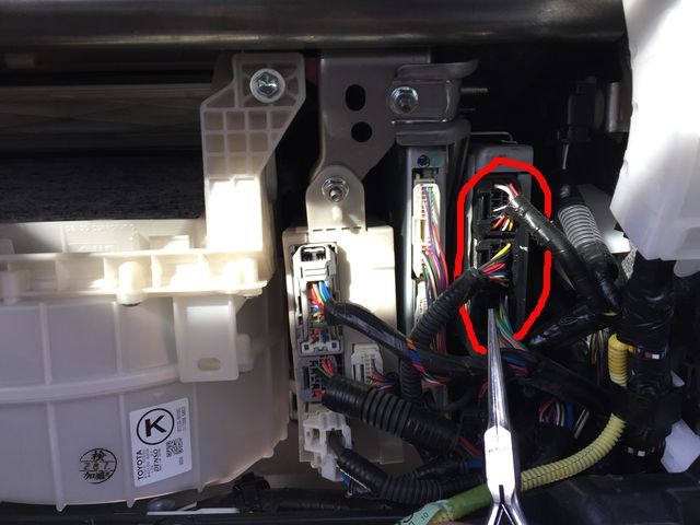
.Now you’ll want to do the following THREE STEPS:
1st. Locate and Remove the (3) OEM (factory) black molex plugs/connectors from the OEM Lowering Module (as circled and pointed to with my needle nose pliers)…

2nd. Plug the Datasystem’s (3) INDVIDUAL molex plugs (1 white, 2 black) into the OEM Lowering Module…

3rd. Plug the loose (3) OEM black molex plugs into the SINGLE LONG black Datasystem female molex receptacle…

.
.
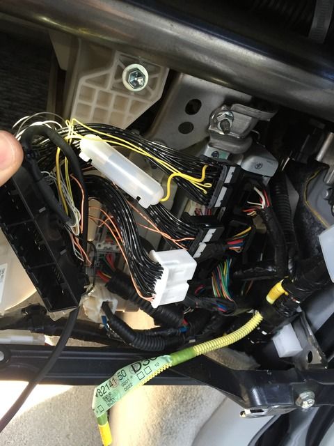
.IMPORTANT: The wires will be very tight. Take you time to manipulate the bends. Ensure the molex plugs are properly seated/locked. Don’t force anything. Just continue to move and massage the wires around until things fit. Patience is your friend here…

.
.
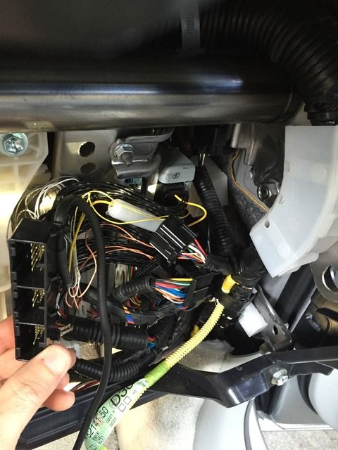
.I decided to coil up some excess Datasystem wiring/umbilical here behind the glovebox. I wanted to avoid having too much extra length at the control module side (near the ashtray)…

.
.
.Then run the umbilical up along the center console. I chose to run the wire INSIDE the center console and not under the carpet. It was an effortless run…

.
.
.Then pull the end of the umbilical up through the back of where the ashtray resides…

.
.
.
Last edited by apaper; 05-30-15 at 01:37 PM.
04-26-15, 10:56 PM
#6
Driver
Thread Starter
Pics 100+…
.
.
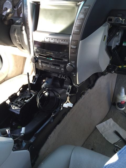
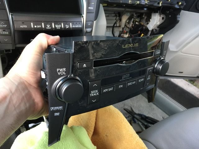
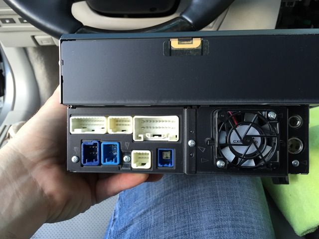
.SIDEBAR/OPTION: I proceeded to remove the OEM CD/DVD player from the dash to access the Datasystem’s “optional” speed-sense control plug/wire/molex, which is located on the back of the OEM Touchscreen. I’ll leave these steps OUT of this thread. PM me for pics or more info. Here’s quick 3 pics of the CD/DVD player removed (just for *****s & giggles)…
.
.
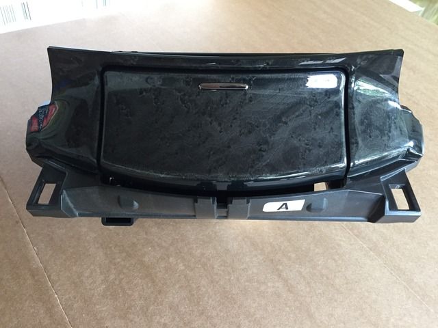
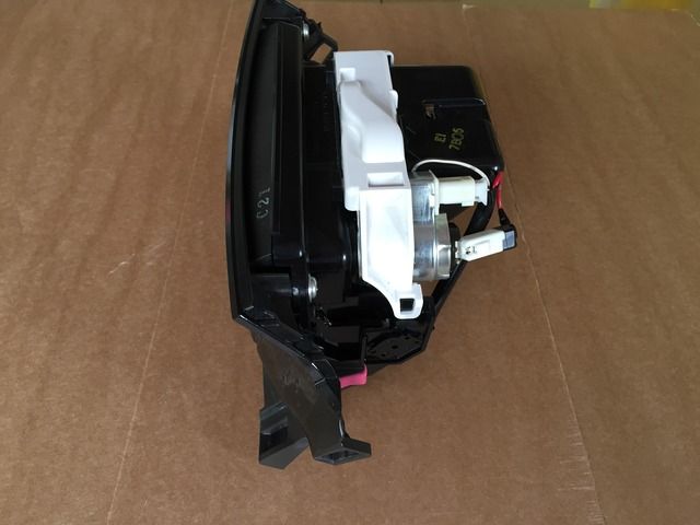
.Now let’s dismantle the ashtray…
.
.
.Side profile, unaltered (before any modifications)…
.
.
.Rear profile, unaltered…
.
.
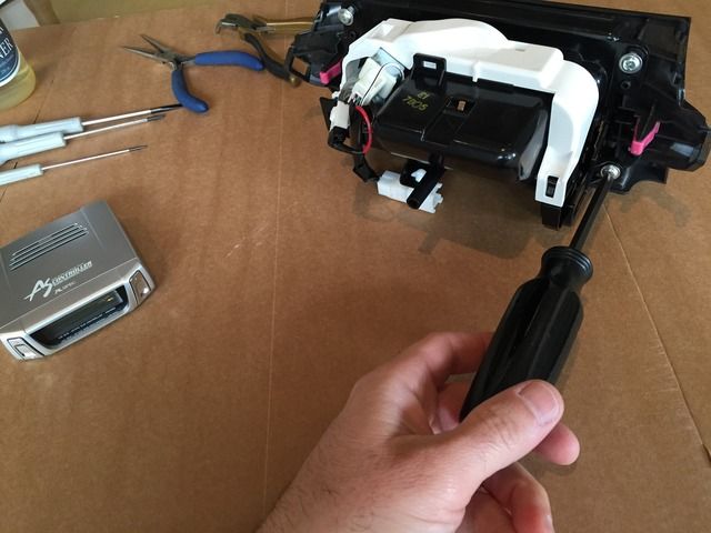
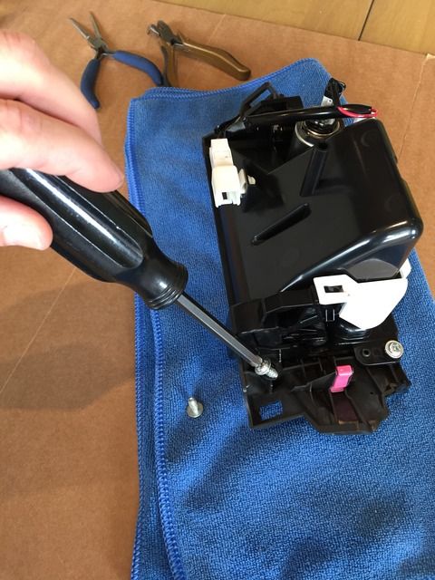
.The back of the ashtray needs to be removed from the front wooden fascia. Four (4) screws hold it together…
.
.
.
.
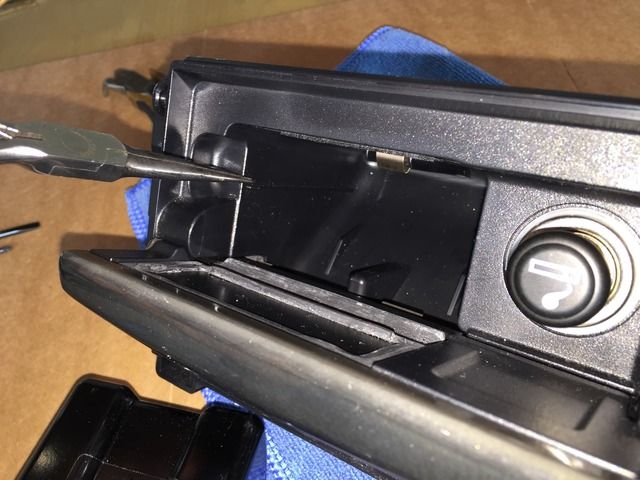
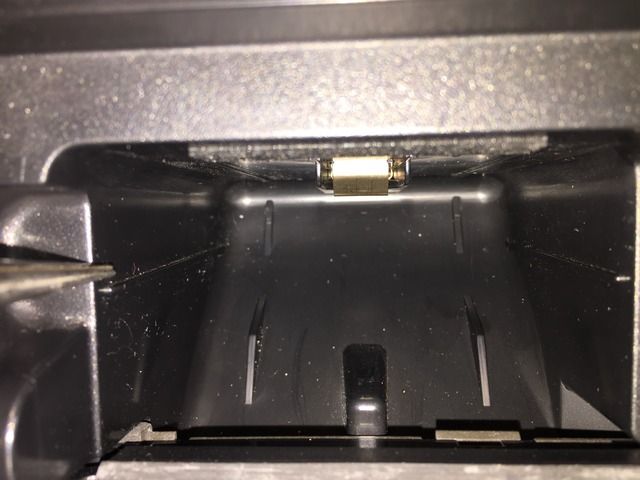
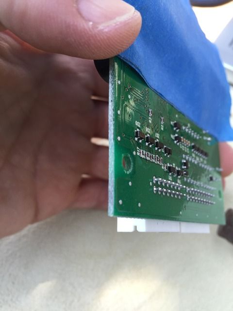
.The Objective Here: to have this factory groove/bump be the ‘guide’ and new ledge for the PCB (printed circuit board) of the controller (Datasystem’s Control Module)…
.
.
.Another angle of the bump/groove…
.
.
.
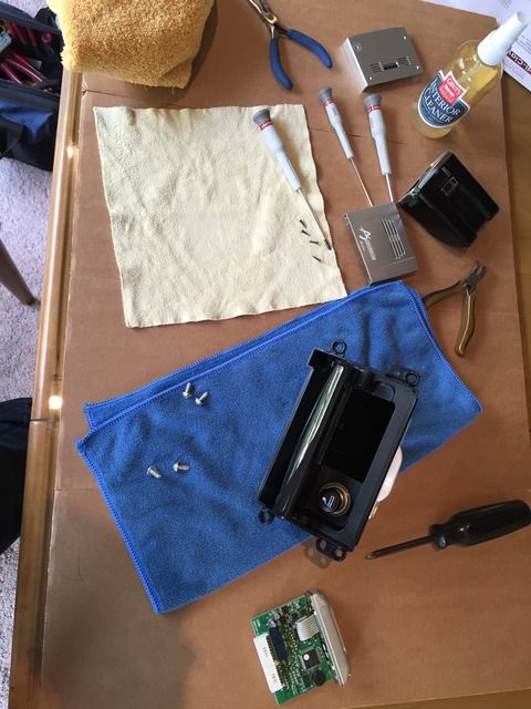
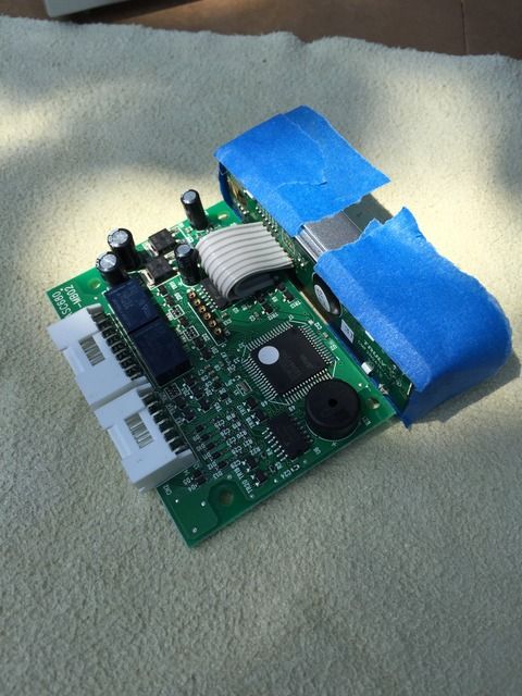
.Now it’s time to tape off the plastic faceplate of the controller. Keeping the silver plastic faceplate on (which we’ll remove later) will allow us to better hold/control the entire assembly as we work on it while reducing potential stress to various pieces…
.
.
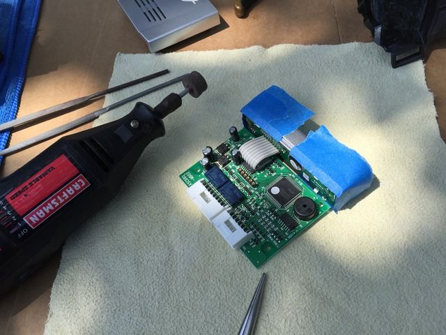
.Time to get out the Dremel grinder/sander…
.
.
.The GOAL: To sand down the sides of the green fiberglass PCB (printed circuit board) so it more easily fits into the opening of the ashtray…
.
.
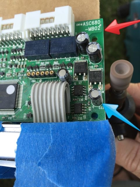
.IMPORTANT: Take down the sides of the PCB, approximately 3/16” on each side (as pointed out in red arrow). You’ll also want to take enough PCB off bet stop the removal when you reach the inner metal core (which you can see through the green PCB). Furthermore, ensure you don’t TOUCH any of the electronics (as pointed out in blue arrow) like the transistors or capacitors...
.
.
.
.
.
.SIDEBAR/OPTION: I proceeded to remove the OEM CD/DVD player from the dash to access the Datasystem’s “optional” speed-sense control plug/wire/molex, which is located on the back of the OEM Touchscreen. I’ll leave these steps OUT of this thread. PM me for pics or more info. Here’s quick 3 pics of the CD/DVD player removed (just for *****s & giggles)…


.
.
.Now let’s dismantle the ashtray…

.
.
.Side profile, unaltered (before any modifications)…

.
.
.Rear profile, unaltered…

.
.
.The back of the ashtray needs to be removed from the front wooden fascia. Four (4) screws hold it together…

.

.

.
.
.The Objective Here: to have this factory groove/bump be the ‘guide’ and new ledge for the PCB (printed circuit board) of the controller (Datasystem’s Control Module)…

.
.
.Another angle of the bump/groove…

.

.
.
.Now it’s time to tape off the plastic faceplate of the controller. Keeping the silver plastic faceplate on (which we’ll remove later) will allow us to better hold/control the entire assembly as we work on it while reducing potential stress to various pieces…

.
.
.Time to get out the Dremel grinder/sander…

.
.
.The GOAL: To sand down the sides of the green fiberglass PCB (printed circuit board) so it more easily fits into the opening of the ashtray…

.
.
.IMPORTANT: Take down the sides of the PCB, approximately 3/16” on each side (as pointed out in red arrow). You’ll also want to take enough PCB off bet stop the removal when you reach the inner metal core (which you can see through the green PCB). Furthermore, ensure you don’t TOUCH any of the electronics (as pointed out in blue arrow) like the transistors or capacitors...

.
.
.
Last edited by apaper; 05-30-15 at 02:25 PM.


Trending Topics


 04-28-15, 09:54 PM
#15
Intermediate
WOW Adam!
You did a Great job on the install and a PHENOMENAL job on the tutorial! That was Really involved and it took some guts to open up and mod that controller box, not too mention all of the pictures! It turned out Great! How do you like it?
Thanks for sharing it!'
By the way, during the ice cream break, was it your birthday? I thought that I saw what looked like a candle in your ice cream. If so, Happy Birthday!
