HOW TO: LS430 Mark Levinson EVERYTHING w/Pics & part#s
 07-06-10, 04:16 PM
#1
Lead Lap
Thread Starter
Car Used: 2001 Lexus LS 430 w/Nav before M/C
Content:
Post 01: Overview and P/Ns (UPDATED 08.07.15)
Post 02: Subwoofer Repair/Replacement (UPDATED 07.08.10)
Post 03: Front Door Speaker replacement (UPDATED 08.06.15)
Post 04: Tweeters (UPDATED 07.18.10)
Post 05: Amplifier (UPDATED 07.23.10)
Post 06: Navigation Override (UPDATED 08.01.10)
Post 07: Nav Tool Installation (NEW 08.06.10)
Post 08: Navigation DVD replacement (UPDATED 08.01.10)
Post 09:
Post 10:
Post 11: Key Batterie replacement
Part Numbers with notes
**Please note that Pioneer speakers cannot be used with ML speakers (tnx wanderer99)
Subwoofer: (p/n 86160-0w260 non ML 86160-50190 after 07.2003 86160-0w260 non ML 86160-50190)
NOTE 1: Infinite baffle 8" JBL sub w/16ohm Diaphragm
NOTE 2: I have used Polk Audio db840DVC 8-Inch Dual Voice Coil Subwoofer for 2 years now and it's amazing (amazon ~$50)
NOTE 3: I have used 4" Gorilla tape to seal off all holes in the rear deck of the the LS where subwoofer sits.
Tweeters Front: (p/n 86160-0W230 non ML 86140-50160 after 07.2003 86160-0w230 non ML 86160-50160)
NOTE: None
Tweeters Rear: (p/n 86160-0WB20 non ML 86160-50200 after 07.2003 86160-0WB30 non ML 86160-50210)
NOTE: None
Door Speakers Front: (p/n 86160-0W240 non ML 86140-50170 after 07.2003 86160-0w240 non ML 86160-50170)
NOTE 1: ML uses 6 3/4" or 6.5"? 8-ohm
NOTE 2: Not all 6.75" fit, you might have to get 6.5" and use long wood screws to screw directly into plastic.
NOTE 3: Front door speakers have a factory crossover, so there is no point in getting 2, 3, or 5 way speakers.
Door Speakers Rear: (p/n 86160-0W250 non ML 86140-50180 after 07.2003 86160-0WA00 non ML 86160-50180)
NOTE 1: ML uses 6.5" 8ohms
NOTE 2: Cruchfield recommends 6.5" 2-way 4ohms
Amplifier in the trunk: (p/n 86280-0W041 non ML 86280-50261 after 07.2003 86280-0W250 non ML 86280-50330)
NOTE: Nakamichi for ML and Pioneer for non ML
HERE IS LINK TO LS430 WIRING (PDF)
Lets start with basics..
What you really need to know:
You will damage speakers AND the amp if amp does not put out enough power for the speakers. You will damage the speakers if your amp puts out more power than speakers require. You will jacked up the over all sound if speakers are not properly matched... for ex Impedance
What you should know:
Ohm's law states that the current through a conductor between two points is directly proportional to the potential difference or voltage across the two points, and inversely proportional to the resistance between them.
How To Understand Impedance?
Speaker Impedance varies with frequency. You will often see Impedance measured in ohms using Ω (the Greek letter Omega). Speaker impedance is different at different frequencies. You can see this by using a multimeter and moving the speaker cone. Most speaker impedance discussions concern nominal impedance which is the approximate DC resistance of the voice coil.
Impedance tells you how much current will pass through a speaker at a specific voltage. Impedance is a way of telling you how much of the voltage introduced at one end will really make it to the other end. A speaker’s impedance influences the ratio of voltage and current. Impedance also depends on other qualities of electricity, such as resistance, reactance, inductance, and capacitance.
Impedance restricts the flow of power from your receiver or amplifier. A lower impedance speaker will accept more power. For example, a 4 ohm speaker will use more power from your amplifier than an 8 ohm speaker. Is this good? Yes and no. A 4 ohm speaker will be louder than an 8 ohm speaker at the same setting, but it will also run hotter. Does that mean a higher impedance is better? No. Impedance that is too high restricts the flow of current, vital current that a speaker needs in order to play loudly.
Impedance is determined by resistance and another value, reactance. Reactance takes into account opposing forces and frequency. Reactance describes the electrical effect of the inductors and capacitors typically found in a speaker’s crossover network. Two elements of reactance, inductance and capacitance, correspond to frequency. Inductance is in proportion to frequency while capacitance is inversely proportional to frequency.
For most average speaker owners, a speaker impedance specification in the 6-8 Ohm range (the most common kind) represents a good compromise between current and voltage. Most amplifiers and receivers can safely drive speakers with 6-8 Ohm spec.
Last edited by RomanTPA; 08-11-15 at 07:03 AM.

The following 5 users liked this post by RomanTPA:
bjchilds1 (12-04-21),
LEVENEZIA (03-26-21),
ltd76gold (05-10-18),
Pughnitive (08-29-19),
Shalmanese (11-07-23)
07-06-10, 04:17 PM
#2
Lead Lap
Thread Starter
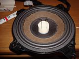
Subwoofer repair and/or installation:
HERE IS LINK TO LS430 WIRING (PDF)
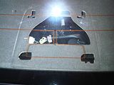
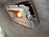
Removing Third Brake Light
1. From the top, slide the entire assembly to the left
2. Pull up on the assembly
3. Unplug the bulb
5. to put it back in, repeat first 3 steps in reverse.
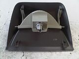
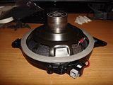
Removing The Sub
1. Pry up the sub cover and/or Remove rear headrests (not required)
2. Pop out the trim thats behind the arm rest
3. Pop out the cover for the bolt to loosen up the back seat (x 3 12mm)
4. Remove 3 nuts the hold the back seat back
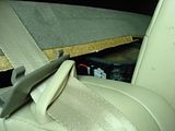
5. Gently pull the seat forward from the top
6. After you get enough clearance, remove the two plugs that hold down deck cover
7. Lift up on the deck cover untill you can get your arm under
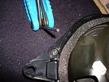
8. Unscrew the sub (x4 10mm)
9. Unplug the sub
10.Pull the sub out
11.Put back together in reverse or continue to read for repair
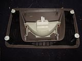
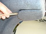
To remove the back dash completely
You have to push down in the far corners, push to the side on the support cover, and then the little locking tab will be disengaged. Do one side at a time. Push down on the dash towards the back, right next to the support arm, in the corner (a little more to the side, but towards the corner). You'll notice that a tab from the support arm cover sticks into a slot on back dash. I just pushed down on the deck until it cleared, then pushed again the support arm cover until the tab was outside the slot, then let up on the dash. Then I repeated for the other side. Now the deck can be pulled out. Be careful here. Do not pull the entire thing by the corners in the front. They are not fully secure. I pulled gently and evenly using the front edge near the middle (but out as far as it felt solid). I would pull a little and then push on the side support covers to make sure nothing was getting caught or scratched.
Slow and steady and it came free. It made getting at the sub MUCH easier. Plus now I can clean that far back edge of the rear dash that can be a pain sometimes.
The seat-belts are still attached at this point, so I just moved the dash forward and leaned it in place of where the rear seat normally goes.
Full follow up on removing rear deck is HERE. Thank you jkukovec
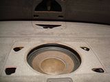

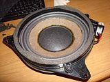
--- Sub Repair ---
(!) Assuming that you have ONLY the sub in front of you (w/out brackets or mounts)
1. Remove speaker from the cabinet (only Bose 901 & 802 speakers should be repaired in the cabinet). Mark the wires and terminals (positive and negative) before you remove the component so you will remember how to correctly reinstall it in the cabinet. The old foam can be messy and sticky so work on newspaper.
2. If you have a gasket, remove it if it is OVER the outer edge of the foam (but do not remove one under the foam if there is one) by inserting a utility knife (or chisel) under the gasket. Carefully pry around the gasket until it can be removed. You can reuse the original gasket or order new ones in most cases. Advent and Dahlquist masonite rings can become brittle so be careful not to break them during removal.
3. Peel or scrape the old foam from the speaker frame and cone and the original gasket if you are re-using it. Remove as much of the old glue as possible without damaging or cutting the cone. Clean any old foam fragments left behind.
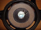
4. In most cases, we suggest that you remove the original dust cap (center circle) see FAQ’s. Do not remove the original dustcap on Infinity Bullet woofers or Bose 901 or 802’s, you will have to center by eye, ear and feel. Gently slice the center of the dustcap and work your way towards the outside of the dustcap (keep the blade horizontal so you will not cut the cone or voice coil leads underneath). Use masking tape to remove any dirt that might be on the inside of the voice coil or in the voice coil gap.
5. Insert vertical strips (about 1/8-1/4″ wide) of shim material inside the voice coil in between the voice coil and magnet pole piece to keep cone/voice coil assembly centered for the refoaming process. Insert them (12:00, 6:00, 3:00, 9:00 etc) until the cone assembly is secure. Be sure they are evenly spaced no matter how many you end up using. Check to insure that the cone and spider assembly are at a natural height and not sunken or elevated.
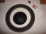
6. Place the new foam surround on the speaker to check for proper fit to the cone and frame. The exact size foam might not be available so you may need to cut, overlap and seam the foam if it is slightly too large and/or trim the outside with scissors. When we refoam, we reglue the new foam in its original place, but you might find it easier to refoam to the front of the cone if the original was adhered to the back. (Advent or Dalquist woofers with masonite rings must have the foam returned to the original location.)
7. Spread a thin, flat bead (shmear with glue tube tip or pen or brush) of glue to the edge of the cone. DO NOT APPLY GLUE TO FOAM. (Glue applied directly to foam will cause foam to curl and be very difficult to work with.) Allow the glue to begin to dry and get tacky. Center the new foam onto cone and gently apply pressure with your finger beginning at the 12:00, 6:00, 3:00 and 9:00 positions. If the new foam is centered correctly, then you can move your finger in a full circle to secure it. Apply glue to speaker frame, let it get tacky and then do the same to the foam on the frame.
8. You may need to trim new gaskets to the correct size. Spread glue on gasket and when tacky, install. You can tape in position. If the gasket is taller than the foam, you can carefully turn upside down on a flat surface to dry. Do not slide. Do not change alignment of foam or gasket. If the foam is taller than gasket, leave speaker face up and place same size component on top of speaker. If you are installing gaskets, then you can use masking tape or clamps to secure. Wait 24 hours and then remove shims from voice coil. Lightly tap to test that cone moves up and down without scraping or grinding. Install new dustcap. It can be larger than the original.
(!)Not all speakers are good candidates for refoaming. The remaining voice coil, spider and cone must be in good shape for refoaming to be successful. If your speaker does not move freely, you might need speaker reconing. This is the removal and replacement of all the moving parts in the speaker frame including the voice coil, cone, spider, surround, dustcap, leads and gasket. In most cases, this returns the component to exact new or upgraded specifications.
(http://www.reconingspeakers.com/faq/...oam-a-speaker/)
Possible replacement sub
What to consider when Looking for a replacement aftermarket sub:
* 8" sub so it can fit in the factory spot
* Infinite Baffle/Free air design, if you want it to sound properly
* Try finding closest to 16ohm, so you will not trip your system protection
* You can have 8ohm dual voice coil ran in a series to make it a 16ohm
* RMS under 100, To keep your amps life longer and not killing it
Here are good and cheap replacements
Power requirements are ok to work with factory amp w/out adding much more stress on it.
Polk Audio db840DVC (What I have been using and loving every second of it)
Size: 8 -inch
Free-Air: No
Impedance: 4 ohms
RMS (Watts): 50-180[
Peak (Watts): 360
Cone Material: Injected Polypropylene
Sensitivity: 85 dB at 1 volt
Dual Voice Coil: Yes = can wire as 8 ohms
Surround Material: Santoprene rubber (This should last much longer than ML)
Top Mount Depth: 4 3/8 inches (a little deep)
Frequency Response: 30 - 200 Hz
Kicker 10C88 Comp 8" 8-ohm subwoofer (This one is closer to ML)
Size: 8 -inch
Free-Air: Yes
Impedance: 8 ohms
RMS (Watts): 50-100
Peak (Watts): 200
Cone Material: Injected Polypropylene
Sensitivity: 85.6 dB at 1 volt
Dual Voice Coil: No
Surround Material: Ribbed foam (this will probably fall apart quick like ML)
Top Mount Depth: 4 1/16 inches
Frequency Response: 30 - 500 Hz
HERE IS LINK TO LS430 WIRING (PDF)
Removing Third Brake Light
1. From the top, slide the entire assembly to the left
2. Pull up on the assembly
3. Unplug the bulb
5. to put it back in, repeat first 3 steps in reverse.


Removing The Sub
1. Pry up the sub cover and/or Remove rear headrests (not required)
2. Pop out the trim thats behind the arm rest
3. Pop out the cover for the bolt to loosen up the back seat (x 3 12mm)
4. Remove 3 nuts the hold the back seat back
5. Gently pull the seat forward from the top
6. After you get enough clearance, remove the two plugs that hold down deck cover
7. Lift up on the deck cover untill you can get your arm under
8. Unscrew the sub (x4 10mm)
9. Unplug the sub
10.Pull the sub out
11.Put back together in reverse or continue to read for repair
To remove the back dash completely
You have to push down in the far corners, push to the side on the support cover, and then the little locking tab will be disengaged. Do one side at a time. Push down on the dash towards the back, right next to the support arm, in the corner (a little more to the side, but towards the corner). You'll notice that a tab from the support arm cover sticks into a slot on back dash. I just pushed down on the deck until it cleared, then pushed again the support arm cover until the tab was outside the slot, then let up on the dash. Then I repeated for the other side. Now the deck can be pulled out. Be careful here. Do not pull the entire thing by the corners in the front. They are not fully secure. I pulled gently and evenly using the front edge near the middle (but out as far as it felt solid). I would pull a little and then push on the side support covers to make sure nothing was getting caught or scratched.
Slow and steady and it came free. It made getting at the sub MUCH easier. Plus now I can clean that far back edge of the rear dash that can be a pain sometimes.
The seat-belts are still attached at this point, so I just moved the dash forward and leaned it in place of where the rear seat normally goes.
Full follow up on removing rear deck is HERE. Thank you jkukovec


--- Sub Repair ---
(!) Assuming that you have ONLY the sub in front of you (w/out brackets or mounts)
1. Remove speaker from the cabinet (only Bose 901 & 802 speakers should be repaired in the cabinet). Mark the wires and terminals (positive and negative) before you remove the component so you will remember how to correctly reinstall it in the cabinet. The old foam can be messy and sticky so work on newspaper.
2. If you have a gasket, remove it if it is OVER the outer edge of the foam (but do not remove one under the foam if there is one) by inserting a utility knife (or chisel) under the gasket. Carefully pry around the gasket until it can be removed. You can reuse the original gasket or order new ones in most cases. Advent and Dahlquist masonite rings can become brittle so be careful not to break them during removal.
3. Peel or scrape the old foam from the speaker frame and cone and the original gasket if you are re-using it. Remove as much of the old glue as possible without damaging or cutting the cone. Clean any old foam fragments left behind.
4. In most cases, we suggest that you remove the original dust cap (center circle) see FAQ’s. Do not remove the original dustcap on Infinity Bullet woofers or Bose 901 or 802’s, you will have to center by eye, ear and feel. Gently slice the center of the dustcap and work your way towards the outside of the dustcap (keep the blade horizontal so you will not cut the cone or voice coil leads underneath). Use masking tape to remove any dirt that might be on the inside of the voice coil or in the voice coil gap.
5. Insert vertical strips (about 1/8-1/4″ wide) of shim material inside the voice coil in between the voice coil and magnet pole piece to keep cone/voice coil assembly centered for the refoaming process. Insert them (12:00, 6:00, 3:00, 9:00 etc) until the cone assembly is secure. Be sure they are evenly spaced no matter how many you end up using. Check to insure that the cone and spider assembly are at a natural height and not sunken or elevated.
6. Place the new foam surround on the speaker to check for proper fit to the cone and frame. The exact size foam might not be available so you may need to cut, overlap and seam the foam if it is slightly too large and/or trim the outside with scissors. When we refoam, we reglue the new foam in its original place, but you might find it easier to refoam to the front of the cone if the original was adhered to the back. (Advent or Dalquist woofers with masonite rings must have the foam returned to the original location.)
7. Spread a thin, flat bead (shmear with glue tube tip or pen or brush) of glue to the edge of the cone. DO NOT APPLY GLUE TO FOAM. (Glue applied directly to foam will cause foam to curl and be very difficult to work with.) Allow the glue to begin to dry and get tacky. Center the new foam onto cone and gently apply pressure with your finger beginning at the 12:00, 6:00, 3:00 and 9:00 positions. If the new foam is centered correctly, then you can move your finger in a full circle to secure it. Apply glue to speaker frame, let it get tacky and then do the same to the foam on the frame.
8. You may need to trim new gaskets to the correct size. Spread glue on gasket and when tacky, install. You can tape in position. If the gasket is taller than the foam, you can carefully turn upside down on a flat surface to dry. Do not slide. Do not change alignment of foam or gasket. If the foam is taller than gasket, leave speaker face up and place same size component on top of speaker. If you are installing gaskets, then you can use masking tape or clamps to secure. Wait 24 hours and then remove shims from voice coil. Lightly tap to test that cone moves up and down without scraping or grinding. Install new dustcap. It can be larger than the original.
(!)Not all speakers are good candidates for refoaming. The remaining voice coil, spider and cone must be in good shape for refoaming to be successful. If your speaker does not move freely, you might need speaker reconing. This is the removal and replacement of all the moving parts in the speaker frame including the voice coil, cone, spider, surround, dustcap, leads and gasket. In most cases, this returns the component to exact new or upgraded specifications.
(http://www.reconingspeakers.com/faq/...oam-a-speaker/)


Possible replacement sub
What to consider when Looking for a replacement aftermarket sub:
* 8" sub so it can fit in the factory spot
* Infinite Baffle/Free air design, if you want it to sound properly
* Try finding closest to 16ohm, so you will not trip your system protection
* You can have 8ohm dual voice coil ran in a series to make it a 16ohm
* RMS under 100, To keep your amps life longer and not killing it
Here are good and cheap replacements
Power requirements are ok to work with factory amp w/out adding much more stress on it.
Polk Audio db840DVC (What I have been using and loving every second of it)
Size: 8 -inch
Free-Air: No
Impedance: 4 ohms
RMS (Watts): 50-180[
Peak (Watts): 360
Cone Material: Injected Polypropylene
Sensitivity: 85 dB at 1 volt
Dual Voice Coil: Yes = can wire as 8 ohms
Surround Material: Santoprene rubber (This should last much longer than ML)
Top Mount Depth: 4 3/8 inches (a little deep)
Frequency Response: 30 - 200 Hz
Kicker 10C88 Comp 8" 8-ohm subwoofer (This one is closer to ML)
Size: 8 -inch
Free-Air: Yes
Impedance: 8 ohms
RMS (Watts): 50-100
Peak (Watts): 200
Cone Material: Injected Polypropylene
Sensitivity: 85.6 dB at 1 volt
Dual Voice Coil: No
Surround Material: Ribbed foam (this will probably fall apart quick like ML)
Top Mount Depth: 4 1/16 inches
Frequency Response: 30 - 500 Hz
Last edited by RomanTPA; 08-06-15 at 02:45 PM.
07-06-10, 04:17 PM
#3
Lead Lap
Thread Starter
Door Speakers Front & Rear:
What is mid-range speakers?
The midrange of the sound spectrum is of critical importance, as this is where the heart of the music lies. Vocals and instruments should sound natural and detailed, not too prominent or recessed, nor too bright or too dull. A midrange speaker is usually much smaller than a woofer, but with a radiating surface area greater than the typical tweeter. It reproduces the mid frequency range from approximately 300 to 5000 Hertz.
Three-way or triaxial speakers take the separate woofer and tweeter from a two-way design and add a dedicated midrange driver. This arrangement can produce a more uniform response, depending on how well it is designed. With the inclusion of a midrange driver in any system, the design of the crossover must be more precise.
How to replace front door speakers
Your problem is probably some buzzing coming from the speakers, and honestly there are 3 ways to get the "unce" back in your LS
1. New ML front speaker (Toyota p/n 86160-0W240) which will run you ~$125 per speaker + 30min of work
2. Re-foam the speaker (almost always you can just re-foam it) ~$25/ea + hours of prepping, glueing, and waiting.
3. (what I did) Find closest matching aftermarket alternative and hope for the best. ~$65 for 2 speakers +30 min of work.
6 3/4" Kickers don't fit in the front! Too big and 6.5 is a bit small! Also Kicker 40CS654 6.5" 2-way sound terrible.
Ordering Polk Audio DB651 6.5-Inch Coaxial Speakers. Previous owner had those installed front and back. Sounded great before Front-Driver speaker blew up.
Front doors have a crossover built in, so the speakers will only get mid-range sound and tweeters will pick-up the highs.
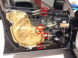
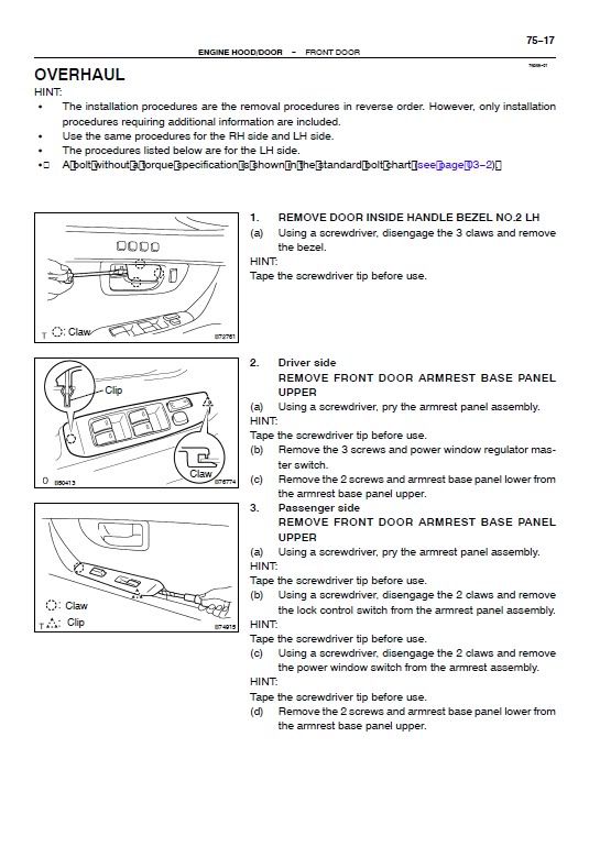
Working on passenger front door first
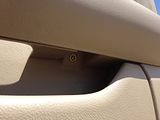
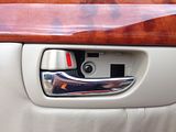
1. Remove cover plate behind the door open handle
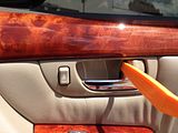
2. Remove the screw
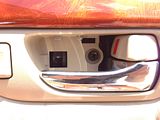
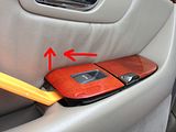
3. Pull up from the back, then pull back an an angle the switch controls
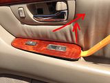
4. Disconnect the plugs
5. Remove the screw that was exposed by removing the switches
6. Remove the screw inside of the door ac/defroster hole

7. Remove the screw hidden under door grab handle
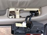
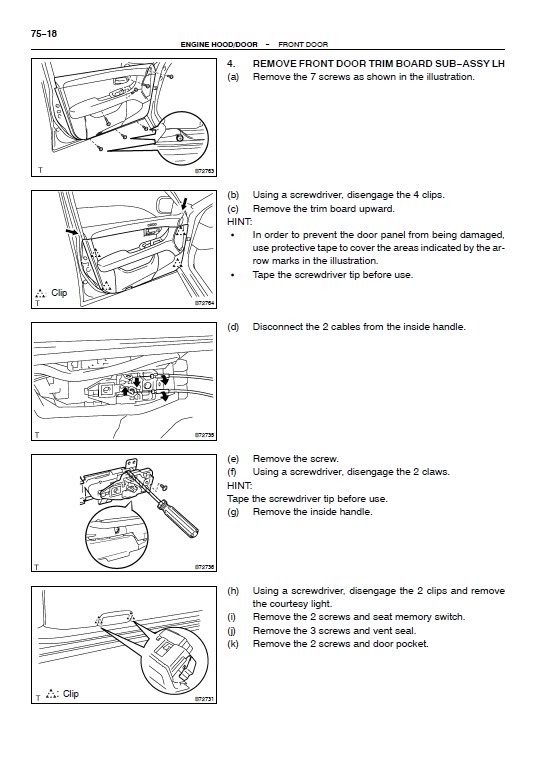
8. Remove 3 screws at the base of the door
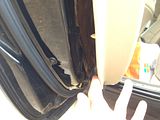
9. Starting from the bottom, gently pry around the door to pop the door panel off, then lift up to remove
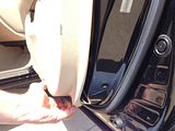
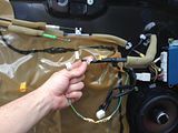
10. Disconnect: door lock, door handle, other plugs, and the plug for puddle light at base of the door.
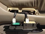
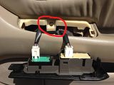
Here are all of the things that needs to be disconnected passenger-front
Driver side is just about 99% identical
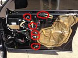
-Unscrew speakers
-Crimp or solder new wires for aftermarket speakers
-Screw in new speakers
-Test that they work and don't vibrate
-Perform steps 10-1 in reverse order.
How to replace rear door speakers
Working with Driver-Rear door
1. Remove cover plate behind the door open handle

2. Remove the screw that is now exposed
3. Pull up from the back, then pull back an an angle the switch controls
4. Disconnect the plug and gently pull the light straight out
5. Remove the screw that was exposed by removing the switches
6. Remove the screw hidden under door grab handle
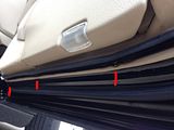
7. Remove the plastic cover from the pillar dividing windows (held in by 2 clips behind it)
8. Remove 3 screws at the base of the door, you might have to flip up the rubber guard
9. Starting from the bottom, gently pry around the door to pop the door panel off, then lift up to remove
10. Disconnect: door lock, door handle, other plug, and the plug for puddle light at base of the door.
-Unscrew speakers
-Crimp or solder new wires for aftermarket speakers
-Screw in new speakers
-Test that they work and don't vibrate
-Perform steps 10-1 in reverse order.
HERE IS LINK TO LS430 WIRING (PDF)
Here is FSM instructions for removing door panels: LHD '04 LS430 w/ML

What is mid-range speakers?
The midrange of the sound spectrum is of critical importance, as this is where the heart of the music lies. Vocals and instruments should sound natural and detailed, not too prominent or recessed, nor too bright or too dull. A midrange speaker is usually much smaller than a woofer, but with a radiating surface area greater than the typical tweeter. It reproduces the mid frequency range from approximately 300 to 5000 Hertz.
Three-way or triaxial speakers take the separate woofer and tweeter from a two-way design and add a dedicated midrange driver. This arrangement can produce a more uniform response, depending on how well it is designed. With the inclusion of a midrange driver in any system, the design of the crossover must be more precise.
How to replace front door speakers
Your problem is probably some buzzing coming from the speakers, and honestly there are 3 ways to get the "unce" back in your LS
1. New ML front speaker (Toyota p/n 86160-0W240) which will run you ~$125 per speaker + 30min of work
2. Re-foam the speaker (almost always you can just re-foam it) ~$25/ea + hours of prepping, glueing, and waiting.
3. (what I did) Find closest matching aftermarket alternative and hope for the best. ~$65 for 2 speakers +30 min of work.
6 3/4" Kickers don't fit in the front! Too big and 6.5 is a bit small! Also Kicker 40CS654 6.5" 2-way sound terrible.
Ordering Polk Audio DB651 6.5-Inch Coaxial Speakers. Previous owner had those installed front and back. Sounded great before Front-Driver speaker blew up.
Front doors have a crossover built in, so the speakers will only get mid-range sound and tweeters will pick-up the highs.
Working on passenger front door first
1. Remove cover plate behind the door open handle

2. Remove the screw

3. Pull up from the back, then pull back an an angle the switch controls

4. Disconnect the plugs

5. Remove the screw that was exposed by removing the switches

6. Remove the screw inside of the door ac/defroster hole

7. Remove the screw hidden under door grab handle

8. Remove 3 screws at the base of the door

9. Starting from the bottom, gently pry around the door to pop the door panel off, then lift up to remove

10. Disconnect: door lock, door handle, other plugs, and the plug for puddle light at base of the door.
Here are all of the things that needs to be disconnected passenger-front

Driver side is just about 99% identical

-Unscrew speakers
-Crimp or solder new wires for aftermarket speakers
-Screw in new speakers
-Test that they work and don't vibrate
-Perform steps 10-1 in reverse order.
How to replace rear door speakers
Working with Driver-Rear door
1. Remove cover plate behind the door open handle

2. Remove the screw that is now exposed

3. Pull up from the back, then pull back an an angle the switch controls

4. Disconnect the plug and gently pull the light straight out

5. Remove the screw that was exposed by removing the switches

6. Remove the screw hidden under door grab handle

7. Remove the plastic cover from the pillar dividing windows (held in by 2 clips behind it)

8. Remove 3 screws at the base of the door, you might have to flip up the rubber guard

9. Starting from the bottom, gently pry around the door to pop the door panel off, then lift up to remove

10. Disconnect: door lock, door handle, other plug, and the plug for puddle light at base of the door.

-Unscrew speakers
-Crimp or solder new wires for aftermarket speakers
-Screw in new speakers
-Test that they work and don't vibrate
-Perform steps 10-1 in reverse order.
HERE IS LINK TO LS430 WIRING (PDF)
Here is FSM instructions for removing door panels: LHD '04 LS430 w/ML
Last edited by RomanTPA; 08-11-15 at 07:05 AM.
07-06-10, 04:18 PM
#4
Lead Lap
Thread Starter
Tweeters:
write up coming eventually...
HERE IS LINK TO LS430 WIRING (PDF)
To remove the plastic cover in the dash thats covering up the tweeters:
1. Use a flat screwdriver covered with cloth (so you dont scratch the dash)
2. There is a clip on the about 5'oclock position for the Lleft speaker
3. 7 o'clock position for the Right Speaker that you can pry up on to get the grill off.
What is a tweeter?
Highs are reproduced by the tweeter, a small driver separate in many systems, but mounted in front of woofer cones in multidriver 2 and 3 way car speakers. Tweeters provide the sizzle and sibilance that give a more lifelike sense of presence to the experience of music. They come in three common types: Cones, Domes, and horns.
Cone tweeters are efficient and the most economical. They have a limited dispersion pattern.
Dome tweeters - the type found in most home speakers - have a more linear response and are more accurate with much wider dispersion pattern than any other type.
Horn Tweeters are powered either by a dynamic (magnet & coil) diaphragm, or by a Piezo driver. They are the most powerful high frequency emitter but more directional, and may lack the extended range of the domes.
Originally Posted by Jabberwock:
Yep if someone has specs on the crossover it makes for absoluetly identical speaker frequency matching but with most modern speakers they have plenty of overlapping freq range so it really would not be a problem matching replacement speakers to 90% of crossovers. When in doubt get the replacement speaker with a slightly wider freq range and it will be fine. In most case as long as you don't go completely backwards - ie. wire the tweeter to the low band (crossover wiring to sub) and the sub speaker to the high band (tweeter), it should be fine. For instance if the crossover is a 2 way and its cutting 3500-4000hz and above to high then make sure the tweeter freq range specs is something like 3000hz- 16khz. If you mistakenly used a tweeter with specs of 4000hz-16khz you would have a "hole" in response between 3500hz and 4khz.
Yep if someone has specs on the crossover it makes for absoluetly identical speaker frequency matching but with most modern speakers they have plenty of overlapping freq range so it really would not be a problem matching replacement speakers to 90% of crossovers. When in doubt get the replacement speaker with a slightly wider freq range and it will be fine. In most case as long as you don't go completely backwards - ie. wire the tweeter to the low band (crossover wiring to sub) and the sub speaker to the high band (tweeter), it should be fine. For instance if the crossover is a 2 way and its cutting 3500-4000hz and above to high then make sure the tweeter freq range specs is something like 3000hz- 16khz. If you mistakenly used a tweeter with specs of 4000hz-16khz you would have a "hole" in response between 3500hz and 4khz.
Last edited by RomanTPA; 04-22-11 at 11:30 PM.
The following users liked this post:
nathe4120 (11-30-17)
07-06-10, 04:19 PM
#5
Lead Lap
Thread Starter
Amplifier:
HERE IS LINK TO LS430 WIRING (PDF)
2001 Lexus LS430 Car Stereo Radio Wiring Diagram
Radio Constant 12V+ Wire: Blue/Yellow
Car Radio Accessory Switched 12v+ Wire: Gray
Radio Ground Wire: Brown
Radio Illumination Wire: Green
Radio Dimmer Wire: White/Green (thank you: REV-01)
*Radio Power Antenna Trigger Wire: Black/Red
*Radio Amplifier Turn On Trigger Wire: White/Blue
Amplifier Output Wire Colors (at Amplifier):
Left Front Tweeter Wire (+): Pink
Left Front Tweeter Wire (-): Violet
Right Front Tweeter Wire (+): Light Green
Right Front Tweeter Wire (-): Blue
Left Rear Mid Speaker Wire (+): Black
Left Rear Mid Speaker Wire (-): White
Right Rear Mid Speaker Wire (+): Red
Right Rear Mid Speaker Wire (-): White
*Left Rear Subwoofer Speaker Wire (+): Black/white
*Left Rear Subwoofer Speaker Wire (-): Yellow/Red
*Right Rear Subwoofer Speaker Wire (+): Red/White
*Right Rear Subwoofer Speaker Wire (-): White/Blue
Wire Colors at Speakers:
Front Speakers Size: 6 3/4"
Rear Speakers Size: 6 1/2" (not exact size)
Left Front Speaker Wire (+): Pink
Left Front Speaker Wire (-): Purple
Right Front Speaker Wire (+): Light Green
Right Front Speaker Wire (-): Blue
Left Rear Speaker Wire (+): Black
Left Rear Speaker Wire (-): Yellow
Right Rear Speaker Wire (+): Red
Right Rear Speaker Wire (-): White
* = not confirmed
What you need to know before asking amp related questions
Understanding Amplifier Power Ratings
A watt itself is a unit of energy that can be correctly described as the power used when energy is expended at the rate of one joule per second. A Joule is a quantity of work or heat that is generated equivalent to the force of one Newton moving an object at the point of application, a distance of one meter.
Now this wonderfully concise physical description can be as well applied to the actions of amplifiers upon their loads (speakers) as it can to any other phenomenon. When electrical power generated by the amplifier is applied to a load to do work, (move a cone back and forth) the resulting energy expenditure can be uniformly measured in a standard way, and applied to all other similar situations.
There is only one comparative power designation that is truly helpful, and that is:
RMS, which stands for Root Mean Square, the only reasonably accurate, consistent, comparative measurement of power exchange that should be used for both amplifiers and speakers. RMS is an average of the power transfer between a generator and normative load that is obtained by measuring the AC power with the formula P=EI cosine � where cos. � is the power factor.
Generally (but not always), RMS is half or less of the value usually attributed to alternative methods such as: Peak power, Max power, IPP - Instantaneous Peak Power, PMPO - Peak Music Power Output, and other measurement methods, that while having a nebulous mathematical consistency, are still little more than schemes to create higher numbers to increase sales. Some manufacturers of low price components have recently taken to promoting power figures of as much as 10 times the RMS specification. Be wary ...very wary!
Many manufacturers provide specifications without mentioning what kind of watts are being measured. Again, this almost always means that those are not RMS watts, and the actual power is half or less (often, much less) than the number indicated.
Where are Watts Found
It is important to remember that amplifiers create an amount of electrical potential that does not become watts untill the energy is converted to another form. This happens in the speaker, where the voice coil consumes watts of electrical energy as it converts it to sound amplitude as measured in decibels.
Multiple power points
Another favorite trick is to just throw out a number for woofers with two voice coils or amplifiers with 2 or 4 channels. This invariably turns out to be the maximum watts for all functions. So:
"300 MAX watts Four Channel Amplifier" really means 150 watts RMS divided into four channels or 37.5 watts RMS per channel. Often it can mean less. Decidedly less impressive, eh? Or, for a woofer, "400 watt dual voice coil woofer" really means 200 watts RMS divided by two coils or 100 watts RMS per coil. This could yield disappointing results. Unfortunately, these descriptions are not always consistent. If they were, it would be easier for consumers to pin them down.
Bridging
But that's not all! There are plenty more complications where these came from. For instance in amplifiers, there are amps with not only multiple channels, but the capability of being bridged. This means that any two (but only two) channels can be bridged to form an amplifier of approximately double the capacity of a single channel. It does this by taking a mono input signal and dividing it between the positive peaks of the signal and the negative valleys, and amplifying each separately. These separated polarities are then reunited at the amplifier terminals to form a unified signal again for the woofer.
Thus, two 75 watt RMS amplifiers can become a single 150 watt RMS amp. In a four channel bridgeable amplifier, four can be come two, each with twice the power of a single channel.
But look out here! Most amplifiers are of the class AB variety. this means they can be bridged to a 4 ohm load only, yet some brands advertise the total of the 2 ohm load each channel can carry separately. This is very misleading and should not be confused with the amplifiers described in the next paragraph.
Multiple power ratings
While 4 ohm remains the industry standard for many car amps and single coil woofers, capacities are tending downward, mostly because of the increase in the watt numbers attendant to lower impedance carrying ability. At a minimum, better quality units will list "2 ohm Stable" as a feature. Since most speaker loads are highly variable in operation, and will have occasions when operational impedance of a 4 ohm system can go below 2 ohms, it is good to have this capacity so that distortion is reduced at high amplitudes, especially.
Dual voice coil woofers can have coils that are 1, 2, 3, 4, 6, and 8 ohms. This means that such woofers can be configured to operate either singly or separately at the most efficient level. These woofers can be connected in a variety of ways to the multiple impedance amplifiers. Dual voice coils can be connected either in parallel or serial circuits. A woofer with two 4-ohm coils connected serially would produce an 8-ohm total, or in parallel (with both + terminals and both - terminals tied to one set of amplifier terminals) a 2-ohm load. Of course, a single voice coil can be used also, albeit at half the rated power. Check our Impedance Calcultor to get it right.
With two woofers connected in a serial circuit, two 2-ohm woofers can present a 4 ohm load, or two 1 ohm woofers can present a 2 ohm load.
The best common configuration is to use two dual voice coil woofers with 4 ohm coils. All four coils in parallel will make a highly efficient 1 ohm load, with power handling equal to the total RMS of both woofers.
But in all cases, the idea is to match both the impedance and the output power capacity of both the amp and woofer units. A good relationship is for the Amplifier to supply between 10 to 40 percent more power to the woofer than the woofer's nominal RMS watt handling rating. Thus, a 200 watt woofer should optimally have a 225 to 280 watt amplifier channel connected to it.
(http://www.thespeakerstore.com/gloss...ndingspecs.htm)
Last edited by RomanTPA; 04-22-11 at 11:31 PM.
The following users liked this post:
nathe4120 (11-30-17)
07-06-10, 04:19 PM
#6
Lead Lap
Thread Starter
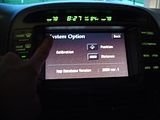
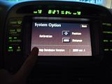
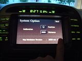
Nav Override:
How to take out radio/nav is... HERE, HERE, and HERE;
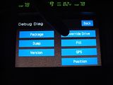
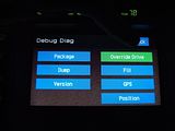
Nav Override
Allows you to use every feature of your touch screen while driving.
Also has some info you might want to know, like your DVD version.
How to enable it:
0. You have to re-do this every time you turn the car off/on
1. Car must not be moving
2. [tap] Argee
3. [press] Menu
4. [tap] System option
5. [tap] Top left corner of the screen
6. [tap] Bottom left corner of the screen
7. [tap] Top left of the screen
8. [tap] Bottom left of the screen
9. [tap] Bottom right of the screen
10.[tap] Override Drive
11.[tap] Back


How to take out radio/nav is... HERE, HERE, and HERE;
Nav Override
Allows you to use every feature of your touch screen while driving.
Also has some info you might want to know, like your DVD version.
How to enable it:
0. You have to re-do this every time you turn the car off/on
1. Car must not be moving
2. [tap] Argee
3. [press] Menu
4. [tap] System option
5. [tap] Top left corner of the screen
6. [tap] Bottom left corner of the screen
7. [tap] Top left of the screen
8. [tap] Bottom left of the screen
9. [tap] Bottom right of the screen
10.[tap] Override Drive
11.[tap] Back


Last edited by RomanTPA; 08-15-10 at 05:29 AM.
07-06-10, 04:20 PM
#7
Lead Lap
Thread Starter
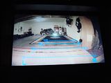
[SIZE="3"]Adding a back up camera to your Mark Levinson Nav[/SIZE]
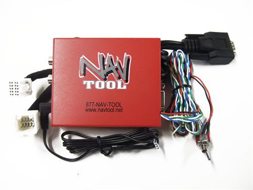
NavTool is not exactly plug-and play device, you have to connect some other wires also
however it is a generic video converter box which you can take with you to your new car
the only thing you will need to get another car specific wiring harness
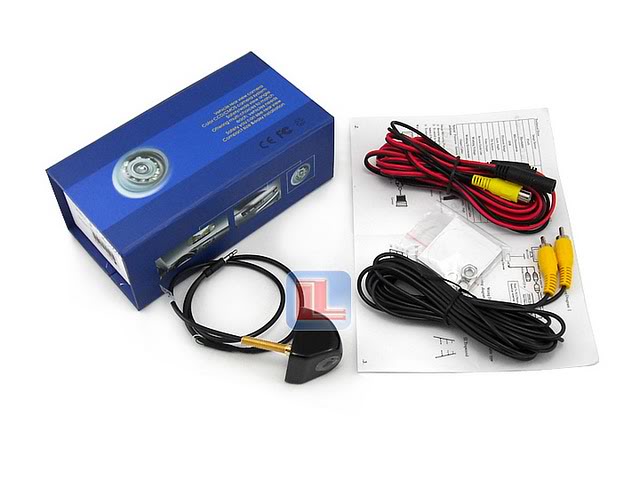
this is the camera that i have purchased from ebay for my installation
But you can use any camera that has the RCA video cable
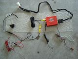
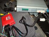
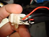
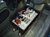
This is what the entire kit looks like
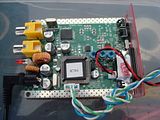
I thought that there were way too many extra/unwanted wires on the tool
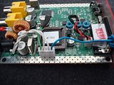
I soldered the 2 white wires to the (-) part of the power connector.
Cut off the green ebrake wire and capped it off
cut off and looped the red and black wire that went to the switch
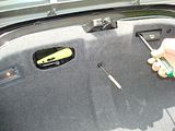
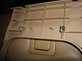
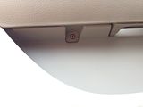
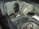
You will need to remove most of the trunk interrior for a clean install
Pull out the light and unplug it
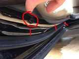
pop off the covers for the tail light that are in the corners
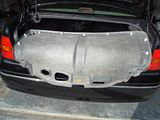
pop out the rest of the liner
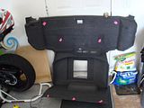
Marked spots is what holds it up
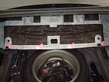
pull it back to get those clips out
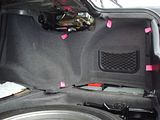
marks is where clips are
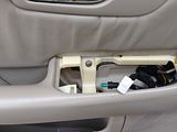
you will also need to remove trim from around the tool box
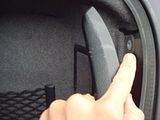
thats why i posted this shot ^ pop this peice out prior to trying to remove that
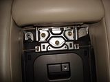
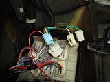
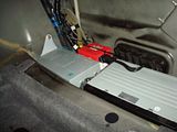
this is what the back of you nav looks like
see that medium sized white connector in the middle?
thats where the "Y" harness will plug in from Nav Tool
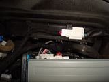
you can do it w/o removing the navigation
I just pulled it to take a better picture
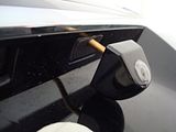
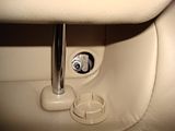
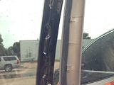
I took out that plastic peice and drilled it for the camera
ran the power to the tail light harness
soldered it to the ground (-) and reverse (+)
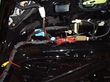
power for Nav tool was taken from the fuse box on the left side of the trunk
using the volt meter found what is acc and which one was reverse light
then just connect the wires
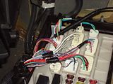
and plug it back in
i found a nicely fitting spot for the nav tool and tied it down to it
NavTool is not exactly plug-and play device, you have to connect some other wires also
however it is a generic video converter box which you can take with you to your new car
the only thing you will need to get another car specific wiring harness
this is the camera that i have purchased from ebay for my installation
But you can use any camera that has the RCA video cable

This is what the entire kit looks like

I thought that there were way too many extra/unwanted wires on the tool

I soldered the 2 white wires to the (-) part of the power connector.
Cut off the green ebrake wire and capped it off
cut off and looped the red and black wire that went to the switch

You will need to remove most of the trunk interrior for a clean install

Pull out the light and unplug it

pop off the covers for the tail light that are in the corners

pop out the rest of the liner

Marked spots is what holds it up

pull it back to get those clips out

marks is where clips are
you will also need to remove trim from around the tool box

thats why i posted this shot ^ pop this peice out prior to trying to remove that

this is what the back of you nav looks like
see that medium sized white connector in the middle?
thats where the "Y" harness will plug in from Nav Tool

you can do it w/o removing the navigation
I just pulled it to take a better picture

I took out that plastic peice and drilled it for the camera

ran the power to the tail light harness

soldered it to the ground (-) and reverse (+)

power for Nav tool was taken from the fuse box on the left side of the trunk

using the volt meter found what is acc and which one was reverse light

then just connect the wires

and plug it back in

i found a nicely fitting spot for the nav tool and tied it down to it

Last edited by RomanTPA; 12-28-16 at 08:47 AM.
Trending Topics
07-06-10, 04:20 PM
#8
Lead Lap
Thread Starter
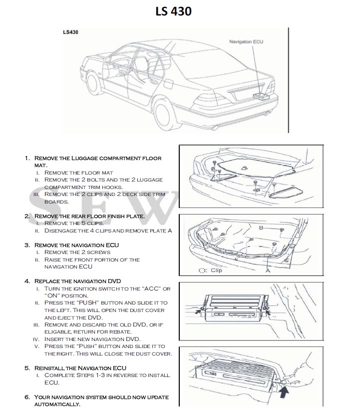
What GEN do I have?... How Do I replace the disk?... Why N.P.H. is gay?...
From http://lexus.sewellparts.com
** You cannot use discs that are different version from your actual NAV unit, it WILL fail
** You can burn a copy onto a dual layer DVD, BUT, NAV will only read couple of brands not all


From http://lexus.sewellparts.com
** You cannot use discs that are different version from your actual NAV unit, it WILL fail
** You can burn a copy onto a dual layer DVD, BUT, NAV will only read couple of brands not all
Last edited by RomanTPA; 11-23-10 at 09:51 AM.
07-06-10, 05:54 PM
#11
Lead Lap
Thread Starter
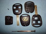
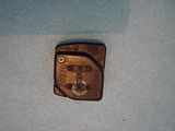
How to replace your key battery
might as well throw this in...
how to replace your key battery and/or key cover
battery cross ref is cr1616 and its 3V
might as well throw this in...
how to replace your key battery and/or key cover
battery cross ref is cr1616 and its 3V


Last edited by RomanTPA; 07-15-10 at 03:27 AM.


