All my crazy Lexus issues SOLVED!! (ECU-leaking capacitor)


 06-09-14, 03:18 PM
#827

Ok, so I have a 96 LS400
You listed these for my model
1995-97 LS400 needs 6 caps as follows:
Qty. 2 of 10uF - 50v
Qty. 1 of 47uF - 63v
Qty. 2 of 100uF - 10v
Qty. 1 of 220uF - 16v
Yet there are no links for a 100uF - 10v OR 220uF - 16v....
Only 100uF linked are 35 and 50v
Only 220uF linked are 50v
Are those fine to use?
Also, on average how much would a reputable company charge to replace them?
I'm thinking the best place to get this done would be someone who works on computers a great deal, or an actual computer shop?
Last edited by Caniac14; 06-09-14 at 05:15 PM.
06-10-14, 11:57 AM
#828
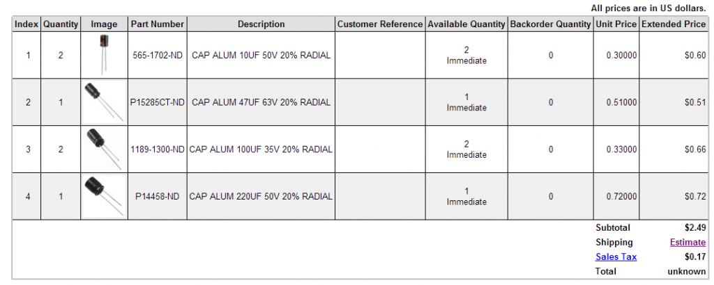
Ok so I just ordered mine. Pretty awesome how cheap it all is too 
I'm not sure how much these weigh but it can't be over 8oz I don't think, so I chose USPS next day shipping for just under $4. Putting my total around $7 for everything.
I've already found someone to do the soldering as well. Now I just need to find out how to get the glove box apart and the ECU out. Is there a detailed how to on this site on how to remove the ECU? The picture on the first post is nice but I wouldn't feel comfortable going at it solely with that as my aid.
Last edited by Caniac14; 06-10-14 at 12:02 PM.
06-10-14, 04:26 PM
#830
A SINGLE picture doesn't constitute as a "how to"; let alone a SINGLE picture with no sentences, number of bolts, size of bolts, whether extensions are needed in certain areas, and whether it's ok to tug on it at this point or take it gently at another point. That is definitely not a DETAILED "how to".
06-10-14, 05:51 PM
#832
The nuts that hold the ECU case and the surrounding items that need to be removed require a 10mm socket. U-joints, extensions and a phillips screwdriver will be necessary. I recall using the 8" and 3" or 4" extension with a deep socket.
The ECU case removal is as described. Removing the harness connectors is like other harness removals, there is a small tab the locks it in place, push on the tab and the harness will slide out.
The case that houses the ECU has removable covers on each side, there are like 6-8 screws per side. Remove these covers.
Inside the case there are two PCB's. The caps are on the lower PCB so the top PCB will have additional screws to remove. The top PCB has ribbon connector, this is not very flexible but is sufficient to be tilted up to gain access so that the caps can be de-soldered and new ones put back in.
If you removed a stock head unit and swapped in a new audio system, this is very similar. Soldering this is not complicated so long as the solder, flux and a good soldering iron is handy. The caution is that if one has not done any soldering, this is a not the time to learn. It isn't hard but applying heat for to long has detrimental consequences for surrounding components. Get in out without burning the PCB.
Those that may not have been into the car to remove interior pieces, radios, speakers and such, the unfamiliarity with how Toyota puts the dash together may be confusing. The presumption here is that we've been into the dash on other cars to have some familiarity in R&R scenarios.
Go ahead and ask...we'll be able to walk you through.
Some of the pics I took so that you don't have to dig back in the thread.
06-10-14, 06:05 PM
#833
^Thanks a ton for that.
I have taken apart two different Toyota interior's before so I am somewhat familiar with this type of thing. I just like to know tools needed and stuff ahead of time so I don't have to keep stopping and looking for different tools and crap. (I have severe OCD and like to plan things in advance)
Nice to see you have a 95-97 so you pictures will come in very handy when the soldering part commences, which will be by the hands of someone else as I've never touched a soldering iron in my life. Hopefully whoever I get to do it won't charge very much. From the looks of it, this should be a fairly easy job for an experienced solderer.
Last edited by Caniac14; 06-10-14 at 06:23 PM.
06-10-14, 06:08 PM
#834
I apologize, I am somewhat mentally unstable. (bipolar, adhd, ocd, bpd) so my temper gets short at times. I took your reply to be one of those, "learn to use the search" type replies where more seasoned forum users pick on newbs for asking questions that could have easily been found using forum search or google. I looked all over and only found one thing with pictures, but it was in japanese. lol.
06-10-14, 11:41 PM
#836
Rookie
Hi Caniac14. No offense taken whatsoever so it's all good. Far be it from me to be here to be rude to others or a smarty pants re: pointing at the search function. I'm here to learn and to help if I can and that's it.
cheers.
Far be it from me to be here to be rude to others or a smarty pants re: pointing at the search function. I'm here to learn and to help if I can and that's it.cheers.
06-11-14, 02:06 AM
#837
Driver School Candidate

Join Date: Jun 2014
Location: ky
Posts: 3
Likes: 0
Received 0 Likes
on
0 Posts
It says I have six capicitors which I have a 97 ls400.. I only seen two on the board. Can someone enlighten me please? My car runs like a new one at times and later is missing. .. multiple misfire codes. Did a tune up plugs wires cap and rotor still same thing. Thanks
06-11-14, 08:39 AM
#838
I've labeled the caps and their values in yellow. You'll see where each is placed on the board. What was challenging was verifying the solder pad locations for the caps. Each of the pads has a unique surrounding so looking on the backside to verify the location took a bit of studying.
06-11-14, 10:17 PM
#840
The caps for the 95-97 are easy to reach so one doesn't have to remove the lower board.  I really didn't want to have to deal with the board on a flat surface nor did I want to clamp it in the vise. Thinking back, I'd have angled the board so that the solder flowed down better. The vertical position is not conductive for soldering but was much easier on the back, eyes and my hand position using the iron.
I really didn't want to have to deal with the board on a flat surface nor did I want to clamp it in the vise. Thinking back, I'd have angled the board so that the solder flowed down better. The vertical position is not conductive for soldering but was much easier on the back, eyes and my hand position using the iron.