HELP NEEDED!!!! Stripped LED headlights
 08-01-13, 03:44 PM
#1
Lead Lap
Thread Starter
iTrader: (6)
Join Date: Apr 2010
Location: Ireland, Kerry
Posts: 439
Likes: 0
Received 0 Likes
on
0 Posts
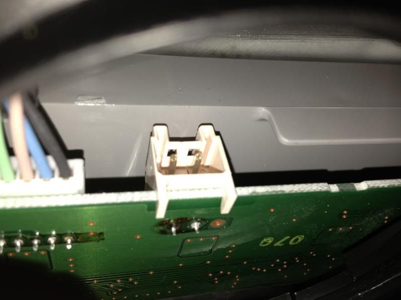
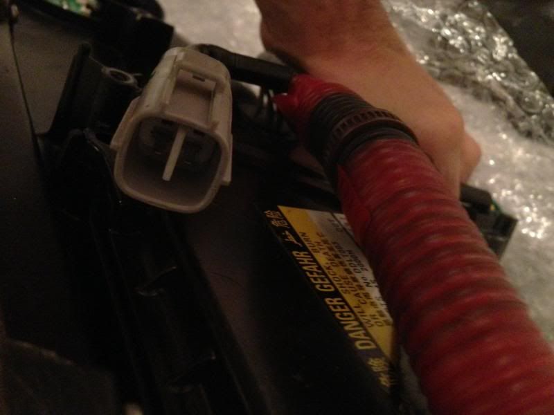
Ive got 201+ led headlights from japan, stripped, so I ordered cords for them. And suprise... they not fit.. This is picture of headlight led connection and other side of the cord:
and cord itself from sewell:
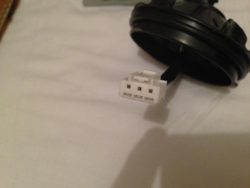
Anyone can explain, whats going on and if is possible show pics of their headlights.. Need help asap, thanks
and cord itself from sewell:
Anyone can explain, whats going on and if is possible show pics of their headlights.. Need help asap, thanks
 08-01-13, 04:26 PM
#4
Intermediate
Something looks wrong on your headlamp bro, it looks like it has been tampered and the connector has been swapped with a 2pin connector instead of the 3pin, coz the 3pin provides, ground, 100% 12V and 50% 12v. i'll post a pic shortly of how it should look
08-01-13, 04:28 PM
#5
Intermediate
Here is a pic of how it should look:
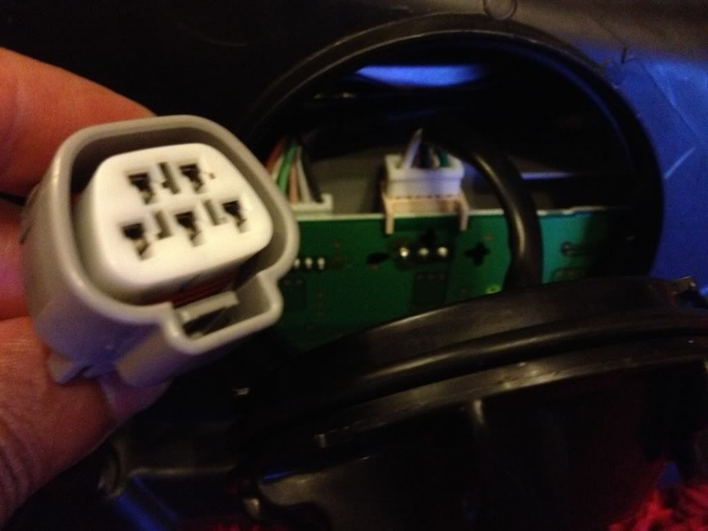
Notice that on your PCB you have one solder point which is removed. The white 5 pin connector on the other hand has two for the turn signal, the turn signal is the row of two pins and the row of 3pins is for the LED lights.
Notice that on your PCB you have one solder point which is removed. The white 5 pin connector on the other hand has two for the turn signal, the turn signal is the row of two pins and the row of 3pins is for the LED lights.
08-01-13, 04:30 PM
#6
Intermediate
You have 3 options:
1. Return to seller because it has been opened and tampered with and may cause problems in the future
2. Just run it on 50% intensity, which is what your pin config can allow.
3. solder all 3 points back on, but i'm assuming it must have been removed for a reason.
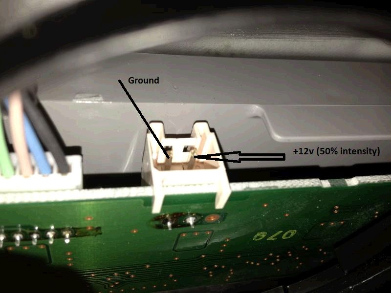
If you want to wire it to work as is with 50% intensity, then heres a pic of the pin configuration, you could simply make a custom crimp plug and plug it in.
1. Return to seller because it has been opened and tampered with and may cause problems in the future
2. Just run it on 50% intensity, which is what your pin config can allow.
3. solder all 3 points back on, but i'm assuming it must have been removed for a reason.
If you want to wire it to work as is with 50% intensity, then heres a pic of the pin configuration, you could simply make a custom crimp plug and plug it in.
Last edited by ahmed24; 08-01-13 at 04:36 PM.
08-01-13, 07:13 PM
#7
You have 3 options:
1. Return to seller because it has been opened and tampered with and may cause problems in the future
2. Just run it on 50% intensity, which is what your pin config can allow.
3. solder all 3 points back on, but i'm assuming it must have been removed for a reason.
If you want to wire it to work as is with 50% intensity, then heres a pic of the pin configuration, you could simply make a custom crimp plug and plug it in.
What I would suggest is to depin the Sewell harness at the circuit board plug and then wrap the pin in heat shrink and connect them to the two pins like mentioned by the above poster.
Trending Topics
08-02-13, 12:19 AM
#8
Lead Lap
Thread Starter
iTrader: (6)
Join Date: Apr 2010
Location: Ireland, Kerry
Posts: 439
Likes: 0
Received 0 Likes
on
0 Posts
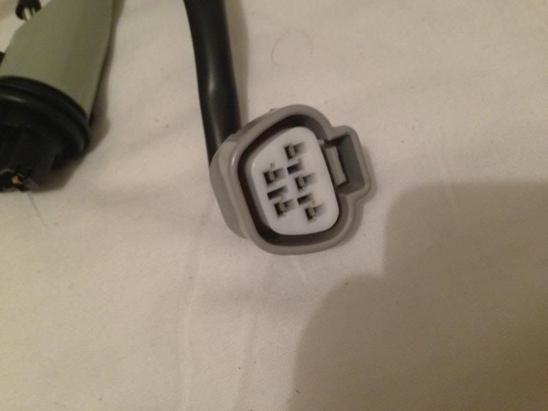
and what about other side - plug is different as well. Also whitch cable I shouldt use? I need 2 and have 3 to the led plug, and from other side there is 4 and harness have 5, so looks like I have one cable more in harness, but whitch one?
Last edited by koksik; 08-02-13 at 12:31 AM.
08-02-13, 05:07 PM
#9
Intermediate
The 2 pins that are soldered on your PCB are ground and the 12V 50% intensity . The middle pin of the 3 pins on the PCB is +12v 50%, the unsoldered pin is the 100% +12V. I dont know why this is but it may be that in Japan they operate it at 50% intensity at all times, or if you purchase this second-hand then maybe its been modified. If you want to simply make it work as it is, you could simple customize the 3 pin connector that you bought from Sewell. Just unpin all 3 pins, and use just the 2 pins and make the 3rd pin redundant.
08-04-13, 06:34 AM
#10
Lead Lap
Thread Starter
iTrader: (6)
Join Date: Apr 2010
Location: Ireland, Kerry
Posts: 439
Likes: 0
Received 0 Likes
on
0 Posts
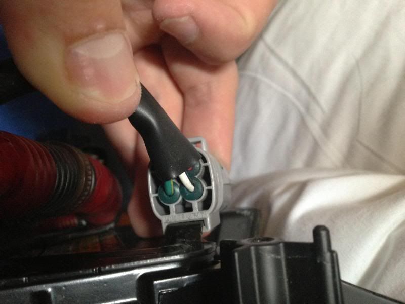
Can anyone share a pic with a plug whitch is in the headlight and u connecting harness. Want to see cables:
Thats a top ( when u turn upside down the headlight:
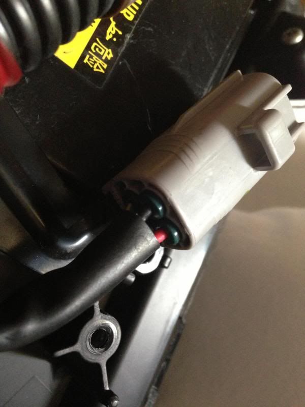
And from bottom: beetwen plug and headlight:
Thats a top ( when u turn upside down the headlight:
And from bottom: beetwen plug and headlight:

Thread
Thread Starter
Forum
Replies
Last Post
jtrinh
IS - 3rd Gen (2014-present)
2
11-06-16 09:06 PM