
sikky o2 simulator
 04-20-12, 06:12 PM
#1
Pole Position
Thread Starter
iTrader: (3)

Join Date: Feb 2011
Location: Texas
Posts: 252
Likes: 0
Received 0 Likes
on
0 Posts
Anybody have the wiring instructions for the microprocessor that comes with sikky headers? I bought the headers from Mitch and he didn't have the instructions. Getting them installed tomorrow and looking for some help. Thanks in advance!
 07-05-12, 04:32 PM
#3
u can try dl and print at sikky.com ? just let you know, the instructor is right but the pic was wrong.
http://www.sikky.com/view_item.php?id=148&catid=15
http://www.sikky.com/view_item.php?id=148&catid=15
07-05-12, 05:55 PM
#4
Haven't read up much about this but most O2 simulators have a similar technique to what Evo guys (and myself) have done which is just a lug extender that moves the sensor out of the test-pipe or other non-cat exhaust path.
I actually didn't know there was a wired chip to deal with for any set of headers.
/subscribing so that I can learn more
I actually didn't know there was a wired chip to deal with for any set of headers.
/subscribing so that I can learn more
 Y'all can thank me in the future with a beer or something.
  07-05-12, 07:05 PM
#6
Lexus Champion
Join Date: Jun 2007
Location: Aventura, Florida
Posts: 2,148
Likes: 0
Received 0 Likes
on
0 Posts
 07-18-12, 09:05 AM
#8
Pit Crew

Join Date: Jan 2012
Location: Alberta
Posts: 247
Likes: 0
Received 0 Likes
on
0 Posts
Followed the instructions, but I'm getting CEL, VSC, traction control light. I double checked yesterday, then reset the ecu, and this morning driving to work CEL came on again. ODBC reader said it was both the downstream o2 sensors. I thought the simulator doesn't even use the signals from the o2 sensors unlike the PPE ones? Do i just have a bad simulator?
Thanks,
J
Thanks,
J

 07-18-12, 10:58 AM
#10
Tech Info Resource

iTrader: (2)
Those vampire taps are notoriously unreliable. There are much better ways to tap wires that don't damage the loom and allow you to restore the wiring to its original OEM condition. They cost a little more, but the wire won't internally corrode over time and end up breaking under the insulation.
07-22-12, 12:14 AM
#12
Pit Crew
Join Date: Jan 2012
Location: Alberta
Posts: 247
Likes: 0
Received 0 Likes
on
0 Posts
So i tripled checked the o2 simulator was wired correctly, but i'm still getting CEL. I tried using a multimeter on the red and black wires on the simulator. 12v when ignition is on, and 13.3v when engine is gone.
07-25-12, 08:56 AM
#14
Pit Crew
Join Date: Jan 2012
Location: Alberta
Posts: 247
Likes: 0
Received 0 Likes
on
0 Posts
I had to set the multi-meter to 200m to get a reading(Connected black wire on multi-meter to black wire on simulator, and the red wire on multi-meter to the yellow wire on multi-meter). With the car running, it gave a constant reading of "02.5". Not sure sure what's the conversion to volts, but maybe that's a bit low?
I'm sure some smart forum members can help . My battery voltage next to the temperature gauge on the cluster seems healthy, dead center.
I'm sure some smart forum members can help
. My battery voltage next to the temperature gauge on the cluster seems healthy, dead center.
07-25-12, 09:24 AM
#15
Tech Info Resource
iTrader: (2)
That's about the ugliest wiring/soldering I've seen in a very long time. How sure are you the connections are good?
A good soldered wire looks like this:
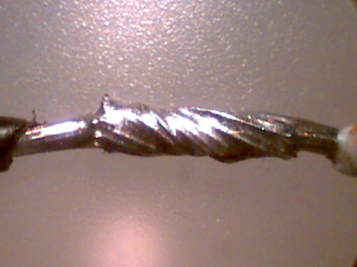
I won't go into why soldering a wiring harness is a horribly bad idea because the horse is already out of the barn and long gone.
If I were you, I'd either fix the connections, or take it to someone who is a competent wiring tech and can solder it properly.
A good soldered wire looks like this:
I won't go into why soldering a wiring harness is a horribly bad idea because the horse is already out of the barn and long gone.
If I were you, I'd either fix the connections, or take it to someone who is a competent wiring tech and can solder it properly.