Is250 Is350 Nav to non nav retrofit camera, mic & voice guidance
 02-20-14, 11:10 PM
#1
Driver School Candidate
Thread Starter
I recently finished a navigation retrofit on my 2007 Lexus Is350. I'd like to start off by giving credit to Club Lexus members Lohus and 350PsDMeuP whom posted the original retrofit information a few years ago. The information I'm posting is to finalize the installation of the factory hands free mic, the factory back up camera, some clarity on the voice guidance, and some additional wires to the navigation unit itself. I have a few detailed pictures from the process. This is my first time publicly posting information like this. My goal with this write up is to give back since I've taken so much knowledge from the Internet.
I am working with is a 2007 is350 and also disassembled a 2006 is250 with nav for comparison purposes. I can not say if other years and models are 100% the same. This information should save alot of time and hassle to those wanting a complete retrofit from Non-Nav to factory Nav. I am using 100% factory parts. I can not assist with any deviation from using factory parts because I honestly don't know what will work, and what won't work. Please be very patient with this, Lexus parts are not cheap and it isn't worth breaking trim pieces.
WARNING- I ASSUME NO RESPONSIBILITY FOR ANY DAMAGES TO YOUR VEHICLE AND/OR YOURSELF. IF YOU DO NOT UNDERSTAND WHAT YOUR READING AND/OR HAVE NO AUTOMOTIVE WIRING EXPERIENCE THEN DO NOT ATTEMPT THIS. TAKE IT TO A LICENSED PROFESSIONAL.
One issue I had from the start was the three connectors on the back of the unit identified as the J50 J51 and J53. From reading the original retrofit thread I figured I would just buy the empty sockets from the dealer, take my dash J54 plug, disassemble it, and pop the original dash wires into the blank new J50, J51, and J53 plugs. This was not the case. The best advice I can give is to buy a unit with these plugs cut from a wrecked vehicle. Pay the extra money because the plugs are a major pain to remove and add wires to. I was not able find the factory wires that lock into the connectors from the dealer. I probably could have if I would have kept digging but the wire colors would be different and would just make the job more complicated.
GPS antenna placement- figure I'll start with the easy stuff. I picked up a factory GPS antenna on eBay for $60. To install the antenna in the factory location, the dash must be removed. Removing the dash is just too much work. If you have a Non Nav car then you most likely have a center speaker grill in your car and it probably doesn't have a speaker underneath. The grill will pop upwards for removal and is the perfect location for the GPS antenna. I removed the factory white plastic mounting bracket from the GPS antenna and then took tin snips and cut down the corners for a snug fit. When removing the grill, use dental picks and a thin plastic wedge to help the process. Remember it's your dash so be careful.
Reverse, VSS (speed sensor) and parking brake signal connections- To have a fully functioning factory Nav retrofit you will need to make these three connections. If you have no interest in a back up camera I believe you can skip the reverse wire. You may be able to skip the parking brake wire as well but I personally did not.
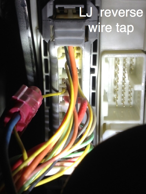
J50 pin 13 Reverse signal can be accessed by tapping into the drivers side junction main connector LJ. It's long, grey and sits just above the fuse box. It's easily accessed by removing the large cover under the steering wheel. It's a yellow wire pin 23
J50 pin 14 pink Speed sensor signal can be acquired just above the glove box assembly from the power module on the J55 connector. Once you have the glove box removed it is mounted to the dash on a bracket. It's a thin blue box and is held in with two 10mm bolts and one 10mm nut. You need to tap the pink wire pin 19
J50 pin 23 Parking brake signal can be accessed at the ABS module. It's on the passenger side just below the glove box. According to my diagrams there are 2 types of ABS modules for this vehicle. With VDIM and without VDIM. Mine is with VDIM and has 3 connectors. You need the J77 connector which is the middle one out of the three. Tap the #14 pin. While the connector is plugged in, looking at the back side of the connector it will be the bottom row, going left to right it's the third wire and should be yellow.

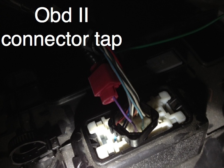
J50 pin 7 violet- this wire should tap into pin 13 on the DLC connector under the dash. Most know it as the OBD II connector under the dash near the brake pedal. I honestly,do not know if this connection is 100% required but I decided to do it.
Passenger airbag detection system- There are two wires you will cut off of your J54 plug that connect to the Srs passenger bulb in the nav unit. For some odd reason, they are missing from the J53 harness. I took my pins out of the Non Nav J54 harness (what a pain) and tried to lock them into the the J53. This was a waste of time. The wire pins are not compatible. In the end, I cut the wires off of the navigation unit side of the harness and connected them to the wires cut from the J54. I used red female and male spade connectors incase I ever need to remove the unit. The wires are very small so they aren't very disconnect friendly, however this will keep your SRS system light off
Hands free mic removal and placement- The hands free mic is located in the domelight/sunroof switch. Its a small rectangular black piece that snaps in towards the rear left of the assembly. To remove the unit, open the sunglasses storage compartment. You will see two small square access covers. Pop each one off with your dental pick. You will now have access to two philips screws. Remove the screws. Towards the rear of the unit there are two door panel type clips holding the assembly to the roof. I like to use a squeeze type door panel clip removal tool but you can just pull straight down on the unit with your hands. If the clips stay in the roof, you will need to remove them from the roof when you reinstall the unit. The domelight assembly will have two empty rectangle holes towards the rear of the unit. (rear meaning closest to the actual glass sunroof). The mic will snap into the one closest to the drivers seat and you will see a small white socket for the mic to plug into. You will probably want to just buy a complete domelight/sunroof switch unit off of eBay they cost about $100 but be sure to look closely at the pictures to ensure the mic is there. It's easy to identify because it always has a factory piece of Velcro type tape over it. You can also obviously see that one removed from a non-nav vehicle will have two empty rectangular holes. This is not what you are looking for.
Hands free mic wiring and connection- Once you have the domelight unit mic installed, you will then need to connect it to the J51 on the back of the unit. The dome light harness on the vehicle I was working on had the mic wires in the harness. The wires run to the JR2/JR1 connector. I can not identify which connector is the JR2 and which is the JR1, the schematic shows the mic wires in the JR1. They are located in the drivers side windshield pillar. To remove the pillar trim is a pain because of the side curtain airbag. I decided to not remove the airbag but removing it is the correct and clean way to do this next step. On the pillar over, towards the roof where it says "Srs air bag" there is a leg of the trim panel that is not removable without removing the complete left curtain airbag. Further down towards the dash there is a clip (door panel type like the domelight) that can be removed to give you access to the JR1/JR2 connectors. I pryed up on this area and pulled out the door rubber black weather seal along the door jamb to gain access to both connectors. Once you have access you will see the two connectors. One has a harness connected to it from the dash side, the other does not. The one without anything plugged into it is the one you want. It should have 4 wires in it. The brown, white and yellow are the wires you need. Cut the connector off and crimp a wire to each wire extending it to reach the headunit J51 plug. Originally I extended all 4 wires but after some trial runs and factory wire schematics, I realized the black taped wire was not necessary and is just a shielding to reduce interference.
J51 brown pin 10
J51 yellow pin 11
J51 violet pin 9 NOTE- @ the JR2 this wire will be white. So it goes white to violet at the head unit
On the J51 itself connect pin 5 to pin 12 they are white with black stripe. Basically it's just a loop. I have no idea why but the mic would not work unless these two wires are connected. The schematic shows the wires looped together
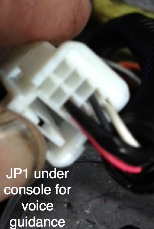
Voice guidance- in the original nav retro fit supplement addition thread, it explained how to connect the voice guidance from the factory amp. My mistake was that I didn't realize on the amp plug J30, the pin 15 and 14 colors did not match the colors that come off the J51. With this misinformation I decided to run my own wires from the dash to the trunk. This was a huge waste of time. My wires on the J30 are green and white and at the J51, they are yellow and brown. If your J30 has these wires, no matter what the color is then you do not need to run wires from the head unit to trunk. You simply need to remove the center console and locate the JP1 harness connector. it sits just in front of the SRS module which is directly below the console storage compartment. You will see the connector with a harness plugging into it from the dash side. Look closely and you will see there are 3 wires missing from the connector coming from the dash. These are the wires you will need to access. The colors should now match those coming off of the J51 connector. You need to cut these wires off the connector and again crimp and extended them to reach the J51.
J51 brown pin 21
J51 yellow pin 22
J51 black taped pin 23
Back up camera wiring- Like the voice guidance, I learned the hard way that the vehicle was pre wired all the way to the center console. Once you remove the trunk trim panel, you should be able to see the camera connector. This connector is factory wired all the way to the JQ3 connector located in the center console area. This connector will be located on the drivers side near the JP1 connector mentioned in the voice guidance section above. It's a ten wire plug. If you look closely again like the JP1 you will see wires on the rear side connector that are not located in the front side (dash) connector . There are four wires to be exact. Again cut the four wires (white, black, red and black with a thin tape look) off the connector and crimp them to new wires to extended them to the J51 wires .
J51 white pin 14
J51 black pin 13
J51 red pin 27
J51 black taped pin 28
WARNING the other wires on the connector are similar in color so be 100% sure you are cutting the wires that do not come out of the mating harness.

Physical camera install-You will need to remove the tail panel trim to cut it and the metal portion of the trunk out to fit your camera. I'm not much of a fabricator so this was my least favorite part of the install. The outer tail panel trim will have two thin raised outline squares for the camera cut out. This will make your job much easier. Realize, this is the facia. It will be the part seen by you everyday you gloat over the great installation job you've done so take your time. I used a dremel with a cut off wheel and used the outer raised square mark as a guide The nav type tail panel comes with a rubber boot to protect and cover the cut out area but at this time, I have been unable to find the correct part number for this piece. The second cut you need to make is In the metal trunk portion. I had disassembled another Is250 that had a factory Nav system. I removed its camera and made a cardboard template. The problem is the cut needs to be precise because the factory camera mount holes are not useable for mounting. You will need to use the two snap tabs on the camera itself. On a vehicle with Nav there are two welded nuts to the trunk metal. Non Nav cars do not have these. Originally I drilled the holes and thought id just put nuts on and hand tighten them. Great idea! unfortunately its will not work because the tail panel trim will not remount to the car with the camera in place. The camera must be installed after the tailpanel is mounted. You could weld some nuts in place if you're handy with a welder. Personally I have zero welding experience and in my opinion the factory tabs hold the unit in place just fine.
I am working with is a 2007 is350 and also disassembled a 2006 is250 with nav for comparison purposes. I can not say if other years and models are 100% the same. This information should save alot of time and hassle to those wanting a complete retrofit from Non-Nav to factory Nav. I am using 100% factory parts. I can not assist with any deviation from using factory parts because I honestly don't know what will work, and what won't work. Please be very patient with this, Lexus parts are not cheap and it isn't worth breaking trim pieces.
WARNING- I ASSUME NO RESPONSIBILITY FOR ANY DAMAGES TO YOUR VEHICLE AND/OR YOURSELF. IF YOU DO NOT UNDERSTAND WHAT YOUR READING AND/OR HAVE NO AUTOMOTIVE WIRING EXPERIENCE THEN DO NOT ATTEMPT THIS. TAKE IT TO A LICENSED PROFESSIONAL.
One issue I had from the start was the three connectors on the back of the unit identified as the J50 J51 and J53. From reading the original retrofit thread I figured I would just buy the empty sockets from the dealer, take my dash J54 plug, disassemble it, and pop the original dash wires into the blank new J50, J51, and J53 plugs. This was not the case. The best advice I can give is to buy a unit with these plugs cut from a wrecked vehicle. Pay the extra money because the plugs are a major pain to remove and add wires to. I was not able find the factory wires that lock into the connectors from the dealer. I probably could have if I would have kept digging but the wire colors would be different and would just make the job more complicated.
GPS antenna placement- figure I'll start with the easy stuff. I picked up a factory GPS antenna on eBay for $60. To install the antenna in the factory location, the dash must be removed. Removing the dash is just too much work. If you have a Non Nav car then you most likely have a center speaker grill in your car and it probably doesn't have a speaker underneath. The grill will pop upwards for removal and is the perfect location for the GPS antenna. I removed the factory white plastic mounting bracket from the GPS antenna and then took tin snips and cut down the corners for a snug fit. When removing the grill, use dental picks and a thin plastic wedge to help the process. Remember it's your dash so be careful.
Reverse, VSS (speed sensor) and parking brake signal connections- To have a fully functioning factory Nav retrofit you will need to make these three connections. If you have no interest in a back up camera I believe you can skip the reverse wire. You may be able to skip the parking brake wire as well but I personally did not.
J50 pin 13 Reverse signal can be accessed by tapping into the drivers side junction main connector LJ. It's long, grey and sits just above the fuse box. It's easily accessed by removing the large cover under the steering wheel. It's a yellow wire pin 23

J50 pin 14 pink Speed sensor signal can be acquired just above the glove box assembly from the power module on the J55 connector. Once you have the glove box removed it is mounted to the dash on a bracket. It's a thin blue box and is held in with two 10mm bolts and one 10mm nut. You need to tap the pink wire pin 19
J50 pin 23 Parking brake signal can be accessed at the ABS module. It's on the passenger side just below the glove box. According to my diagrams there are 2 types of ABS modules for this vehicle. With VDIM and without VDIM. Mine is with VDIM and has 3 connectors. You need the J77 connector which is the middle one out of the three. Tap the #14 pin. While the connector is plugged in, looking at the back side of the connector it will be the bottom row, going left to right it's the third wire and should be yellow.

J50 pin 7 violet- this wire should tap into pin 13 on the DLC connector under the dash. Most know it as the OBD II connector under the dash near the brake pedal. I honestly,do not know if this connection is 100% required but I decided to do it.

Passenger airbag detection system- There are two wires you will cut off of your J54 plug that connect to the Srs passenger bulb in the nav unit. For some odd reason, they are missing from the J53 harness. I took my pins out of the Non Nav J54 harness (what a pain) and tried to lock them into the the J53. This was a waste of time. The wire pins are not compatible. In the end, I cut the wires off of the navigation unit side of the harness and connected them to the wires cut from the J54. I used red female and male spade connectors incase I ever need to remove the unit. The wires are very small so they aren't very disconnect friendly, however this will keep your SRS system light off
Hands free mic removal and placement- The hands free mic is located in the domelight/sunroof switch. Its a small rectangular black piece that snaps in towards the rear left of the assembly. To remove the unit, open the sunglasses storage compartment. You will see two small square access covers. Pop each one off with your dental pick. You will now have access to two philips screws. Remove the screws. Towards the rear of the unit there are two door panel type clips holding the assembly to the roof. I like to use a squeeze type door panel clip removal tool but you can just pull straight down on the unit with your hands. If the clips stay in the roof, you will need to remove them from the roof when you reinstall the unit. The domelight assembly will have two empty rectangle holes towards the rear of the unit. (rear meaning closest to the actual glass sunroof). The mic will snap into the one closest to the drivers seat and you will see a small white socket for the mic to plug into. You will probably want to just buy a complete domelight/sunroof switch unit off of eBay they cost about $100 but be sure to look closely at the pictures to ensure the mic is there. It's easy to identify because it always has a factory piece of Velcro type tape over it. You can also obviously see that one removed from a non-nav vehicle will have two empty rectangular holes. This is not what you are looking for.
Hands free mic wiring and connection- Once you have the domelight unit mic installed, you will then need to connect it to the J51 on the back of the unit. The dome light harness on the vehicle I was working on had the mic wires in the harness. The wires run to the JR2/JR1 connector. I can not identify which connector is the JR2 and which is the JR1, the schematic shows the mic wires in the JR1. They are located in the drivers side windshield pillar. To remove the pillar trim is a pain because of the side curtain airbag. I decided to not remove the airbag but removing it is the correct and clean way to do this next step. On the pillar over, towards the roof where it says "Srs air bag" there is a leg of the trim panel that is not removable without removing the complete left curtain airbag. Further down towards the dash there is a clip (door panel type like the domelight) that can be removed to give you access to the JR1/JR2 connectors. I pryed up on this area and pulled out the door rubber black weather seal along the door jamb to gain access to both connectors. Once you have access you will see the two connectors. One has a harness connected to it from the dash side, the other does not. The one without anything plugged into it is the one you want. It should have 4 wires in it. The brown, white and yellow are the wires you need. Cut the connector off and crimp a wire to each wire extending it to reach the headunit J51 plug. Originally I extended all 4 wires but after some trial runs and factory wire schematics, I realized the black taped wire was not necessary and is just a shielding to reduce interference.
J51 brown pin 10
J51 yellow pin 11
J51 violet pin 9 NOTE- @ the JR2 this wire will be white. So it goes white to violet at the head unit
On the J51 itself connect pin 5 to pin 12 they are white with black stripe. Basically it's just a loop. I have no idea why but the mic would not work unless these two wires are connected. The schematic shows the wires looped together
Voice guidance- in the original nav retro fit supplement addition thread, it explained how to connect the voice guidance from the factory amp. My mistake was that I didn't realize on the amp plug J30, the pin 15 and 14 colors did not match the colors that come off the J51. With this misinformation I decided to run my own wires from the dash to the trunk. This was a huge waste of time. My wires on the J30 are green and white and at the J51, they are yellow and brown. If your J30 has these wires, no matter what the color is then you do not need to run wires from the head unit to trunk. You simply need to remove the center console and locate the JP1 harness connector. it sits just in front of the SRS module which is directly below the console storage compartment. You will see the connector with a harness plugging into it from the dash side. Look closely and you will see there are 3 wires missing from the connector coming from the dash. These are the wires you will need to access. The colors should now match those coming off of the J51 connector. You need to cut these wires off the connector and again crimp and extended them to reach the J51.
J51 brown pin 21
J51 yellow pin 22
J51 black taped pin 23

Back up camera wiring- Like the voice guidance, I learned the hard way that the vehicle was pre wired all the way to the center console. Once you remove the trunk trim panel, you should be able to see the camera connector. This connector is factory wired all the way to the JQ3 connector located in the center console area. This connector will be located on the drivers side near the JP1 connector mentioned in the voice guidance section above. It's a ten wire plug. If you look closely again like the JP1 you will see wires on the rear side connector that are not located in the front side (dash) connector . There are four wires to be exact. Again cut the four wires (white, black, red and black with a thin tape look) off the connector and crimp them to new wires to extended them to the J51 wires .
J51 white pin 14
J51 black pin 13
J51 red pin 27
J51 black taped pin 28
WARNING the other wires on the connector are similar in color so be 100% sure you are cutting the wires that do not come out of the mating harness.

Physical camera install-You will need to remove the tail panel trim to cut it and the metal portion of the trunk out to fit your camera. I'm not much of a fabricator so this was my least favorite part of the install. The outer tail panel trim will have two thin raised outline squares for the camera cut out. This will make your job much easier. Realize, this is the facia. It will be the part seen by you everyday you gloat over the great installation job you've done so take your time. I used a dremel with a cut off wheel and used the outer raised square mark as a guide The nav type tail panel comes with a rubber boot to protect and cover the cut out area but at this time, I have been unable to find the correct part number for this piece. The second cut you need to make is In the metal trunk portion. I had disassembled another Is250 that had a factory Nav system. I removed its camera and made a cardboard template. The problem is the cut needs to be precise because the factory camera mount holes are not useable for mounting. You will need to use the two snap tabs on the camera itself. On a vehicle with Nav there are two welded nuts to the trunk metal. Non Nav cars do not have these. Originally I drilled the holes and thought id just put nuts on and hand tighten them. Great idea! unfortunately its will not work because the tail panel trim will not remount to the car with the camera in place. The camera must be installed after the tailpanel is mounted. You could weld some nuts in place if you're handy with a welder. Personally I have zero welding experience and in my opinion the factory tabs hold the unit in place just fine.
 02-18-17, 09:28 AM
#2
Driver School Candidate
I know it almost three years later but this was huge for finding this info doing a nav in 2012 with 2011 IS 350 nave unit with all the connectors except for on and that is the high speed video wire with light blue connector to white 4 pin connector that no one can seem to find yet alone the correct part number for it
Thanks again
Thanks again
The following users liked this post:
Jrod5150 (01-12-21)

Thread
Thread Starter
Forum
Replies
Last Post
Solara350
IS - 3rd Gen (2014-present)
0
03-25-17 07:55 AM
ISMAN1000
Lexus Audio, Video, Security & Electronics
1
07-08-09 01:02 PM

