When you click on links to various merchants on this site and make a purchase, this can result in this site earning a commission. Affiliate programs and affiliations include, but are not limited to, the eBay Partner Network.
I was disappointed that my GX didn’t have any power outlets for the back seat occupants, so I fixed that issue. For flexibility with different devices, I set out to add a 12v socket, and a USB socket with two, 2A plugs. Two sockets would give more charging options, less fighting in the back seat, and also maintain a symmetrical look on the back of the console. Note that I have the base model, which includes two HVAC vents on the back of the console. I do not have the rear AC controls and don't know how that changes what is behind the rear console cover.
Here’s the process I went through to add 12v accessory power in my 2013 GX.
Note: Messing around with 12v electronics can be risky. Disconnect the battery to reduce the risk of getting electrocuted. If you want to give upgrade this a shot in your GX, I encourage you to do so. But if you mess it up, I won't be held accountable for your mistakes.
__________________
- Matt
2013 GX 460
1996 FZJ80
1976 FJ40
Last edited by Jacket; 04-20-15 at 11:10 AM.
Reason: disclaimer
I sourced the outlets from Waytek Wire. Waytek will kill you with shipping charges, so buyer beware. But they do have a strong catalog of electrical supplies.
First, remove the back panel from the center console storage box. It’s held in by 8 clips. Best to start at the bottom and work your way toward the top. If you have a plastic trim tool, it is helpful to wedge the tool into the seam near the floor carpet, and twist slightly until the clip pops free. Do the same thing on both sides. Don’t pull two hard, as there are a couple of wire harnesses to unplug (maybe more depending on what trim packages you have).
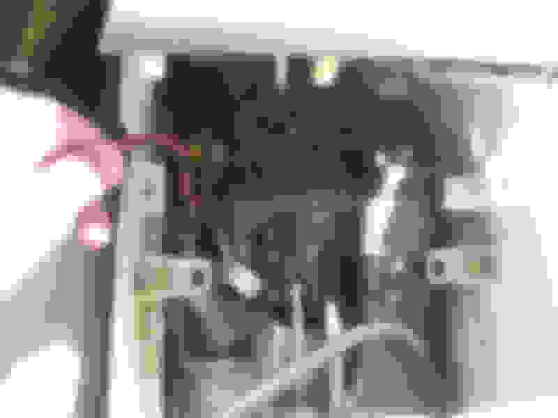
I’m not sure about all models, but for mine I had the HVAC duct running right up the middle of the space behind the console cover. It’s about 4” wide and leaves little room to add anything with any depth. I found a spot on each side of the duct between the 2nd and 3rd clips (counting up from the bottom. It’s about 3” of depth, and the outlets I bought needed about 2.5”.
(Ignore the new wires here as I forgot to take a “before” picture). The red arrows indicate the general area where the sockets will be, as this area had the most depth.
I measured on the back side of the console panel to find a spot that both cleared the duct (needed 4” of clearance from the center), and also would not interfere with a plastic clip used to attach the wire harness for the rear HVAC. There was just enough room for the 29mm (1 1/8”) hole on the driver’s side, and a matching hole on the passenger side. I marked the center of the circle I would make, and drilled a pilot hole from the inside to ensure I located the hole in the right spot. I’m not sure what this replacement panel costs with Lexus, but I was hoping I got my measurements right…. Make sure to run the drill/hole saw very slowly so that you don’t burn or melt the plastic. As long as you are seeing plastic shavings coming out from the hole saw, you are doing it slow enough.
Last edited by Jacket; 12-13-15 at 08:07 AM.
Reason: fixed links
There are two spots I found in the interior fuse panel where power is supplied but the slot is unfused and unlabeled. The slot between the 20A washer circuit and the 10A Cooling circuit is empty on my GX, and supplied with power upon ignition. Perfect for what I need.
I picked up one of these add-a-circuit fuses to drop into the empty slot for the power supply. Toyota uses the low profile mini fuses, which are a bit harder to find but generally available.
(sorry for the bad picture) I ran the grounding wires to the bolt that secures the fuse box to the body.
In order to hide the wiring, it is necessary to pull up sections of the center console. Start with the leather side garnishes. They are held in by clips. Start at the rear, and again, if you have a plastic trim tool that you can wedge between the side piece it helps to get it started. Once you pop the first clip free, you can gently but firmly pop the remaining clips free. Do this on both sides.
Next is to open up the trim piece around the AT shift lever. Same deal – held in by clips. First – unscrew the shifter ****. Pull up from the rear at each corner until the back clips pop free. There are a bunch of wire harnesses attached to this piece, and so I didn’t bother to completely remove it. I just needed enough space to fish through some wires.
Once the back of the shifter piece is free, you can then remove the cup holder. Gently pull straight up on the sides of the cup holder to pop the clips free. There is a wire harness for the LED light that you’ll need to unplug in order to remove the cup holder.
It is not necessary to completely remove the storage console, but I loosened it to help with access to fish the wires. There are two bolts at the bottom of the box, and then Phillips head screws on the sides and back.
Once you get the shifter surround and cup holder plastic up and out of the way, it becomes fairly obvious where you can create a path to feed some new wires from the back to the front.
At this point there is enough room to fish wires through the center channel. Since I’m adding two power sockets, I went ahead and made a wire bundle with two reds and two blacks, and wrapped it in �” corrugated loom.
Starting at the back of the console, I fed the wires around the HVAC duct, and along the bottom of the passenger side of the console box. At the front of the console box I crossed over the wire bundle to the drivers side, and then along the drivers side edge of the console past the AT shifter and up to the drivers foot well. With the cup holder out of the way, and the shifter assembly plastic raised, the wires can be easily fed toward the front through the large passages that exist.
Under the steering column, there is a black plastic cover shielding the wires and pedal assemblies, so I dropped that down for access. It is held in place via a single Phillips head screw under the steering column, and a couple of clips on each side. Once the plastic cover is dropped, you need to unclip the map plug and another unused wire harness, and then you can set the plastic cover aside.
From here, the wires go up and over the pedal assemblies, and then down to the driver side kick panel where the fuse box is located. I spliced the power wires for the two new sockets into the add-a-fuse. The 12V socket is rated at 15 amps max, although it’s unlikely we’ll ever come close to that for my needs. I went ahead and put a 20A fuse into the add-a-circuit fuse holder in case we are drawing full amperage from both the 12v socket and the two USB sockets (2A each). At this point, you are done wiring.
Back at the socket end, I used right angle connectors to minimize the protrusion of the plugs on the back of the sockets, knowing the clearances were tight.
Plug these female connectors into the back of the spade terminals on the sockets, and test the system. Once the power supply is confirmed, secure the wiring with zip ties, reassemble all the console pieces, and enjoy.
Nice job. I need to wire my new dash camera into the fuse box and plan on going to the main fuse box under the hood, by the engine. My reasoning is the main fuse box has more room for the "add a circuit". I dont think you were able to reinstall the cover that shows the fuse diagram, correct? If it is lost or misplaced it could be a hassle to determine the location of the fuses.
Possibly, but it's no hassle to zip tie the cover near the fuse box for future reference and so it doesn't go missing. Or put it in the glove box. And of course the owners manual details all the fuses as well.
The engine fuse box would work as well, but then you'll have to fish the wires through the firewall. Always tradeoffs....
__________________
- Matt
2013 GX 460
1996 FZJ80
1976 FJ40
Last edited by Jacket; 04-30-15 at 02:04 PM.
Reason: spelling
Incredible detailed work! I was going to install a 12V & USB also but was concerned about spending hours figuring out how to take it apart. You eliminated my concern. Thanks for posting and showing your work of art!
Converting 12V DC power in your vehicle to 120V (via an inverter), and then back to the low voltage of a handheld device is pretty inefficient with most of the inverters used these days. That's not the route I'd go.
 04-13-15, 01:20 PM