When you click on links to various merchants on this site and make a purchase, this can result in this site earning a commission. Affiliate programs and affiliations include, but are not limited to, the eBay Partner Network.
Hi guys. I've just been working on this mod but realised my pot meter is 500k! I'm guessing this is far too high as most people run a 10k. I don't know much about pot meters, could someone advise if the one I have is any use?
Here is how I did this mod, based on all of the information posted in this thread. I bought an ECU off eBay, and modified it, replacing the ECU in the car (which I wanted to keep untouched, in case I bricked it doing this mod!).
As others have said, this may be the best bang for your buck mod for the 2GS. With this modified steering ECU, I'm finally satisfied with the corrected power steering effort. The wheel is now easier to turn at all speeds, and it feels right.
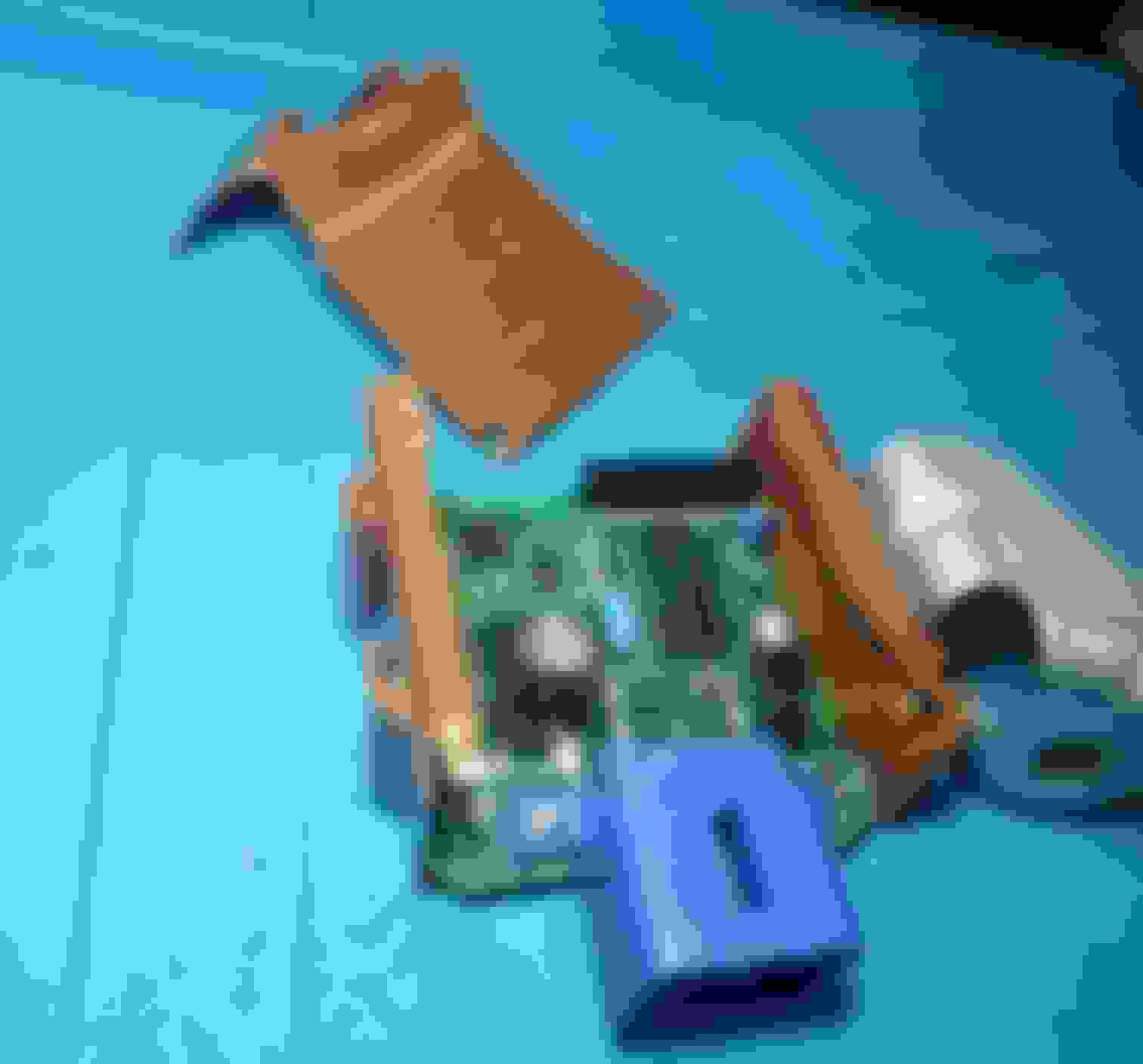
The PCB is locked into the case firmly with sharp detents. I had to cut the cover off to remove the PCB. With the cover removed, flex the case walls outward, and the tension is released from the PCB, allowing it to easily slide out. I later hot glued the cover back on, and wire tied my variable potentiometer wires to the blue connector housing.
Measuring the resistance of R1 (the resistor that will be replaced with the variable potentiometer), it reads 4k ohm. A 10k pot seems appropriate, at %250 of the nominal R1 resistance.
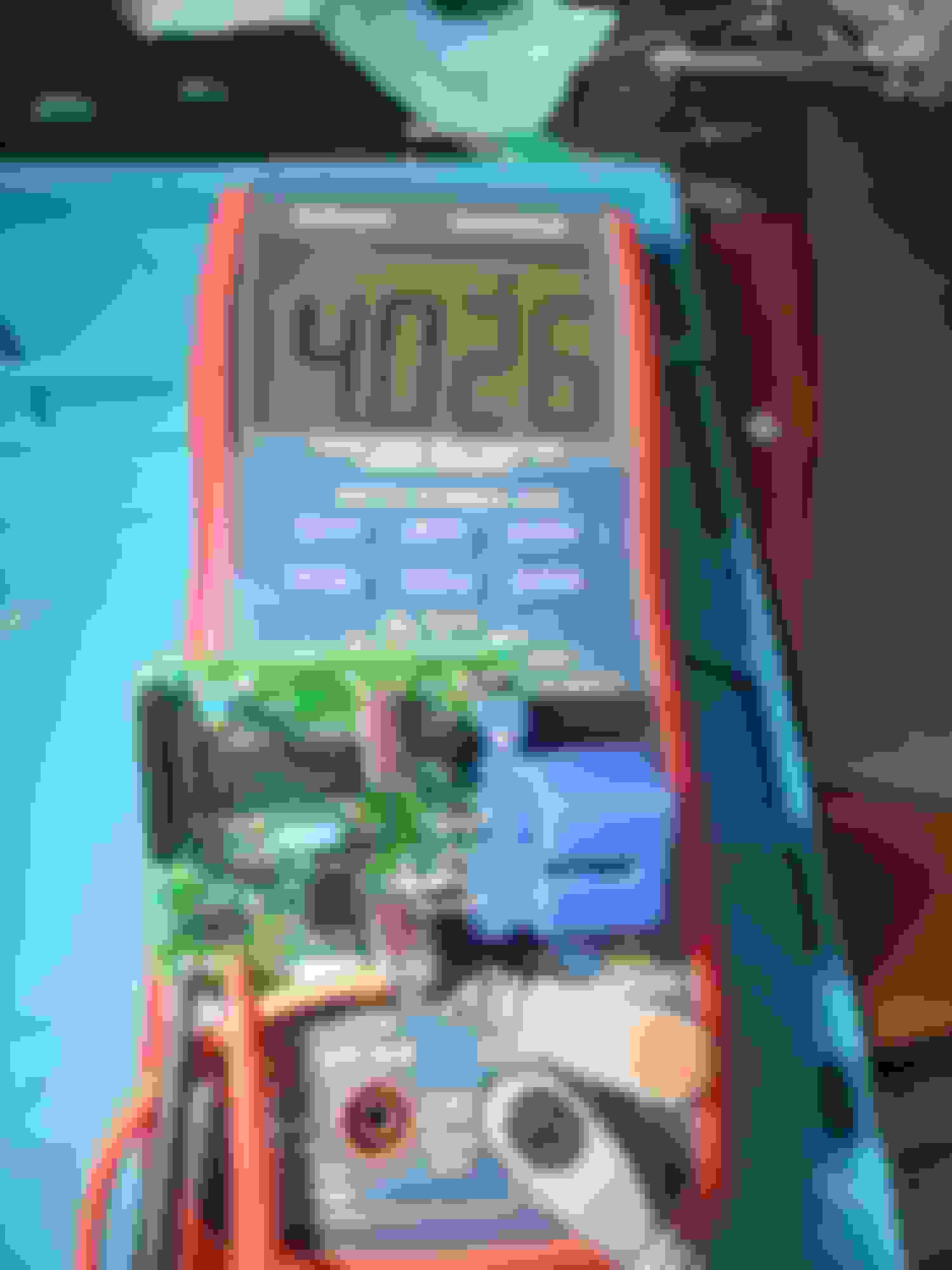
Measuring the resistance of the variable potentiometer, you can see how the far left (CCW) value is almost zero ohms (1.8 ohms), about 11 o'clock is the factory resistance value (4k ohms), and full right (CW) gives about 10k ohms.
Next, I de-soldered the tiny resistor from the PCB, which was more difficult than I thought, because the resistor wires are bent behind the PCB. It is easier to first snip the bent legs on the back of the PCB, then touch each leg with a soldering iron and push the leg out the front of the PCB. Once the tiny resistor finally falls off the PCB, it can be discarded.
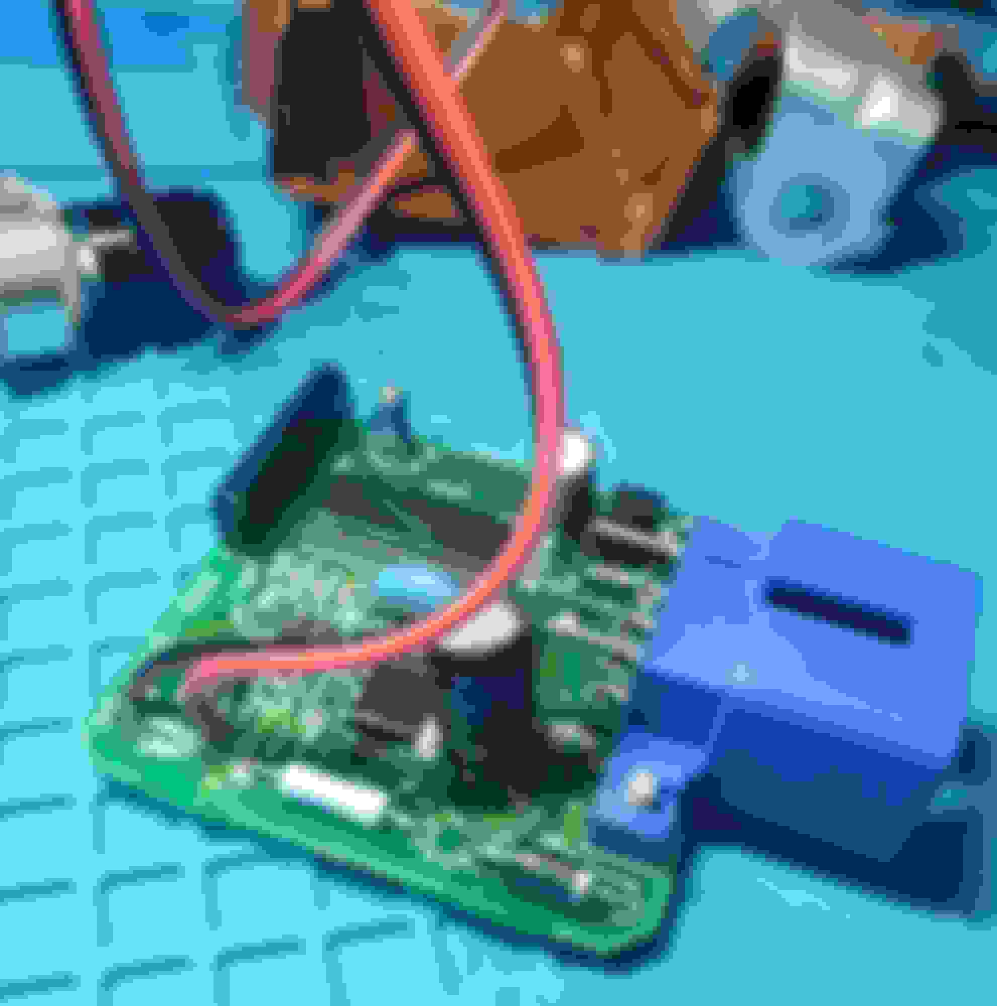
Carefully soldered extension wires onto the resistor pads (thru holes). These wires go to the variable potentiometer, mounted below the steering wheel. I used 18 gauge wire, which was overkill. I had to trim about half of the wires to fit each bundle into the tiny holes. The other end of the wires were soldered to the (remote) variable potentiometer.
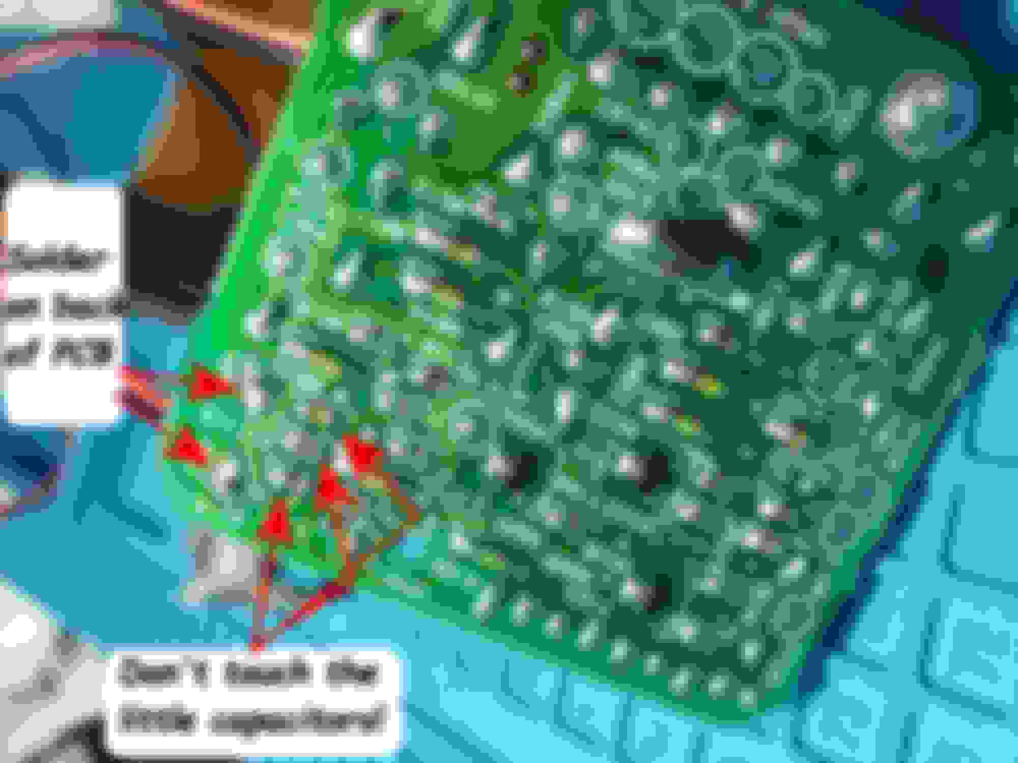
When de-soldering the R1 resistor from the back side, make sure you don't fry the tiny capacitors next to the resistor pads! The photo shows the variable potentiometer extension wires soldered into the resistor holes. Remember to clean your PCB after soldering (isopropol alcohol works great) to remove the corrosive flux!
With the eBay ECU modified, I then had to locate my steering ECU, which the red arrow points to. I had to remove the lower black under-cover (2 screws, 1 pull clip) to access the ECU. The picture was taken from below the dash, in the driver's side footwell, looking upward.
I then removed the 3 bolts from the "tan" panel. I could then flex it enough to stick a long socket extension through the gap, to remove the steering ECU bolt (and to later re-torque it). You don't need to remove the steering column cover, unless you want to stare at your burnt out steering column motors. I replaced mine, and programmed them to not auto-stow when the ignition turns on, so that the replacement motors don't burn out. I digress. Also, I couldn't find the 4th (or 5th?) bolts that hold this panel in place, in order to fully remove it. There must be another bolt somewhere near the steering column, as this is where the panel will not detach.
Looking through the gap that I stuck the socket extension through, the steering ECU can be seen, with the 10mm socket on the bolt. You'll still need to access the ECU and bolt from below, but torquing the bolt is easier from this gap.
After swapping in the modified ECU, I then mounted the pot **** here. After drilling the through hole, I had to cut away the front face vinyl/pad (counterbore it), in order to get the nut on the pot stem (the panel is thicker than the pot was designed for). I used a 1/2" diameter steel hole punch to remove the material, making sure to hold it concentric to the hole, so the removed face material didn't show. I spun the hole punch while pushing on the front face until it cut through the face material. I also almost located the through hole too close to a rib that is behind the panel. Any close, and I would have had to cut away the rib.
If I had to do it over again, I would have tried a 20k or 50k potentiometer. I keep the **** turned full right (CW, 10k ohms), which increases the power steering effort just enough for me to finally enjoy the steering on my 2GS. I would probably appreciate even more steering assist with a higher resistance pot. And yes, turning the pot to 12 o'clock sets the power steering back to factory, and turn the **** full left (CCW, ~0 ohms) makes the steering very heavy.
 02-11-15, 11:32 AM