DIY GS300 coil pack connectors
 04-10-11, 12:56 AM
#1

I was having random misfires on my 98 2GS300 and found that the coil pak connectors had disintegrated because of the heat.
I did a quick search and didn't see a DIY for the coil pack connector replacement, so I thought I would post one up on here. I am new to this forum and want to be a contributing member here. here is a picture of the part number.

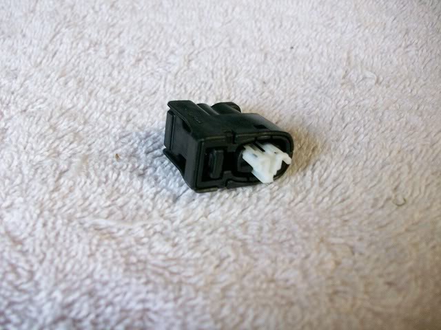
here is a picture of the new connector. Be sure not to push in the white portion of the connector, that is done last in the building of the connector.
I got all three connectors from my local Toyota dealership for 22 bucks total for all of them. That part number 90980-11246 is a Lexus or Toyota part number.
Without further ado, off to the work.
Tools needed are:
1. Metric allen wrench set
2. 12mm deep socket
3. 3 inch extension
4. Ratchet wrench
5. Pliers, regular and needle nose
6. 14mm Combination wrench
7. #3 phillips srewdriver
1. Remove the negative terminal from the battery. (no Picture needed)
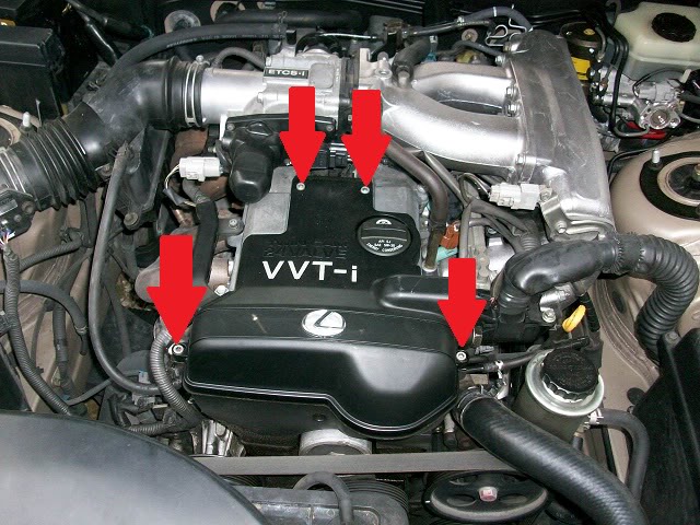
2. Remove 4 allen bolts that hold on the timing gear cover
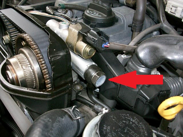
3. (optional) While the engine cover is off, you can take off this bolt and clean the OCV filter. This is not required though. The filter is behind the bolt with the arrow pointing to it.
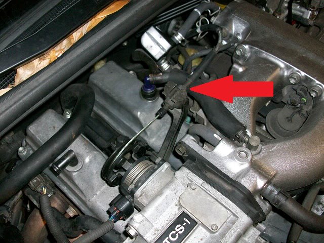
4. Pull this connector off the throttle body.
5. Loosen these 2 screws on the intake tube marked with red arrow, and remove the hoses indicated by the green arrows.
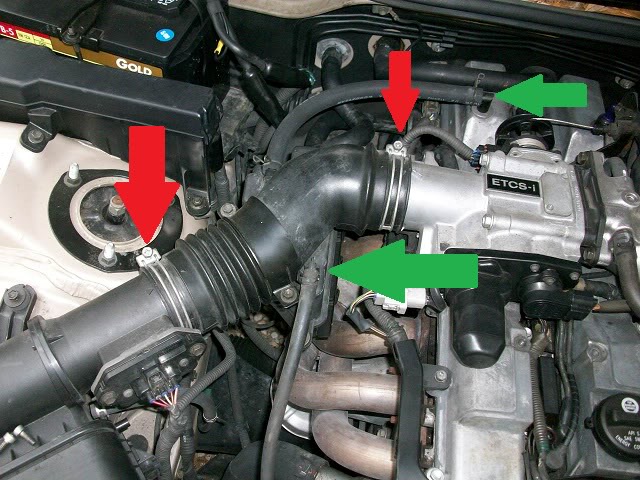
6. Loosen this nut on the throttle cable, and pull the throttle cable out of the bracket. Remove the throttle cable end out of the throttle body
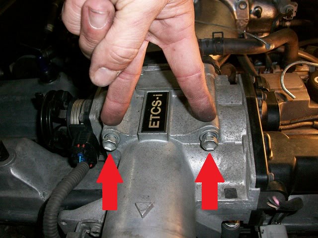
7. Remove these 5 nuts that are indicated by the red arrows. The two on the bottom are hidden by the wiring harness in the picture, but can easily be seen.
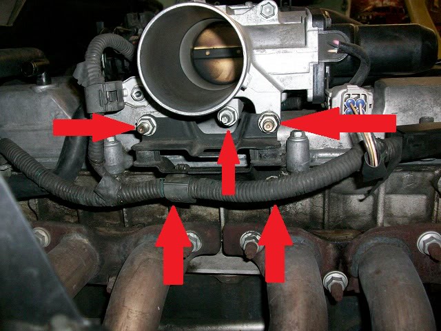
8. Remove the two bolts at the top of the throttle body.
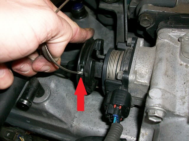
9. Remove this hose off the throttle body.
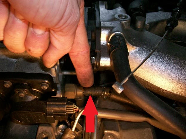
10. At this time, the throttle body can be moved. I just pulled it out far enough to where i could get to the connector.
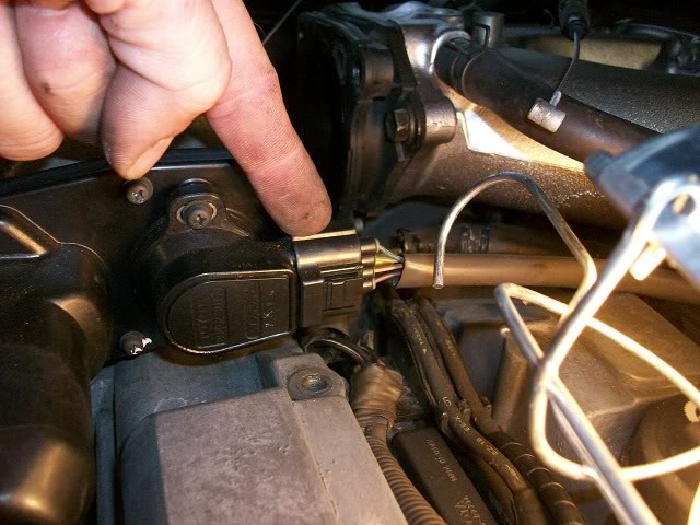
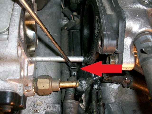
11. This is the connector that I am replacing at this time. you can see from the picture, that all that is inside the connector is two female pins. They were able to just float around.
12. I don't have any pics of this, but it is very easy. since there was nothing on the inside of my old connector, the wires just pulled right out. be sure to note which way the wires were placed in the connector, beause they will have to go back the same way. When I did my other ones, there was still some plastic still inside the connector, and all I had to do was take a small screwdriver, and break all the left over pieces out from around the pins.
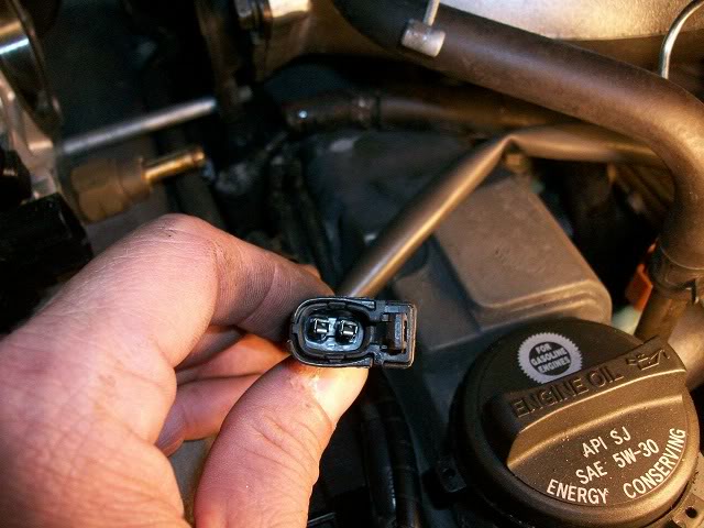
13. To assemble the new connectors, push in the female pins from the back of the connector until they click into place. Be sure to put them back in the same orientation that they came out. once the pins are in the connector, push in the white piece until it clicks into place. your pins are now secure in the connector. This is what it will look like after.

14. I would suggest replacing the other two while you're in the process, if one broke, the others probably aren't far behind.
15. Installation is the reverse of disassembly.
Hope this DIY may help someone down the road.
I did a quick search and didn't see a DIY for the coil pack connector replacement, so I thought I would post one up on here. I am new to this forum and want to be a contributing member here. here is a picture of the part number.
here is a picture of the new connector. Be sure not to push in the white portion of the connector, that is done last in the building of the connector.
I got all three connectors from my local Toyota dealership for 22 bucks total for all of them. That part number 90980-11246 is a Lexus or Toyota part number.
Without further ado, off to the work.
Tools needed are:
1. Metric allen wrench set
2. 12mm deep socket
3. 3 inch extension
4. Ratchet wrench
5. Pliers, regular and needle nose
6. 14mm Combination wrench
7. #3 phillips srewdriver
1. Remove the negative terminal from the battery. (no Picture needed)
2. Remove 4 allen bolts that hold on the timing gear cover
3. (optional) While the engine cover is off, you can take off this bolt and clean the OCV filter. This is not required though. The filter is behind the bolt with the arrow pointing to it.
4. Pull this connector off the throttle body.
5. Loosen these 2 screws on the intake tube marked with red arrow, and remove the hoses indicated by the green arrows.
6. Loosen this nut on the throttle cable, and pull the throttle cable out of the bracket. Remove the throttle cable end out of the throttle body
7. Remove these 5 nuts that are indicated by the red arrows. The two on the bottom are hidden by the wiring harness in the picture, but can easily be seen.
8. Remove the two bolts at the top of the throttle body.
9. Remove this hose off the throttle body.
10. At this time, the throttle body can be moved. I just pulled it out far enough to where i could get to the connector.
11. This is the connector that I am replacing at this time. you can see from the picture, that all that is inside the connector is two female pins. They were able to just float around.
12. I don't have any pics of this, but it is very easy. since there was nothing on the inside of my old connector, the wires just pulled right out. be sure to note which way the wires were placed in the connector, beause they will have to go back the same way. When I did my other ones, there was still some plastic still inside the connector, and all I had to do was take a small screwdriver, and break all the left over pieces out from around the pins.
13. To assemble the new connectors, push in the female pins from the back of the connector until they click into place. Be sure to put them back in the same orientation that they came out. once the pins are in the connector, push in the white piece until it clicks into place. your pins are now secure in the connector. This is what it will look like after.
14. I would suggest replacing the other two while you're in the process, if one broke, the others probably aren't far behind.
15. Installation is the reverse of disassembly.
Hope this DIY may help someone down the road.

The following users liked this post:
67rivdog (02-01-21)

 .
05-15-11, 07:32 AM
.
05-15-11, 07:32 AM
#5

"be sure to note which way the wires were placed in the connector, beause they will have to go back the same way."
Damn, Im gonna be doing mine as some clips were brittle and snapped when I did my spark plug change. When I took one connector off, the prongs came out of the connectors :S
Thanks for posting the P/N
Damn, Im gonna be doing mine as some clips were brittle and snapped when I did my spark plug change. When I took one connector off, the prongs came out of the connectors :S
Thanks for posting the P/N
Trending Topics
11-28-12, 06:25 PM
#8
Driver School Candidate

Join Date: Nov 2012
Location: nc
Posts: 1
Likes: 0
Received 0 Likes
on
0 Posts
I went through digital hell to say thank you! I have searched and searched for this part. The painful signup for this sight was worth it just to say thanks
 02-19-13, 07:34 AM
#10
Here are additional Instructions which I found on a SUpra message board. This might help if your connectors aren't as brittle as the OP's were and need more attention on removing:
The coil pack connectors are becoming a weak point as the Supra gets older. Now, one of two things could be happening. Either the plastic case is brittle and self destructs, in which case it's "new connector and pass me the soldering iron" time (see pic 1), OR, you've got a bit of a misfire that can't be explained with new coil packs or plugs, and it only seems to have happened after swapping these aforementioned items about...
As the Refurbing your ECU connectors (http://www.mkivsupra.net/vbb/showthread.php?t=35917) article describes, a lot of plugging and unplugging can result in a marginal connection, and this describes how to tighten up the coil pack connectors so that hopefully your mysterious misfire will go away. All you need is a sturdy flat bladed precision screwdriver and some patience...
Carefully unplug the coil pack connector. Pop the two tabs shown in pic 2 and pull out the first part of the housing. Now pop out the white plastic centre by applying outward pressure with the screwdriver as shown in pic 3. At the halfway out point this part will need a bit of a tug to remove it, make sure you pull straight.
To get the pin out, there is a tab that you have to push the screwdriver blade into and upwards to detach it from locking the metal pin in place. This is an acquired skill Hold the connector by the wire that is attached to the pin you wish to remove. Pinch the thumbtip and fingertip right up against the housing so that as you grip the wire your fingers are forcing it back and away from the connector housing. This way, as soon as you prise the locking tab out, the pin will pop backwards and can then be removed quite easily (!). See pics 4 and 5 for the tab that you have to poke at. Some will come out easily, some can be a 'mare.
Once the pin is out, you'll see how much of a gap there is for the coil pack pin to sit in (pic 6). The coil pack pin is usually rather thinner than this gap which is what can cause your misfire problems. We need to tighten this gap up, so, looking at the pin from the other direction (pic 7) you can see the metal tab that we are going to push down and away a bit, thus bending the internal metal of the pin closer together than it currently is. Inset is an idea of the bit you are aiming at (in blue) and a blue line across it showing the angle of the screwdriver blade to achieve a result. Don't go mad, you can't press too hard anyway it's such a fiddly job, but you should be able to get it like in pic 8. You can see the difference in pic 9 between the original big gap and the nice new narrow gap.
Putting it all back together is easy, I promise - everything clicks into place. I recommend doing one wire at a time though so you don't inadvertantly wire your coil packs up the wrong way around!
The coil pack connectors are becoming a weak point as the Supra gets older. Now, one of two things could be happening. Either the plastic case is brittle and self destructs, in which case it's "new connector and pass me the soldering iron" time (see pic 1), OR, you've got a bit of a misfire that can't be explained with new coil packs or plugs, and it only seems to have happened after swapping these aforementioned items about...
As the Refurbing your ECU connectors (http://www.mkivsupra.net/vbb/showthread.php?t=35917) article describes, a lot of plugging and unplugging can result in a marginal connection, and this describes how to tighten up the coil pack connectors so that hopefully your mysterious misfire will go away. All you need is a sturdy flat bladed precision screwdriver and some patience...
Carefully unplug the coil pack connector. Pop the two tabs shown in pic 2 and pull out the first part of the housing. Now pop out the white plastic centre by applying outward pressure with the screwdriver as shown in pic 3. At the halfway out point this part will need a bit of a tug to remove it, make sure you pull straight.
To get the pin out, there is a tab that you have to push the screwdriver blade into and upwards to detach it from locking the metal pin in place. This is an acquired skill
Hold the connector by the wire that is attached to the pin you wish to remove. Pinch the thumbtip and fingertip right up against the housing so that as you grip the wire your fingers are forcing it back and away from the connector housing. This way, as soon as you prise the locking tab out, the pin will pop backwards and can then be removed quite easily (!). See pics 4 and 5 for the tab that you have to poke at. Some will come out easily, some can be a 'mare.Once the pin is out, you'll see how much of a gap there is for the coil pack pin to sit in (pic 6). The coil pack pin is usually rather thinner than this gap which is what can cause your misfire problems. We need to tighten this gap up, so, looking at the pin from the other direction (pic 7) you can see the metal tab that we are going to push down and away a bit, thus bending the internal metal of the pin closer together than it currently is. Inset is an idea of the bit you are aiming at (in blue) and a blue line across it showing the angle of the screwdriver blade to achieve a result. Don't go mad, you can't press too hard anyway it's such a fiddly job, but you should be able to get it like in pic 8. You can see the difference in pic 9 between the original big gap and the nice new narrow gap.
Putting it all back together is easy, I promise - everything clicks into place. I recommend doing one wire at a time though so you don't inadvertantly wire your coil packs up the wrong way around!
07-27-13, 11:41 AM
#11
Driver School Candidate

Join Date: May 2013
Location: CA
Posts: 30
Likes: 0
Received 0 Likes
on
0 Posts
Would this specific part with this specific part number work on all 2nd gen GS's? (98-05) Because I have a 1999 GS and I was wondering if this part would fit because I was unable to find an equivalent for my year, thanks.
07-27-13, 12:34 PM
#12
Yea it should be the same connector for all. Also, here is a link to a kit I found on ebay. It replaced the connectors, wire pin, and the grommet.
http://www.ebay.com/itm/230968340193...84.m1438.l2649
http://www.ebay.com/itm/230968340193...84.m1438.l2649
07-27-13, 02:53 PM
#13
Driver School Candidate
Join Date: May 2013
Location: CA
Posts: 30
Likes: 0
Received 0 Likes
on
0 Posts
Alright cool thanks. It's funny because I had that same item saved on my watch list for eBay lol, but since it says its for 2JZ-GE engines then I'm sure it'll fit all 2nd gen GS 300s. Thanks again.


