When you click on links to various merchants on this site and make a purchase, this can result in this site earning a commission. Affiliate programs and affiliations include, but are not limited to, the eBay Partner Network.
********************If any manufacturer or person is going to emulate, please give credit where credit is due********************** PART 2: BC Racing Shock Disassembly Tutorial
Sorry but I have to...
DISCLAIMER NOTE: I do not take responsibility for any injury, destruction of property, or results for anyone who will read and perform this whether by following what is described herein or by disassembling in your own fashion. By performing the tasks listed below, you do so at your own risk. The information below is for educational purposes only. I will not be held responsible.
Now lets get to the good stuff...
I did this for the first time myself, and I was shocked how easy it was. I guess it was fear of the "disassembly" unknown that kept me away from this for so long. The one thing you should not do is dissemble any shock unit while it is pressurized. Some shocks have anywhere from 100psi-300psi of pressure built up in them. Always release that pressure for safety purposes.
I have an extra set (2) of used BC racing cartridges that I removed from my ride. They were not blown, but to me they did not feel the same as the first day I got them so I replaced them with a fresh set (2) for the rear. I am going to revalve the former BC racing dampers that were on the ride. One thing to think about is the warranty. For these 2- shocks I did not care, and I am almost certain by the time they completely fail BC will not warranty them because they will surpass the 1 year warranty.
Considering at this time there is only 1 post on the internet showing some of the internals of a BC racing RM type (inverted strut) on a Nissan forum. I would like to lay out some pics of what the standard BC racing BR type coilover looks like inside. If any of you have questions on the sizes or dimensions, feel free to ask.
1 - 3/32" Hex wrench
1 - pipe vise or plumbers vise (table vise or bench vise can work, but not as effectively and would be my last resort) with towel to prevent crushing shock cartridge threads. (I recommend this tool)
___________________________________
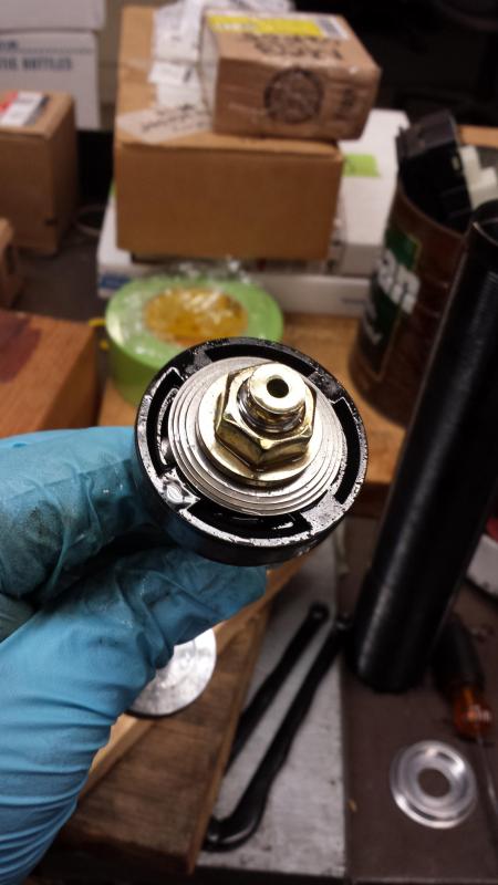
Step 2: Release the pressurized Nitrogen or air from the shock body.
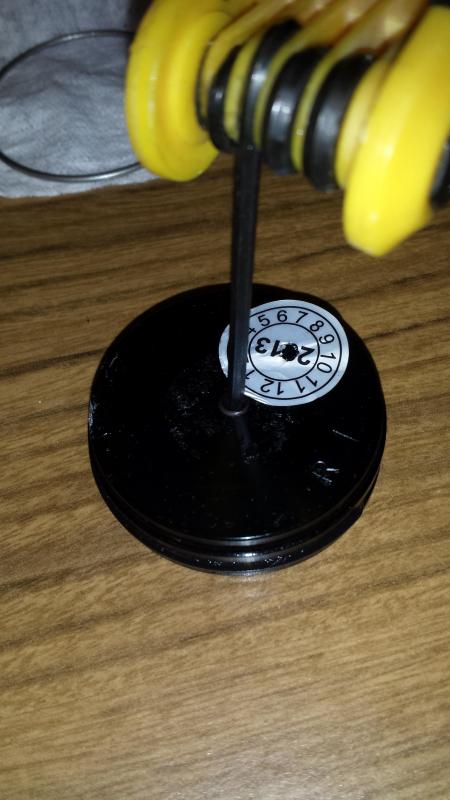
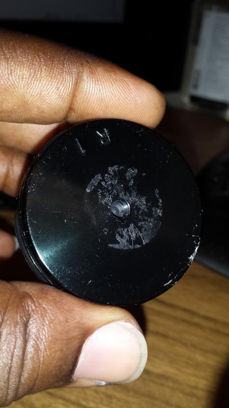
Flip the shock upside down and temporarily remove the circular date sticker.
Use the 3/32" allen wrench, and remove the allen screw from the bottom of the shock body.
(In the picture, I had already removed the shock's base cover. Just imagine it still connected to the bottom of the shock.
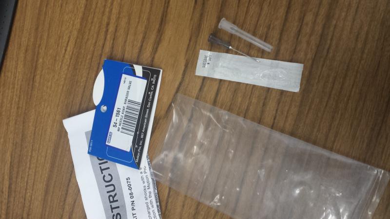
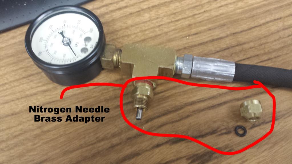
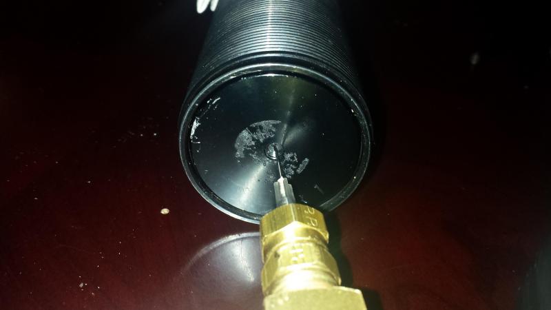
Once the allen screw is removed, you will see a self healing rubber-like seal. You will then take your nitrogen needle and secure it into the nitrogen needle brass fitting with the necessary rubber O-ring and pierce the self healing rubber seal with the nitrogen needle to relieve the pressure from the shock (175 psi of pressure). Make sure to direct the pressure away from your face.
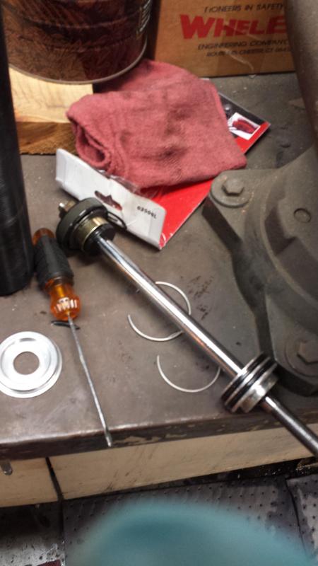
Once all the pressure is released, you can push in by hand on the bottom end cap (or tap/push in with the wooden or rubber handle of a hammer...NOT the metal hammer head, use the handle). Once you do this, you will then see the lower c-clip that needs to be removed.
_______________________
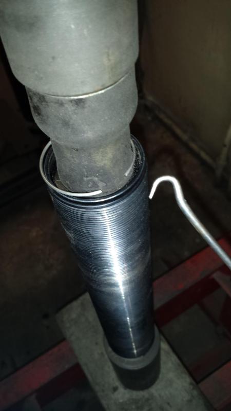
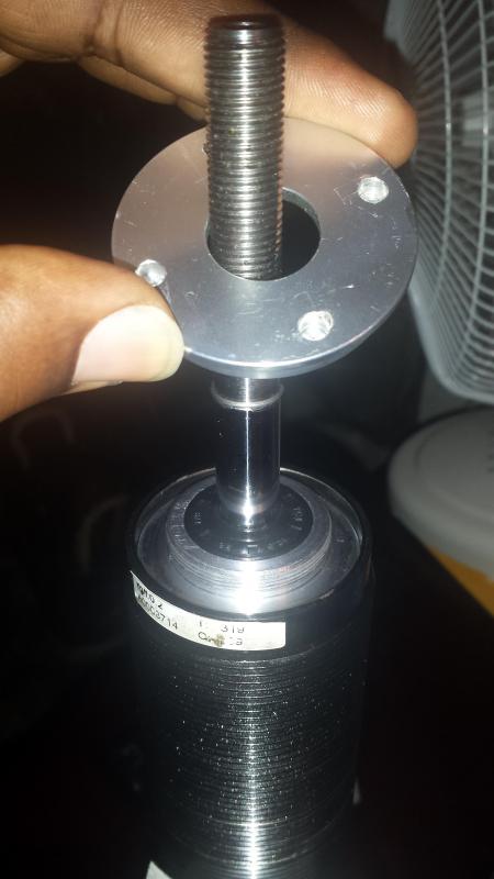
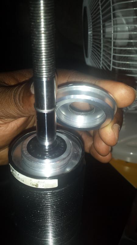
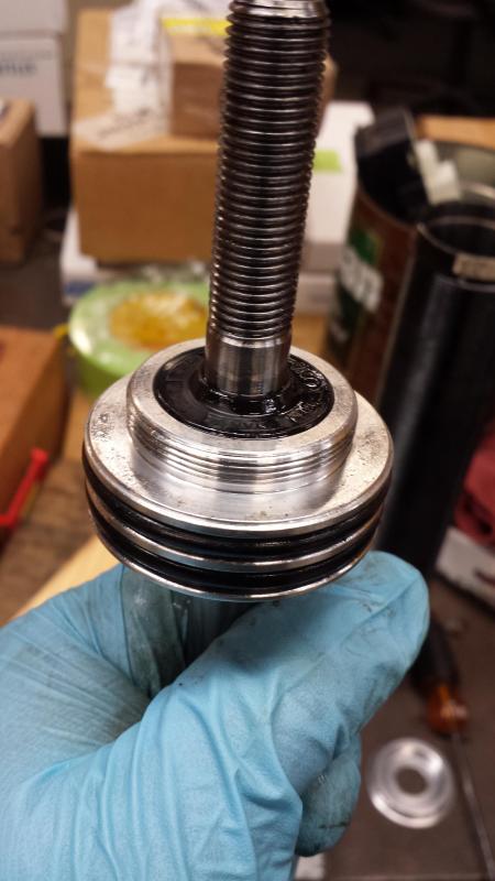
Step 3: Remove top dust cap
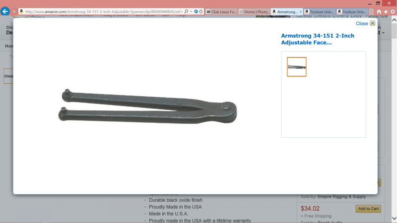
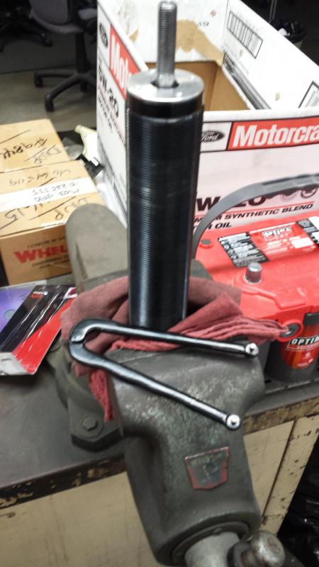
Use the 2" adjustable pin wrench aka spanner wrench and place it on the top aluminum dust cap making sure to align the pins of the wrench with 2 of the 4 holes in the dust cap. Then twist the cap counter clockwise to remove and lift the dust cap from the top seal head of the shock. EDIT: Notice the table vise holding the shock. Instead use a plumbers vise or pipe vise with rags to grip the shock body. I highly recommend this so you don't run the risk of crunching any shock body threads. If you cannot find a plumber in your area that will let you use his vise for a buck or two, then you have to use a regular table vise as a last resort.
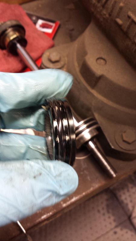
This is the shock "Dust Cap" which is in my hand. The "Seal head" aka "wiper seal" is still in the shock body[silver w/ black rubber center]
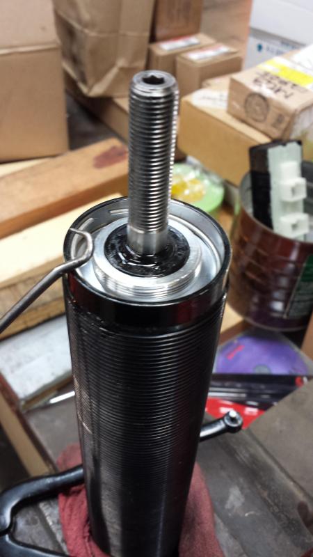
Push down on the top seal head (silver with black rubber in the center) by hand or hammer handle (DO NOT PUSH DOWN BY SHAFT HERE!) and remove the inner c-clip as well from the shock.
If you happen to have pushed down by the shaft and it is stuck in the seal head/ wiper piston, then firmly lift out and remove the stuck shaft, seal head, and damper valve piston from the shock. Place the threaded shaft end in one hand, and the seal head piston in the other and quickly yank them apart. Be sure to watch your finger so they do not get crushed or slammed in between the seal head and the damper valve piston (like I did) while you are pulling these 2 items apart.
In this picture I pushed down on the shaft [you are supposed to push on seal head only], and the small metal c-ring on the shaft [see the picture above this one] got stuck inside the seal head. I had to lift out and remove the stuck shaft and seal head from the shock. Then yank on the shaft and seal head to break it free again.
Now you can slowly, and firmly lift up on the shock shaft to lift the shock innards up and out of the shock body. Try not to spill any oil at all. And for anyone performing this, please measure how much oil is in the shock body. On my first try I pulled too hard and the oil spilled all over the floor. So I do not have an exact measurement of how much oil is contained in the strut. From what I found on a nissan forum, the BC racing RM type contained 125ml of oil, but this was nissan. I am not sure the weight, but if you are rebuilding you can choose what you want based on your design. Just make sure to buy good shock oil that doesn't breakdown under heat. The weight of the oil can also add to or reduce force pressures generated by the shock's shim stack on the shock dyno.
The thicker the oil is, the harder it is to force it through the orifice holes of the piston. Thus requiring more force to get it flow through.
The thinner the oil is, the easier it flows through the piston orifices. Thus requiring less force to move the oil through the piston orifices.(This gives you less forces on both the compression and rebound halves of your shock dyno)
Through all the research I have been doing, I have seen the range oil used as either 5w, 6w, or 10w. 5w being the thinnest of course.
I would strongly recommend Off-roading forums, and their shock rebuilding guides to see which brands/companies of shock oil can stand the test of heavy off-roading in hot desert weather.
**For my personal situation, I do believe this to be an issue. When it is 55-60 degrees Fahrenheit in the morning, my BC dampers are more firm just due to the ambient temperature making the oil cold and increasing its viscosity. After 10-15 minutes of heavy, spirited driving, the dampers warm up, and the firm response (due to temperature) is not there anymore (personally,I prefer the firmness). At this point the input responses from the road feel a "little loosey goosey".
This issue is really hard to describe in words, but imagine if you are given two tasks.
The first task is to do a push-up, and at the height of the push-up you must clap your hands, and then catch yourself before your chest hits the floor.
The second task is to do the same as the first task as fast as you possible can, but this time your hands must touch, not clap. And you cannot make a sound upon landing or throughout the process. with the second task there is quite a bit more preciseness.
Maybe this is a sign that I need to introduce more damping force into the damper? I'm not sure at the moment, but I definitely like driving the car more when it is cold out.
I hope this example conveys my experience clearly.
This is a LINEAR PISTON. not a digressive piston. A linear piston can be fashioned to act somewhat similar to a digressive piston. But a straight digressive piston is in a league of its own in terms of forces being able to taper off in the High speed region of the dyno graph. And can also lead to smoother transitions between low speed, mid speed, and high speed forces on the shock graph.
BC racing piston (piston band excluded) = 1.794 inches (45.56mm - measured from the piston itself, not the piston band that goes around it.)
Full BC racing piston + band = 1.813 inches (46.05mm - measured from the piston band, not the piston)
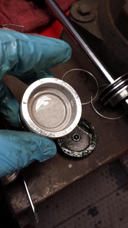
This is the shocks End Cap aka Base Cap/ Plate
This is the Dividing piston, aka Sliding or slider piston
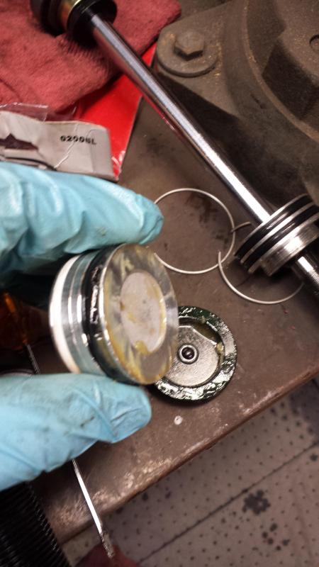
This is the bottom of the Dividing piston, aka Sliding or slider piston
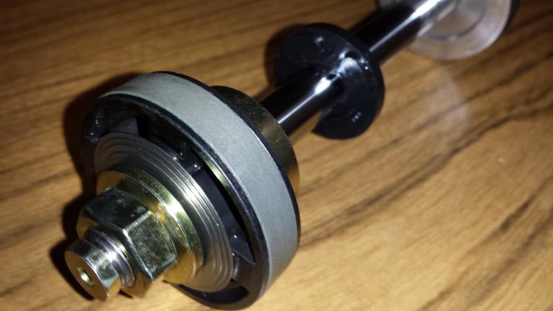
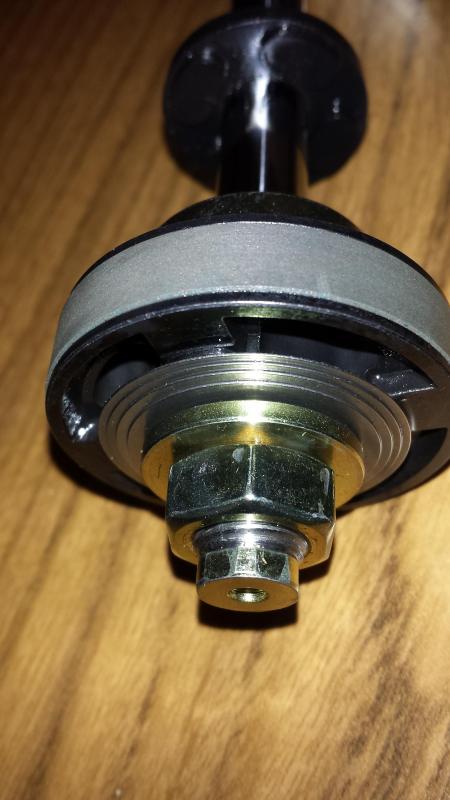
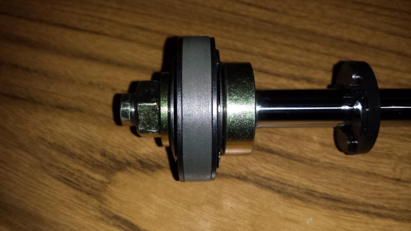
This is the bottom of the "Seal Head" aka "Wiper Seal"
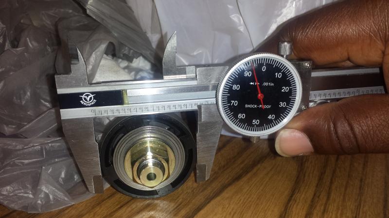
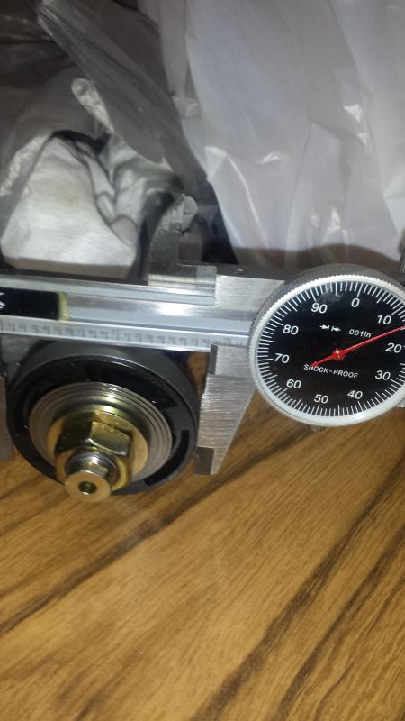
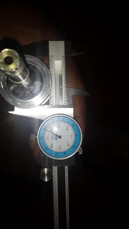
What you see in this picture is the bottom of the seal head that is shown above. I am measuring diameter of the groove/ cutaways for the O-rings. I measured 1.585 inches. So the O-rings inside diameter for the seal head should not [try not to go smaller if possible] be less than 1.585 inches or 40.259mm. Or else the O-ring may be over stretched on the inside.
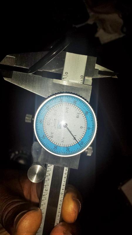
O-Ring thickness. Each individual line in the blue ring of round gauge is 0.01 inches. Add this to the number on the metallic slide bar to get your total thickness. So the O-Ring is 0.127 inches thick (3.226 mm), and the outside diameter should be just shy of 46mm. 46mm will work but it is very tight. So much so that I had to slam the shock body into the carpeted floor a few times just to get the shock's black bottom base plate (the one secured with large C-clip) back into the shock body.
If you ever do a rebuild and need to find a replacement O-ring at a specialty hardware store, just give them this data.
Shock disassembly and recharge video has been made. It is 6 parts. 1st part is currently uploading to youtube. Links will be posted shortly. It's late at night, More to come tomorrow.
No problem guys. I have a lot more info and pics to post. But every time I plan to post them up, something else is in need of attention. I have another 2 - 3 parts for this DIY shock revalve info, and another 3 posts on fix it your self items.
. EDIT: (forgot to add)
Nitrogen Shock Filling adapter tool (PSI gauge w/ high pressure hose and Schrader(tire) valve )
Continued from post above -25 image per post limit reached
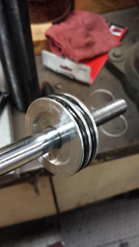
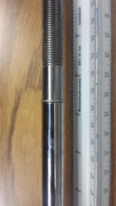
BC racing gs300 1st gen (and I believe all BC lexus models) shock travel is 5-3/8" full extension, with no bump stops.
The whole bc racing shock shaft has a 12.5mm diameter, and is reduced down to a 12mm diameter at the shock piston location/segment.
_________________________________
found old pic.
posted for informational record purposes.
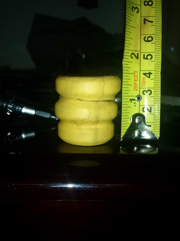
Factory BC Racing Bump stop (stiff as heck) is 1.5 inches in height.
If you have the chance, I would recommend changing these out to a bump stop that is waay more progressive in its compressive strength. The BC bump stops are almost like an "instant on" when you hit them. Which gives a very rough, and abrupt instant stop when you hit them. Versus a gradual resistance force when It comes to compression. I currently have mine cut (as you can see in the picture) to allow for a bit more shock travel and less "bottoming out" as I drive.
Here is a shock Dyno graph of the 8kg/mm shock that I paid a shock shop to have done.
Click the links below to see the shock dyno graph
More pics....
sorry for the delay I have been busy lately. These were taken shortly after the insert was disassembled. (This is an 8kg/mm shock insert/ coil over cartridge)
__________________________
I was once told :
"BC racing coil overs can be revalved by a professional, but they are greatly limited with what you can do, and they are far too much harder to deal with than bilsteins, koni's ext. And because of this they should be avoided. And if you bought them you are screwed for making a foolish decision. You should have bought 'name brand' "
Well I am here to say that I believe the above statement to be wrong, and they can be made/modified even better than their decent stock form. Basically, don't believe all the naysayers, and give up on your BC coil overs. I've been told by many to just take a +$1,000 loss, and throw away the BC's. Buy bilsteins (~$600), lowering springs($250), and new strut mounts($240) and call it quits (~$1,100 total), but the engineering in me finds it hard to do that.
Yes I'm sure bilsteins are great, but I refuse to throw away money if I don't have to. And If I am wrong, well you at least now know how to take apart and refresh/ rebuild your BC racing dampers.
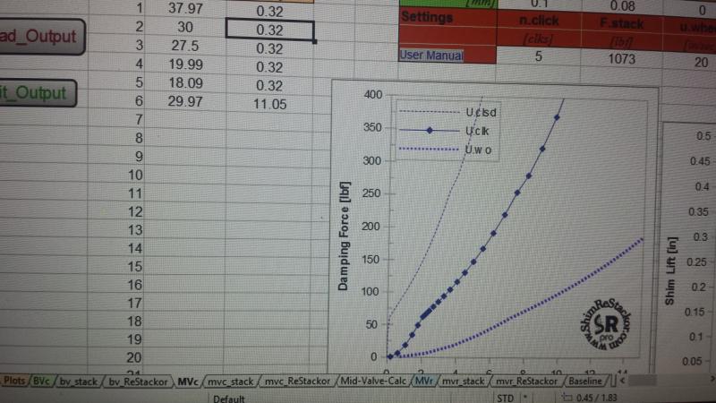
So, I have listed below the numerical measurement data for entry into the $70(Pro version) Excel/ Open Office sheet software called Shim Restackor (google it). The purpose of this software is to give you a very general baseline of what changing various shims will do to your shock dyno plot. It is not a mandatory necessity when it comes to shock revlaving. It is just a tool that can possibly assist a little bit if you are curious to see really rough estimated results without actually disassembling anything. It was initially designed for motor bikes, and motor cycles (I believe), but can also apply to automotive shocks to obtain a general graphical understanding of what shock shim changes do. Please read up on google about the software thoroughly to get an idea. From my testing, the software did not give me exactly the same graph as the physical shock dyno I paid to have performed, but It gave me a great understanding of what changes would happen to my dyno plot at various locations based on my changing a shim here or there on compression or rebound side.
So for example, if I wanted to affect the low speed region of the shock dyno I know what shim or shims to focus on and how much to increase, or decrease in thickness or diameter.
Or if I wanted to shift the low speed to med/high speed transition point, I could find out which shim to make thicker, or where to add an extra 1 or 2 shims to accomplish this.
If you are going to get this software to help you, you might as well get the pro version as it will allow for full access graphs and an unlimited amount of shim entries. But polease read and research thoroughly before you buy. The software needs specific damper piston, and shim measurements to be able to give you info at all. It is fairly cheap, and can greatly help. It is the closest thing to you can get to visual representation without paying +$1,600 for an entry level shock dyno rig.
Also, soon to come later(maybe), I plan to design a DIY shock dyno rig. My goal is to keep it under $400. If it does happen, it will be after this project.
Shim Restackor Snapshot
BC racing Rebound Shim Stack
BC Racing BR Shock Piston - 46mm diameter with piston band installed. Rebound side shown.
Close up of Rebound side of BC racing BR piston - 46mm
Close up of Compression side of the BC racing BR piston - 46mm
.......
The following information can be used in Shim ReStackor to obtain your software generated shock dyno graph.
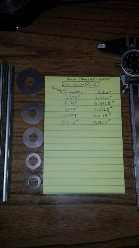
Stock Rebound Shim stack size and arrangement for 8kg/mm shock insert for informational purposes.To be used for reverting back to stock if you are unhappy with your shim design test changes. The term "Diameter" on the yellow note is the Outside Diameter of each shim. The inside Diameter equals 12mm in metric measurements. If you desire, you will have to convert the ODs (outside diameters) and thicknesses to metric on your own.
Compression Shim stack.
This is the Compression side of the shim stack.
DIY Shock Revalve PART 3: BC Racing shock revalve w/ Bilstein internals & shock dynos
********************If any person is going to emulate all of this, please give credit where credit is due********************** PART 3: BC Racing shock revalve w/ Bilstein internals & shock dynos
Link to PART 2:
DIY Shock Revalve PART 2: BC Racing damper cartidge/ insert dissassembly. MANY PICS https://www.clublexus.com/forums/gs-...ml#post8783153
______________________________ DISCLAIMER NOTE: I do not take responsibility for any injury, destruction of property, or results for anyone who will read and perform this whether by following what is described herein or by disassembling in your own fashion. By performing the tasks listed below, you do so at your own risk. The information below is for educational purposes only. I will not be held responsible.
_______________________________
[Shock Dynos at the end.]
Ok in Part 2, I showed how to disassemble the BC racing shock/ damper and its internal parts. In this post I plan to show in general the parts side-by-side, and show the first stage of my BC Racing shock revalve, and the resulting dyno. And how to comprehend the information used to get here. All of my understanding and information regarding this project comes from a few months (on and off) worth of reading and studying all kinds of info on the internet, going through posts on various message boards, and backing it with info from Milliken's book Race Car Vehicle Dynamics. I read a small snippet from a .pdf copy which I got from a friend of a friend of a torrent of a friend...etc. Need less to say, there are ways it can be had (gratis - thebay) for less than the Book price of +$170 on amazon.com.
If you can get your hands on a set of blown or worn BC racing dampers for cheap, go for it.
Some may say why don't you just spend the ~$900- $1000 and just buy bilsteins, custom springs, coilover sleeves & top hats and call it a day. Truth be told, I would have if I did not already spend +1300 for my custom BC racing's BR coilovers with 14K/12K swift spring setup. My first mistake was making an order for such high spring rates without truly understanding Motion ratios, corner weights, natural frequencies, and damping characteristics. And how all of this this affects my ride preference.
If I had to do it again, I probably would have gone straight to bilstein if lowered stance was not a concern. Or I would have at least stayed with the stock 10kg/mm front and the 8kg/mm rear springs to see if that would have given me the comfortable ride but greater handling.
To be honest, I was greatly inspired by the Gixxer-Drew setup for the supra/SC300. My only issue was that it was not ride height adjustable independent of the spring perch. At the time I wanted a bit of the lowered stance look. Also, for those who are interested in the Gixxer-Drew setup, Bilstein does offer the option to shorten the shock bodies to achieve that lower stance look. I am not sure how much they charge. Anyhow...
If there is anywhere that I make a mistake or drop the ball, please feel free to chime in and correct the errors. I am not perfect, and this is my first time ever attempting a revalve of a shock. I am totally fine with making sure the information is correct.
There is no telling who this can inspire or help 5 years from now. I have looked all over the net for the last 5-6 months, and there has not been a single definitive detailed post/tutorial on revalving the BC coilovers. So I am hoping for nothing but success at the end of this whole endeavor. And if this project does not work out, at least it was a great learning experience for me and those reading it.
Oh, and I have not forgot about part 1 of this project (the equations and explanation). It was either that or post my recent results in part 3, and I couldn't wait to post my findings. Part 1 will come a bit later. And I will be editing this routinely, and as I go forward so bear with me.
Now that we have disassembled the shock in part 2, we need to find out which internal parts we would like to use and where to obtain them.
Some things to consider are should you go with a Digressive, Linear, or Progressive piston? What are my intentions for the car? A firmer, yet still compliant ride? Or a stiff setup for drifting/track use? Should I try out Penske's Velocity Dependent Piston(can be Digressive, linear, and progressive in the same graph) or is that overkill for my intentions. Should I change out the stock needle and port with a different size and different needle characteristics? Should I opt for a piston with larger or smaller orifices? Should I get a piston with variable bleed adjustments?
These are just a few questions that I was considering along this path. As of right now, to keep it "plain jane" simple I am only worrying about a digressive piston upgrade and the necessary shim stacks to make my BC racing damper dyno match the Bilstein HD shock dyno for the Toyota supra. Then I will install with 10kg/mm springs in the front and plan to write a review on its performance.
_______________________________
[Sidebar: If this is a success, I may also post how to model the BC shock characteristics after an Ohlins shock setup]
[Another Sidebar: Here is a link to a Miata forum where the user "v67gsr" once owned Ohlins, but bought BC racing coilovers, revalved them like I am doing and said that they felt better than his off the shelf Ohlins. He even has highly sampled dyno graphs which show his 2 different BC racing revalve setups. Basically, the Ohlins felt great[duh...they are Ohlins], but the custom revalve gave him a bit more to be happy about.]
v67gsr said: "I recommend BC.
Be honest with you. I am running BC. I had Ohlins before BC. Biggest reason to switch is because I realized the built quality and potential of BC. It may not mean anything to most of you but my friend has researched and developed the technique to revalve a BC to do what only $3000+ shock can do. It was so good that his suspension won numerous time attack in China. All such performance cost no more than a set of KW V3. For reference. Ohlins is by far the best coilover for NC. My revalved BC is way beyond Ohlins. "
...............
he also responded to a member named "concept":
Concept: So you had $2500 Ohlins and switched over to $1000 BCs? Couldn't your friend re-valve the Ohlins?
When you say "way beyond", it makes things a bit hard to believe.
v67gsr: "Once you get into custom valving setup, “brand” of the shock no longer a big factor. All you care are built quality and tolerance. Yes. My friend can rebuilt Ohlins but he decided not to do so because his customers only care about performance. If the same performance can be achieved with a lot less. Why not.
In my case. I switch to revalve BC, then sold my Ohlins with couple hundreds to pocket. On the other hand, I will have to pay extra thousand if I go with Ohlins revalve route. Is brand name truly worth that much? Not to me, at least.
When I say way beyond, I mean there is no off the shelf system that can perform in such way for that kind of $. You will only see such shcok dyno graph in custom system.
Put all that together. I have a custom system which cost a lot less than any big brand name entry level coilover, but perform on par with any $3000+ custom system. Hard to believe? Yes. But my friend got it done."
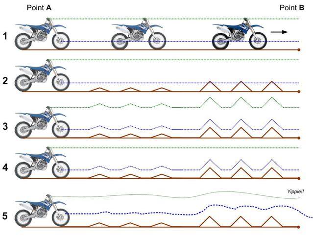
Here is a pictorial representation of the difference between Linear vs Digressive when settings are arranged for priority in body roll/brake dive, and steering response. This picture is courtesy of the thumpertalk forums and davetj123's photobucket. When clicker is set or adjusted for body roll/control, and steering response as priority, Linear can be like #3, and Digressive valving can be like #5, and at best #4. The green dotted line represents the car's interior cabin, and the blue dotted line represents the wheel/suspension.
Here is a graphical representation of a digressive plot (courtesy of z71Tahoesuburban.com)
Here is a graphical representation of a linear plot (courtesy of z71Tahoesuburban.com)
Here is a breakdown of the low speed regions, the "knee", and the high speed regions. Also the Compression and Rebound halves of a graph.
And if any of these links stop working, please "Google" the item to get an idea of what the image is.
A linear piston can be shimmed to act somewhat close to a digressive piston. But a diressive piston is purely as it states. The true benefit of a digressive piston is its "digressive blowoff" in the mid to high-speed region. This is far superior in regards to comfort in the high speed region. The concept of "Blow off" in the digressive valving allows for high speed bumps to just lift the wheel without disrupting the chassis. I personally would only look at a linear piston if I had a track only car. This is because most street tracks have a perfectly smooth driving surface (no pot holes, dips, or blips in the road). So having a digressive blow-off in these situations is not a necessity, although the digressive will still function fine.
STEP 1 - Obtain the desired type of piston
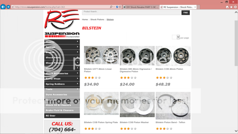
Below is a picture of the Standard "old school" Bilstein Digressive 46mm piston I used. I purchased the 12mm inside bore version, NOT the smaller 8mm inside bore. The bc racing internal piston shaft diameter is 12mm. The piston can be bought from http://store.resuspension.com/home.php?cat=363 for ~$24. What is listed on their site is the 8mm version, so when I called they took my name and told me to buy the 8mm version through the website, and they would send out the 12mm bore version. I also put in the notes at purchase checkout that I was buying the 12mm version. The Bilstein 46mm shock piston is an even double digressive, or 50/50 digressive piston. This means that the no matter which side of the piston is facing up or down, or if it is flipped over, the amount of fluid flow will be the same on either side without any shims added yet.
EDIT: (2/13/15) REsuspension has restocked their inventory of the Bilstein 46mm OD, 12mm ID piston. Before ordering call and ask them if it is the B46-699 old piston design or is it the new COB style. The pricing is now ~$48 per shock piston.
If it is not the old piston design and you still desire the "old school" 46mm piston, you can buy the "old school" 8mm ID (inside diameter) version and take it to a machine shop. There they can bore the center diameter out to 12mm. The 8mm piston is still listed as $24 instead of $48, and I believe it to be the same. I heard from one of the workers at REsuspension that some of their customers have done this.
Also, Fastline Performance also sells the Bilstein pistons.
-EDIT: (2/19/15) I was informed by Fastline Performance Shocks that bilstein no longer makes the "old school" standard piston (part no. B46-699 which is displayed next to the BC racing piston in the 4th picture below). Instead, all of their standard pistons are the COB style of piston without the spring and washer plates. I was told even though they look different on both sides(triangle shaped orifices on one side and square shaped on the other), the flow rates are the same. In whichever direction you choose to face them, just be consistent (if no spring plate & check plate are used) on all 4 shocks. This new digressive piston flows just about the same as the old school digressive piston (I was told).
EDIT: (11/5/2015)
Keep in mind, COB stands for "Compression Only Bypass" . What this means is that Bilstein intended this COB kit (piston, spring plate, and check plate) to be oriented so that the side that the spring plate and check plate "mate" to should be used on the compression side of the shock's stroke. For non-inverted struts that are installed on the vehicle, this direction is facing up toward the sky. NOT facing down toward the pavement.
For me personally, I chose not to use the spring and check plate, as I wanted the same piston effects as the "old school" bilstein piston.
If you use the COB kit as bilstein intended, the COB kit would give the shock some "bleed" on the compression side only and not on the rebound side. Please see the shock dyno picture from the "Hondatech bilstein revalve project picture" shown below. If you look closely, on the blue graph line, on the compression side, there is a dip from 0 - 3 inches/sec. This dip is a result of the "bleed" which is caused by the spring plate and check plate on the compression side of COB piston.
If there was no "bleed" (No check/spring plates, or bleed shims), then the graph would look like the black line.
Dips like this can also be achieved the old fashioned way(COB piston or non-COB) by using bleed shims which are discussed towards the end of this BC racing revalve thread and also in the youtube disassembly video.
The term "bleed" is an allowance of the shock oil to pass through another hole or passage without being forced by/around the "solid" shims (no cutout holes). Your average piston will have little seep or weep hole for this. Other piston manufacturers use bleed shims, as seen in the "DIY BC racing disassembly tutorial video" linked in a previous post here. Some high end piston manufacturers use actual bleed valves that can be manually adjusted or exchanged for different sizes.
On a side note, there is also a Bilstein COB digressive piston. This piston will give a progressive curve in the low speed region, then will turn to a digressive curve after the knee. A good example of this is from this picture which is listed on the Hondatech.com bilstein revalve project. The blue trace line is the Bilstein COB digressive piston using the COB's spring plate and check plate. And the black trace line to blue line would be the standard bilstein digressive piston.
From Hondatech bilstein revalve project post. Bilstein Digressive COB piston(blue) vs Standard Bilstein Digressive piston (black to blue)
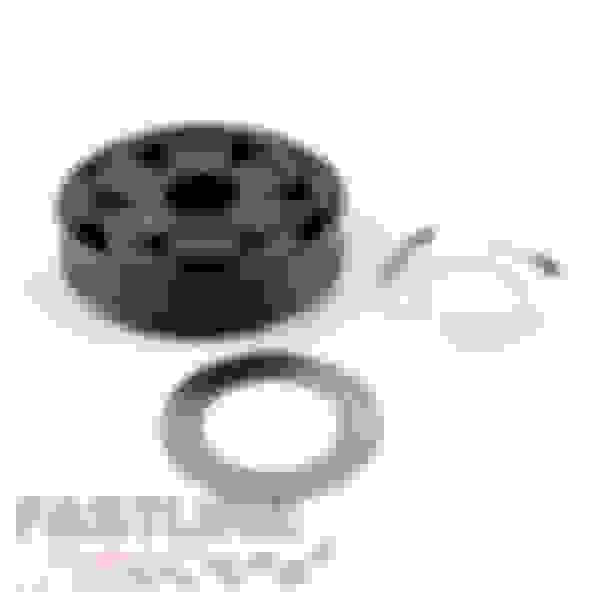
Bilstein 46mm COB Digressive piston kit
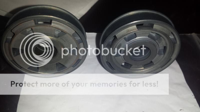
Standard Bilstein Digressive 46mm diameter(B46-699A? - 12mm inside bore) piston on the left [this is what I used for the front shocks]. The Bilsteing piston is a 50/50 or 1:1 ratio piston. The compression and rebound sides have the same size holes, thus allowing for the same quantity of oil fluid to pass. The BC racing 46mm diameter Linear piston on the right and definitely does not have a 1:1 orifice ratio. The compression orifices/side allows much more fluid through, and the rebound orifices/side is far more restrictive.
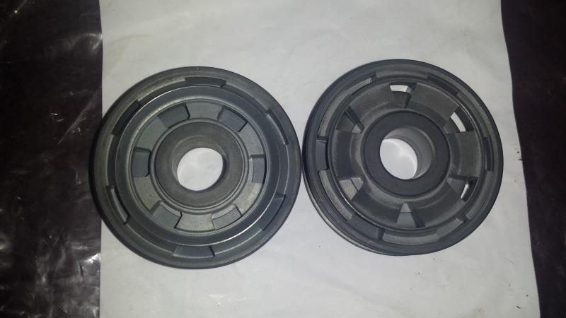
New Bilstein 46mm diameter piston (really a COB piston without the spring and washer plates), that performs the same as the "old school" Bilstein standard piston[see picture above of piston used for my front shocks]. These will be used for my rear shocks. Even though the spring and washer plate side has square shaped orifice holes, the flow rate is still the same as the triangle shaped hole side
Another angle of new Bilstein 46mm diameter piston (really a COB piston without the spring and washer plates), that performs the same as the "old school" Bilstein standard piston[see picture above of piston used for my front shocks].
STEP 2 - Obtain valving manual for the piston and a dyno of desired shock
Now that I had selected which piston I was going with, I went to the Bilstein US website, clicked on downloads(top right of page), scrolled down to motorsports and saved all the .pdf's(8) of the bilstein valving manual. This manual is a total of 78 pages.
I found out about this from this post http://honda-tech.com/road-racing-au...oject-2415915/ Diy bilstein revalve project on Honda-Tech.com .
The next thing to do is to obtain a dyno plot of the desired shock that I want to emulate my BC BR cartridge after.I was able to find a shock dyno of the stock bilstein HD for a MKIV supra from the Gixxer Drew Thread on supraforums [post #792]. The smaller inside curve is the stock supra RZ shock. The larger curve on the outside is the TRD/Bilstein HD shock. The rear shock dyno graph is in the following post.
Supra RZ factory dynos vs TRD/Bilstein HD (US market), these are the fronts.courtesy of Gixxer-Drew & supraforums.
SIDEBAR - Where to Buy O-rings and Seals?:
Below I answered a question from someone online. To locate and find O-rings and Seals, please see the following below. I have heard that first listed contact has every O-ring/Seal you can imagine. I have not needed to used them, but I kept them in my mind if I ever did need an Oring.
QUESTION
Evans Y. - Hey bro where on line can I get the replacement seals at for the rebuild?
RESPONSE
1)
I would start here as I have heard good things about this business for seals and O-rings:
O-Rings & Things
Rating: 4.9/5
19 Google reviews
Hydraulic equipment supplier in San Bernardino County, California
Address: 14546 Hawthorne Ave, Fontana, CA 92335
Phone: (909) 357-7110 https://oringsandthings.com
STEP 3 - Selecting the proper shock shim arrangements.
Now that I at least have a given goal to shoot for, I need to look at my bisltein valving manuals and see what shim arrangement for the digressive piston will yield the needed force. Since I do not own a shock dyno rig, this method should give a baseline to get in a close ballpark of what the TRD bilstein units look like on a shock dyno.
PLEASE DOWNLOAD THE VALVING MANUAL ASAP...BEFORE THE LINKS DISAPPEAR:
Bilstein Motorsports Valving Manual is at the bottom of the page as a pdf link. It is a total of 67 pages. http://www.bilsteinus.com/downloads/...t-information/
Within the Bilstein Motorsport valving manual each page shows a picture of a shock with a shim arrangement, and (2) - 3 digit numbers in the top left corner.
See example:
Example
The first 3 digits [345-top left of page] pertain to rebound stroke, and the last 3 digits [135-top left of page] pertain to the compression stroke. Bilstein has setup their syntax such that the 3 digits signify the amount of kiloNewton force at 20.5 in/sec. So the picture in the example will give a rebound force of 3,450 Newtons @ 20.5 in/sec and a compression force of 1,350 Newtons @ 20.5 in/sec velocity.
1 Newton of force = 0.2248 pounds of force
1 pound of force = 4.4482 Newtons of force
So 3,450 Newtons = 775.59 pounds of force [rebound] @ 20.5 in/sec velocity
And 1,350 Newtons = 303.49 pounds of force [compression] @ 20.5 in/sec velocity
***In simplified real world terms***
For the rebound force picture pointing your finger to the ground and then bending your elbow(while finger stays pointing to ground the whole time) to lift your finger at a speed at 20.5 inches per second. Now tie a rope to your finger, let a 775lb man hang from the end, and lift up at the same speed. This is what your shock will be doing.
For the compression picture pointing you finger to the sky, and moving your finger up into the air at 20.5 inches per second. Now place a 303.49lb man on your finger and perform the same task. This is what your shock will be doing.
*****************************
Now that we understand how to read the bilstein valving manual, we need to look at our desired shock dyno plot.
***Note: If you understand how to obtain slope from the shock dyno graph and use the slope formula equation, feel free to pass this segment.***
***********************************************************************************************
If you have a desired shock dyno graph, chances are it will not go up to 20.5 in/sec. More than likely it will stop off at 15 in/sec velocity. If this is the case, it is ok. You can use simple math to find out what forces your desired shock will have at the 20.5in/sec bilstein valving manual speed. In the shock you are emulating, just find the slope(rise over run[youtube or google "rise over run" or "slope"] on either the compression line or rebound line[whichever you need]) in the high speed region from lets say 10in/sec -15in/sec or even 14in/sec - 15in/sec. Just as long as the area you are taking a sample from is a straight line and not really curved. Once you find the slope (google "finding slope between two points") use the slope formula equation.
Google "slope formula equation"
On the Compression side of the graph, lets assume that at the point of 15in/sec(x1) velocity on the x-axis the shock gives us a resisting force against compression of 300 lbs(y1) on the y-axis. If we want to find out what the force is at the velocity of 20.5in/sec(x2) on the x-axis we can follow the equation below (Provided that the high speed plot is a straight line and not curving) and use the slope(m) we found above to find out how many pounds of force the shock will exert against compression at 20.5 in/sec. For this example slope(m) will be 30 (an increase of 30lbs force for every 1 additional in/sec increase in velocity).
"slope formula":
m = (y1 - y2) / (x1 - x2)
Lets find the Compression pounds of force(y2) @ 20.5 in/sec velocity, then use this to help us find which shim arrangement to follow in the bilstein valving manual.
m (slope of line) = 30
x1=15 in/sec
y1=300lbs
x2=20.5 in/sec
If you put all of the above into the slope formula equation, simplify, and solve for y2 you get:
y2 = -(m * (x1 - x2)) + y1
y2=465lbs of force @ 20.5 in/sec.
*****************************************************************************
On the rebound side of the graph, at 20.5 in/sec the TRD shock has ~783lbs of force.
783 pounds = 3,483 Newtons
3,483 Newtons = 348.3 kiloNewtons (345 in valving manual)
So we should look through the digressive pages in the valving manual and find a page that has the 1st(rebound) 3 digit number of "345" and another page that has the 2nd(compression) 3 digit number listed as "125". Then we should follow the shim arrangements listed in the pictures to achieve the desired goal.
I will post the rest of the info later.
More to come....
With my re-valve I opted for a 345 - 135D shim arrangement. I have posted below a picture of this. After you follow the steps in the PART 2 build, you will need a 17mm wrench and a 5mm socket wrench hex bit to remove the nut on the shock shaft. This will allow you to remove the piston and shock shims.
5mm hex bit use to secure the shaft from rotating as you remove the 17mm nut from the piston side of the shaft. Place the hex bit into the hole the adjustable **** would fit into.
REBOUND REBOUND: This is the shim arrangement I used on my first 1st test revalve. This is for the rebound side. For a shim or two I did not have exact size as specified in the bilstein manual, so I used what I had.
[face of shock piston]
1 - 28mm x 0.1mm
4 - 36mm x 0.25mm
3 - 18mm x 0.30mm
2 - 26.27mm x 2.54mm (back plat is Home Depot washers of 1 inch Outside Diameter x 0.1 inch thickness)
[17mm nut side]
***Note I did not use a Bilstein Bypass plate (part no. B46-743B1 google it ) because I wanted my graph to start from a linear curve and go into a digressive fashion. I used a solid 36mm shim with no cutouts in it. If I had used Bilsteins Bypass plate (aka bypass shim) my dyno would have started with a more progressive shock curve (google it) then to digressive curve. It all depends on what you are trying to achieve. The low speed bleed from the Bypass plate/ shim affects the low speed forces (body roll, lean, initial steering turn in responsiveness, etc). Up to a certain extent, the more of it[low speed forces] can equate to less body roll, and better steering response. The less of it can lead to a more mellow "old Cadillac" slow, relaxed feel. I may install later on just to illustrate the differences in the graph.****
---------------------------------
COMPRESSION COMPRESSION: This was the shim arrangement I used for the compression side of the shock. For 1 or 2 shims I did not have the exact same dimension as the bilstein manual so I worked with what I could put together.
[face of shock piston]
1 - 28mm x 0.30mm
1 - B46-743B1 (Bypass shim/ plate)
4 - 36mm x 0.30mm
1 - 15mm x 1.0mm
1 - 29.95mm x 2.54mm (stock gold colored BC racing stop washer[the small] that is found right beneath 17mm nut)
I did not have some of the shims [thickness] listed in the bilstein manual. But in a situation like this you can double, triple, quad, stack shim sizes to obtain the thickness you need. Just as long as there is room on the shock shaft for the extra shims. For me I kind of did an educated guess on 2 particular shim size thickness', due to the fact that I did not have them in stock. This affected my dyno graph shown at the very end of this thread. So for example, 2 - 36mm x 0.10mm combined are a little more than half (59.2%) as stiff as 1 - 36mm x 0.15mm. The 2 combined shims(0.10+0.10) equaling 0.20 thickness, are a bit softer than the single 0.15 thickness shim. Also, just in case it was not explained earlier, the syntax for shims(metric) goes as so:
What happens when you don't have the right shim [thickness], generally this holds true:
one .15 = 3 -.10 shims (really its 3.375, but rounding to 3 is ok. 3-.10 shims will be 88.8% of .15)
one .20 = 2 -.15 shims or 8 -.10 shims
one .25 = 2 -.20 shims or 5 -.15 shims
one .30 = 2 -.25 shims or 4 -.20 shims
**************
This general equation was found on the thumper talk forums:
(I did not have/find this until after I did my first re-valve test run project. I believe this equation is what I need for my 2nd test run to get the proper shim equivalents(1 or 2 shim sizes were very hard for me to find.) in order for my BC BR shock to have the same shock dyno as the TRD shocks.)
A = shim thickness you need or are trying to find the equivalent using thinner shims.
B = shim thickness you have in stock.
z = quantity of B needed to equal the thickness of "A".
z = (A/B)^3
So if I needed to have a 36mm x 0.60mmshim as specified in the bilstein manual, and I had several 36mm x 0.30mm shims in my stock, here is how many(z) 36mm x 0.30mm shims I would need to equate to one of bilsteins 36mm x 0.60mm .
z = (0.6/0.3)^3
z = 8 - of those 0.30mm shims to equal the one bilstein 0.60mm shim.
In this first test I guessed wrong and used 4 instead of 8... Hence why my dyno graph has less force and looks like it is more suited for a 6kg/mm spring [used in the rear]. Although this first test revalve is intended for the front of the car, the results are actually closer to the rear TRD shock dyno plot. My 2nd revalve should be better
***********
I put the given shims in the pictures above on the shock shaft, and tightened the 17mm nut on the shaft.
Then I turned to my empty shock body. I made sure it was very clean internally and there were no indications of lint or dirt anywhere. The same level of cleanliness should apply to all the other internal shock parts. If not, failure can occur over time due to the abrasive materials scraping around on the inside of the shock.
I re-assembled the shock body by putting the black metal end cap(posses' a mini hex screw where the pressure is relieved from) into the bottom of the shock body, and inserting the large c-clip/ring clip back into the shock base after it.
I then used a broom handle to measure the enclosed length portion of the shock shaft (under full compression, the portion of the shock shaft that lies inside the shock). Then I took the measured broom handle added another 3/4 to 1 inch extra [EDIT: on a full bodied shock, not the short body version], and with the concave side of the slider piston facing upward/out of the shock, I used the broom to push the sliding piston (aka dividing piston) down into the shock body up to the measured length. EDIT(6/30/15): Instead of adding an extra 3/4 to 1 inch of measurement for the sliding piston, I now just temporarily put the tightened and secured piston/shaft back into the shock body w/ the wiper seal piston in its normal location (just below the inside upper c-clip indent line), and use a ruler to measure the length from the piston's tightening nut to the inside lip of the shock body (done with shock shaft in its full compression location). Then divide this distance by 2.
Now push the sliding piston into the shock body this distance. So now you have your sliding piston exactly half way between the base of the shock body, shock and the shock piston's internal tightening nut (under full compression). This way your siding piston will not make contact with the bottom of the shaft nut.
Note: I do not know the exact stock location of the stock sliding piston. But the information I posted worked for me perfectly. I did not experience any contact between the internal parts of the shock.
Now that our slider piston is in its location inside of the shock body, we can pour the shock oil in.
I poured the Maxima Racing High Performance Shock Fluid oil- 10wt Heavy Grade that I had bought on ebay/ amazon.com into the empty BC racing threaded shock body (black outside, stainless steel inside). I was told this shock oil is one of the best out there. Under the Maxima fluid description, it mentions to use their heavy oil for Ohlins, and Fox Shocks. When pouring the oil in the shock body, it is best to pour it in the same fashion as pouring a glass of sparkling cider/ carbonated water. When pouring the cider you'd tip the glass, and pour slowly to avoid losing the carbonation or bubbles.
I poured the shock oil like this to avoid adding air bubbles into the oil by pouring too fast. If you get air bubbles in the oil, make sure you fill the shock body about 1.5 to 2.0 inches below the brim and sit it on a level surface upright and wait. It may take 5 to 10 minutes for all of the air bubbles to fully rise out of the shock oil. Just periodically keep looking down the shock body to see if all of the air bubbles are gone. The recommendation of filling with the shock oil 1.5 to 2.0 inches below the brim will allow for an easy installation of the wiper seal and C-clip when the time comes. After the shock is properly pressurized the air won't be too much of an issue, provided there is not an excessive amount in the shock.
Different oil weights can add to the static force settings of the piston shim arrangement. The thicker the oil is the harder the oil is to move through the piston, which gives a bit more force in the resistance to movement.
And for a thinner oil weight (2.5w, 5w) it will move more freely through the orifices of the piston and shims. The oil in this instance is lower in viscousity and does not add extra shock force due to its lower resistance to movement
****EDIT: after speaking with a reputable shock shop, just use the 10 wt oil, and model your shims around this. The maxima heavy 10 wt shown in the pic below is also used in Ohlins and Fox shocks. the shop uses 10wt for cars, and the 7wt, 5wt, and 2.5 wt for dirtbikes and motorcycles.*****
 11-10-14, 08:59 PM


.tif)