When you click on links to various merchants on this site and make a purchase, this can result in this site earning a commission. Affiliate programs and affiliations include, but are not limited to, the eBay Partner Network.
Now that we have our BC Racing oil filled shock body with limited air bubbles we must insert our shock shaft.
But, before inserting the shock shaft, we must lay down some paper towels/shop towels under and around the shock to absorb the oil that will fall out. And we must put our piston bands in place on the piston.
After discussion with a shock shop, I went with bilstein's teflon bands. What I was told is the bilstein steel bands(coated with some sacrificial material) are used in race applications where rebuilds are done quite often. The theory is that at the granular level there is less friction with a steel band. For me, I thought about long term life and rebuild ability after wear. I chose teflon because steel shock body vs teflon bands sounds better than steel shock body vs steel bands. And also the shop guaranteed that there would be no difference felt whatsoever between upgrading to steel piston bands. The choice is yours. BTW, I have a set (2) of unused steel bilstein piston bands if anyone is interested .
Teflon Band Bilstein Teflon Band for 46mm piston
Steel Band Bilstein Steel Band for 46mm piston EDIT (8/10/15): I just spoke with REsuspensions, and the steel band is actually a copper metal band, with a Teflon coating around the outer part of it. This gentleman also said that the Bilstein metal (copper) piston band actually seals better than the 100% Teflon Bilstein piston band. He also reassured me that my fear of destroying the shock's interior wall by metal on metal contact (if used past maintenance due date) should not be a concern. The copper piston band is a much softer metal than the steel shock body. So the copper band will wear away with use over time instead of scoring or ruining the inside steel shock body
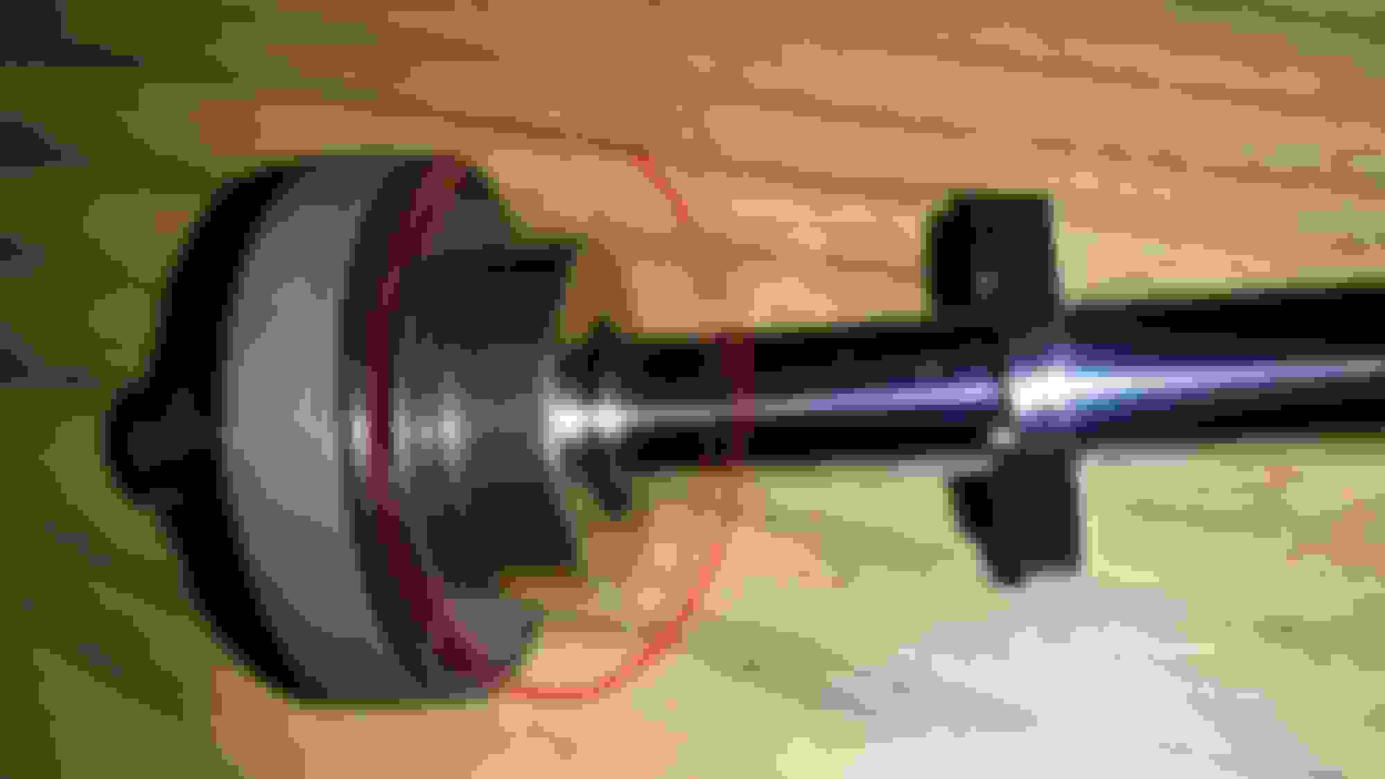
When inserting the shaft, make sure to wrap the teflon piston bands around the bilstein piston, and secure it in place (hold both ends together with thumb) as you line up and slide the shock shaft into the piston. Similar to this picture from a Toyota Sequoia, except imagine this guys middle finder holding both ends of the piston band together in place [piston is silver color with red shims on top of it. Not the silver cylinder with the black rubber O-ring]: Example of how to insert a shock shaft/piston into shock body.
Once you have the shock shaft in the body, push straight down onto the shaft until you get the seal head far enough into the shock body so that you can install the c-ring in the inside ring groove at the top of the shock body. For pictures of the seal head, dust cap, and c-ring please see PART 1 of this revalve project.
Now take the dust cap (silver shock top with 4 holes)and screw it back onto the seal head. You can use the spanner wrench to tighten it, just don't make it insanely tight. Firmly snug will be just fine.
Our last step is to re-pressurize the shock. So now we will need to use the Nitrogen needle and the Nitrogen Fill tool from PART 1, and combine these with an air compressor. ***PLEASE SEE LATER IN POST, INSTEAD OF AIR COMPRESSOR FOR TESTING, AND FINAL PRODUCT, USE A PAINTBALL HPA NITROGEN REFILL TANK.***
Perform the same procedure used to remove the air from the shock, only this time you are using the compressor to put air in.
and keep an eye on the gauge. DO NOT excessively overfill the shock with air. I am not sure if this is possible using a needle(may shoot out), but I wouldn't be the first to try. The goal for a short bodied shock(this is a stock BC racing BR shock, NOT the BR Extreme Low kit) like this is to get the pressure to 150psi at the minimum to about 250psi maximum (personally, If I had the extreme low kit I would just keep it at 150psi). I was told this from another reputable shock rebuilding shop. When I built this at the time, the nearest air compressor could only get up to ~115psi. So keep in mind my shock dyno results below are done at this pressure. Pressurizing the shock prevents what known as hysteresis. Hysteresis is when the current state(aka movement) of the shock is affected by its previous state(aka movement). We DO NOT want hysteresis.
After you have pressurized the shock, then screw the allen/hex screw into the base and you are done. Also, do not over screw the allen screw, I made this mistake and screwed it too far and it went past the threads of the shock's base plate and tilted to the side. It was by the grace of God that I was able to turn it right side up, and back it out to be flush with the base plate. So just turn the allen/hex screw just enough to be flush.
There is a great video I saw on youtube of a clear, see-thru shock under hysteresis, but I can't find it at the moment. Basically during hysteresis the oil aerates and foams greatly affecting the shocks performance. This aeration can occur within a split second of the shocks stroke and re-appear every stroke there after. In the video when Hysteresis happened, the dividing piston would rise up as the shock piston was coming down. It looked as if the two came close to colliding only separated by foaming oil. Pressurizing the shock prevents this.
Also, air will work just fine for testing (make sure it is at the minimum 150psi pressure level), but if you don't mind spending a little more you can buy a Nitrogen tank AND Pressure Regulator (the kind used for paintball or wine preservation) for around $80-$100. They can be refilled at some paintball shops, and some wineries. If using a decent sized nitrogen tank, for the first time I would do it outdoors or in an open air area where if you screwed up and let all the nitrogen in the tank out, asphyxiation/suffocation would not occur and you would be fine. In my opinion, when in the testing stages of your shock building, I would just use compressed air. I would not want to waste the nitrogen every time I have to reopen the shock to make adjustments. Once you find your desired shim arrangement, then remove the air and put nitrogen in. Remember 150psi minimum, and 300psi maximum. I read any higher does not really make a difference against hysteresis.
***New note***
for the finished product, nitrogen would be a better suited option for a shock, than air due to the fact that a nitrogen gas charge will not change pressure as the temperature changes. Whereas a regular air charge will change pressure (thus greatly changing the way the shock reacts) when the temperature changes from cold temps to hot summer temps. If it were me, I would stick with only nitrogen for a finished product.
*******
UPDATE: PLEASE SEE THE NEXT PAGE FOR PICS AND INFO ON AN ALL IN ONE PAINTBALL NITROGEN RESSUPPLY KIT...Post #33...the silver colored nitrogen bottle below can work, but would require purchasing excess parts. I DID NOT GO with the silver colored nitrogen bottle shown below.
Nitrogen tank/bottle Nitrogen tank/bottle. This aluminum style used for wine preservation. BE EXTREMELY CAREFUL WHEN USING. NITROGEN CAN DISPLACE AIR. UNDER A MASSIVE LEAK, ASPHYXIATION/SUFFOCATION CAN OCCUR.
There you have it! You have disassembled, re-valved, and re-assembled, and pressurized your BC racing shock. If you have any questions please feel free to ask. And for those attempting this please post your findings and any new information to this post. Those stopping by from the outer realm of the internet please chime in.
I plan to make a you tube video of this endeavor soon. Please keep your eyes open.
Dyno of this shock shim arrangement in the following post.
IMPORTANT TOOL!!
NITROGEN FILL ADAPTER
I forgot to add this in the list of tools above. It can be had for around $50 on amazon or ebay. Or you could make one yourself. I bought mine from ebay.
Nitrogen Fill adapter tool (PSI gauge w/ high pressure hose and Schrader(tire) valve )
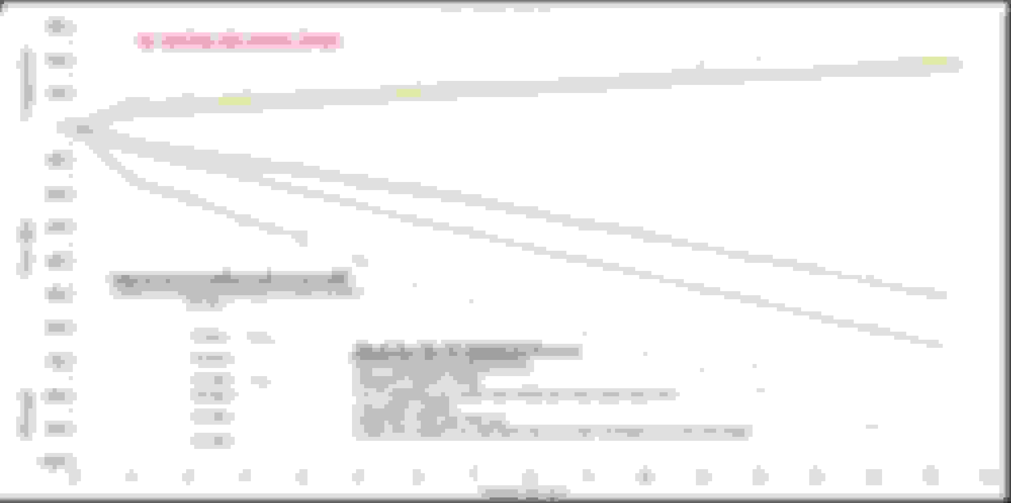
Here is the Dyno of the above shim settings contrasted against the Bilstein HD/TRD supra MK IV shocks(not the smallar supra RZ dyno that is on the inside). I paid $65 for the shock dyno from FEAL suspensions of Ontario, California, and I am happy that I was somewhat, close. This first revalve actually matches the bilstein HD/TRD rear shock dyno. It is virtually spot on. After typing this thread, I believe I know what I need to change to get the identical results of the front TRD/Bilstein shock. I will post these changes as a follow up. ***EDIT: It turns out that this arrangement did not match the Bilstein HD/TRD's for the front of the car, but it indirectly matched the Bilstein HD/TRD setup for the rear of the car. So for the Rear it was a success.***
I hope you all enjoy. SUCCESS FOR THE REAR SHOCKS - ****INDIRECTLY*** SHOCK DYNO: BC Racing Shock with Bilstein Internals. Revalve #1 picture1 - 6 POINT plot sample. Shock dyno was taken from full soft(0 clicks - inside graph) to full hard(30 clicks), at 5 click increments up until 30. the shock was filled with 112psi of air. I need to check if graph will be different at 150 psi[It most likely will have significantly more force in the low speed region (1-2 in/s) on the blue and green lines]. During testing phases, air was used instead of nitrogen because it was a cheaper option. Once shock dyno results are successful, then nitrogen gas charging will be used See shim arrangement below. SHIM ARRANGEMENTS FOR THE GRAPH ABOVE REBOUND SHIM ARRANGEMENT
[face of shock piston]
1 - 28mm x 0.1mm
4 - 36mm x 0.25mm
3 - 18mm x 0.30mm
2 - 26.27mm x 2.54mm (back plat is Home Depot washers of 1 inch Outside Diameter x 0.1 inch thickness)
[17mm nut side]
_________________________ COMPRESSION SHIM ARRANGEMENT
[face of shock piston]
1 - 28mm x 0.30mm
1 - B46-743B1 (Bypass shim/ plate)
4 - 36mm x 0.30mm
1 - 15mm x 1.0mm
1 - 29.95mm x 2.54mm (original, stock gold colored BC racing stop washer[thinner one, not the other thick gold one circled in red below - see pic])
SUPRA REAR SHOCK DYNO: Toyota Supra RZ factory stock vs Toyota Supra TRD package (Bilstein_HD) US market
Please use the front shock graph guidelines in red below to determine the US standard (lbs, in/sec) values of this graph.
.
.
Rear Bilstein HD shock dyno (in chart form) vs BC shock 2nd Revalve. On the lowest setting of the BC 2nd revalve, the difference starts small (~5lbs) but, at the faster shock speeds gets up to ~50lbs on compression and ~70lbs on rebound. I hope the information can be clearly understood.
.
.
.
****Side Note: I was just asked about this. I did not re-install/use this Thick Gold BC Racing stop plate (circled in red) in my revalve. I followed the bilstein guidline. Thick BC Racing stop plate/ shaft port fluid director?
This is a picture of the shock dyno I bought of the stock Rear BC racing shock for our '91-'97 GS300/ Aristo. It comes with an 8kg/mm spring on the coil over. Between the 3 shock dynos, take a glance at the force ranges on each and where the "knee" in each graph is.
Stock BC Racing BR shock 8kg/mm. For 1991-1997Jzs147, aristo, gs300 - 6 POINT plot sample. Shock dyno was taken from full soft(0 clicks) to full hard(30 clicks), at 5 click increments up until 30.
.
.
.
.
******NEW RESULTS************************
2ND REVALVE FOR FRONT SHOCK - SUCCESS 2nd Re-valve attempt - success [just about]. This plot graph was taken starting from full soft "0" at 5 click increments up until "30 clicks".
.
.
SUPRA FRONT SHOCK DYNO: Toyota Supra RZ factory[smaller curver inside] shock vs Toyota Supra TRD package (Bilstein_HD - larger dyno curve on the outside] US market
UPDATE: This shock valving profile is based off of my calculations with a 10kg/mm spring. In true life I used a 14kg/mm spring instead, and the results are great. I would consider the 14kg/mm spring on this 10kg/mm designed shock profile my "70% track/ 30% street" setup. I soon plan to change the springs to a 12kg/mm or 10kg/mm spring just to see the results.
I have just about reached my goal and I am happy with the results of the graph. I have met the 65% of critically damped guideline at the start of my low speed region.The yellow line's compression is a tad bit higher with a few extra lbs of force but it is very close to the Bilstein HD's. And on the Rebound side of the graph the yellow line is also close. And the beauty of it all is if I want to go a bit more firmer than the bilsteins, with just a few kno_b clicks I'm there. The shock was filled to 150psi with nitrogen gas (EDIT: increased it to 200psi, before I installed on the car, personal preferrence-6/12/2015), this way the shock will perform the same in freezing weather and summer weather, and supposedly will be less susceptible to corrosion due to heating and cooling[internal water condensation of air?].
If regular air from a compressor was used, the shock would behave differently under these drastic temperature conditions. And low power air compressors usually cannot get to the 150 psi of minimum pressure needed, that will prevent the oil from aeration, or foaming up under stressful conditions, and disastrously throwing off the shocks performance.
Even the shock shop that dynoed the shock said that it was a great job, and that it was well done. This shock arrangement is for the front of my 1994 GS300 on 10kg/mm springs. The shock was formerly a linearly valved BC racing shock that was valved for an 8kg/mm spring(see stock dyno pic above).
Install/review to come soon.
The shim stacks I used are as follows:
REBOUND (starting from piston face/side going to down to the 17mm shaft tightening nut)
(Quantity) Diameter x Thickness
[SHOCK PISTON SIDE]
(1) 28mm x 0.10mm
(7) 36mm x 0.25mm
(3) 18mm x 0.30mm
(2) - 26.27mm x 2.54mm (back plate is 2- Home Depot washers of 1 inch Outside Diameter x 0.1 inch thickness)
[17mm NUT SIDE]
_________________________________________
COMPRESSION (starting from piston face/side going up towards the adjustable ****)
(Quantity) Diameter x Thickness
[SHOCK PISTON SIDE]
(1) 28mm x 0.30mm
(1) 36mm x 0.20mm
(5) 36mm x 0.30mm
(1) 36mm x 0.25mm
(1) 15mm x 1.00m(1) - 29.95mm x 2.54mm (original, stock gold colored BC racing stop washer [thinner one, [b]NOT the other thick gold one circled in red above..see pic in post above])
[ADJUSTABLE KNO.B SIDE, LOCATED ON THE OTHER END OF SHOCK SHAFT]
Here is the of the home depot washer mentioned a few lines above. Home depot stop washer part numbers. both are the same size and are strong enough to work.
__________________________
I will soon attempt the rear shock valving and post successful results. (EDIT: the first front shock revalve attempt ended up nearly matching the rear bilstein HD/TRD shock dyno)
I have to give a great thanks to FEAL suspensions (Odi and Auto) for helping me with my shock dyno needs. If you are in the So-Cal area, hit them up for shock dyno verification
DIY Shock Revalve PART 1: Shock Damper Equations and how they apply to vehicle ride.
********************If any manufacturer is going to emulate, please give credit where credit is due********************** PART 1: Shock Damper Equations and how they apply to vehicle ride.
In PART 1 I will show how to obtain the essential suspension information needed for a custom revalve of a shock.
The first thing you need to write down is the general information for your vehicle:
-Curb Weight of the car + the Driver’s weight OR the car’s corner weights.
-Front/Rear weight Distribution of the car (or a corner balance data sheet of the car)
-The suspension’s natural frequency you desire (Do you want the car to ride like a soft plush Oldsmobile/Cadillac, a sporty bmw/corvette, or a rigid, jarring F1 indy car on bumpy city streets? Pay attention to the type of roads you will be driving on. If they are not smooth like a race track, you may want to pass on the Indy car option.
Regarding which natural frequency to choose, please view the link below for a visual diagram chart of Frequency vs. Comfort.
natural frequency and ride comfort(subjective) of various cars. The higher the number on the comfort axis, the less comfortable the ride is.
By choosing your desired natural frequency (How fast do you want the spring to respond to road undulations or irregularities), the following equations will give you which spring needed to achieve this.
MR = motion ratio (on the control arm it is the distance relationship between the pivot point and the point of applied resistive force [shock mounting point]) (no unit of measure)
Kw = wheel spring rate (the spring rate seen at the wheel due to motion ratio) – for calculations it needs to be in N/m
Keff = spring rate – for our calculations it needs to be in N/m, so convert kg/mm[or lb/in] to Newton/meter..see below)
pi = the sysmbol PI (which is 3.141592)
ex: How to convert 10kg/mm to N/m
1 kilogram = 9.80665 Newtons
10kg = 98.0665 N
10kg/mm = 98.0665 N/mm
There are 1,000 millimeters(mm) in 1 meter(m).
So to go from N/mm to N/m just multiply by 1,000.
98.0665 N/mm * 1,000 = 98,066.5 N/m
_____________________________________
1991-1997 GS300/ Aristo (jzs147) Specs
Curb weight: 3,660 lbs
Driver weight: 230 lbs
Car Total weight: 3,890 lbs
Weight Distribution: 54%-front / 46%-rear
Corner Weight Percent break down of Curb weight (taken from an SC300, assumed GS300 the same):
Front Left-27.25% (1060 lbs or 480.8kg)
Front Right-26.93% (1048 lbs)
Rear Left-23.72% (923 lbs)
Rear Right-22.09% (859 lbs)
Motion Ratios: Front=0.604, Rear=0.82
How to find the natural frequency with a selected spring rate
Step 1: Calculate your Motion Ratio
A) On the control arm, measure the distance from the pivot point(connects to chassis) to the end of the arm(point where wheel hub mounts to arm)
B) Now on the control arm measure the distance from the pivot point to the mounting point of the shock
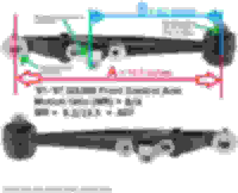
C) Divide the distance in B by the distance in A (B/A). This is your motion ratio (MR). For every "X" amount of inches the wheel moves upward/downward, the shock will compress or extend (MR)*("X") from its initial point. See picture below for Motion ratio of GS300 (jzs147) based on the front control arm. **Keep in mind that the motion ratio has no unit of measure(kg, lbs, Newtons, etc). It is just a plain ratio number.
Motion Ratio From 1st gen GS300 front control arm
Step 2: Enter the spring rate (Keff) you would like to try and find the natural frequency for into the given "Kw" equation to solve for Kw(which is the spring rate seen at the wheel).
For our GS300 lets try a "Keff" of 10kg/mm (or 559 lbs/in in US standards) spring and convert this to Newton/meter.
10kg/mm = 98,066.5 N/m (see above)
A) lets enter the 98,066.5 N/m into our given "Kw" equation of:
Step 3: "Kw" will then be entered along with the car's corner mass ("m" = mass/weight in "kg" seen by the spring on that corner side..[for example: right front corner of vehicle) into your Natural Frequency equation to get your natural frequency. (Note: sqrt = square root)
The GS300's front left mass is 480.8kg (which is 1060lbs). If you have the corner weight in lbs (pounds) we must convert this to "kg" and enter into the equation below.
Natural Frequency (f) = ((1/(2pi)) * (sqrt(Kw/m))
Natural Frequency (f) = ((1/(2pi)) * (sqrt(36,132.5/480.8))
[u]Natural Frequency (f) = 1.38 Hz
So our natural frequency with a 10kg/mm spring is 1.38Hz. Looking at the freq vs. comfort level chart will give you a good idea of where this setup would land. Keep in mind that comfort for the most part is relative from person to person.
If you are seeking a higher or lower natural frequency based on your preference or level of comfort, then you would need to test select a lower or higher spring rate ("Keff") when solving for the Kw equation that will give you the needed the natural frequency.
*****Here is some extra knowledge that discusses vehicle suspension, and how it relates to ride, and what we are trying to calculate. The guy in the video is Shaikh of Fat Cat motorsports. I have watched quite a few of his videos to further understand some areas of "shock theory" that seemed cloudy to me at times. Please have a view and enjoy. This guy is really good at what he does.
Now that we have found out the proper spring rate to give us our desired spring/ride natural frequency, let�s have a look at the actual shocks. Next we will find out how to calculate the critical damping force rate for the spring rate seen at the wheel, and also the damping ratios we may desire to model our shock after.
I will try and keep this simple without getting too technical.
http://upload.wikimedia.org/wikipedi...Ratios.svg.png
As seen in the graph above, the critical damping(damping ratio = 1, also known as 100%) is the line where the symbol zeta = 1. Critical damping occurs when the movement(zeta) in the system(spring and shock) reaches equilibrium as fast as possible in one time period(2pi[zeta=0 time range]) without going through a full cycle or without any overshoot/oscillation(ex. zeta=0.4).
A simpler way is think of your wheel hitting a bump, and your shocks damping ratio is set to the zeta = 0.4 line. As you follow that line from 0 on the left, going toward the right side of the graph, that is the same movement your shock/wheel is doing. your wheel will go up, down, up, then down before it settled. Just like the line zeta =0.4.
The damping forces are attributed to the shock and its shim arrangement inside. Generally speaking, the more shims (of a given thickness) inside the shock(on the compression or rebound side of the internal piston) equates to more force needed to either extend or compress the shock shaft. Selecting good(relative to how you like your ride) damping ratios at each shock shaft speed (1in/s, 2in/s,�15in/sec) will give your shock its overall damping characteristics.
A great read to get even further into shocks and auto suspension/handling�This was one of the sites I read to get a better understanding of what was not making sense to me about suspension systems. After reading through the link, please see the suspension subjects on the left side of the page for more things to learn about. http://farnorthracing.com/autocross_secrets19.html http://farnorthracing.com/autocross_...tml#histograms
Basically with a damping ratio of significantly less than "zeta = 1" on the shock, the spring will be allowed to oscillate(bounce) a few times before it settles down to equilibrium (stops moving).
So any damping ratio under 1(ex. 0.8) technically can be called under damped. But for our use of this methodology, let�s try and stay away from the terms under damped, and slightly under damped because to different users, with different goals, these terms can mean different things. One thing for sure is any system that has a damping ratio of 0% is called un-damped (zeta = 0, or 0%).
A damping ratio of 1(100%) is called critically damped.
Any damping ratio above 1 (ex. 1.25, aka 125%) is called over-damped.
The equations used to find the critical damping (Dcrit_wheel, & Dcrit_coil) are listed below:
(mass must be in kg[kilograms])
Dcrit_wheel = 2 * sqrt(mass * Kw) __________the result of this equation is in Newtons/(meter/sec)
Dcrit_coil = (Dcrit_wheel) / (MR * MR) ___________the result of this equation is in Newtons/(meter/sec)
Dcrit_wheel (this will be used to find Dcrit_coil) is the critical damping force at the wheel based upon the mass and spring rate (NOT the tire�s spring rate� I am talking about the actual spring). Basically it is the amount of force needed at the wheel to make the wheel return to equilibrium as fast as possible in 1 cycle. (See zeta = 1 in the damping graph above).
Dcrit_coil (What we care about)is the critical damping force needed at the shock that will create the critical damping force at the wheel (Dcrit_wheel). The reason for this difference is due to the motion ratio. If the motion ratio was 1.0(the base of the shock is mounted literally at the wheel hub), then for every 1 inch lift of the wheel, the shock shaft would compress 1 inch. In this case Dcrit_wheel and Dcrit_coil would be the same force value.
But on the GS300, the motion ratio(MR) is 0.607. So for every 1 inch the wheel moves up, the shock shaft only compress 0.607 inches (60.7% of wheel lift or drop). This logic works for the wheel lifting(bumps) or dropping(dips) on the road surface. It all comes down to the distance point of where the shock�s base is mounted to on the control arm or wheel hub (see the motion ratio/control arm picture above).
So let�s solve for Dcrit_wheel first using Kw(36,132.5 N/m) and the car's front driver side corner mass(480.8kg) we found from the previous post [sqrt = square root]:
Dcrit_wheel = 2 * sqrt( mass * Kw ) - [in Newtons/(meter/sec)]
Dcrit_wheel = 2* sqrt( 480.8 * 36,132.5 ) Dcrit_wheel = 8,336 N/ (meter/sec)
Now we take our solution for Dcrit_wheel and plug that into the equation for Dcrit_coil:
Dcrit_coil = (Dcrit_wheel) / (MR * MR) - [in Newtons/(meter/sec)]
Dcrit_coil = (8,336) / (0.607 * 0.607) Dcrit_coil = 22,624.5 N/(meter/sec)
We now have our Critical Damping Force(in Newtons [N]) per unit of shaft speed velocity (in m/s). We must now convert this to US standards (lbs, and in/sec). If converting this yourself, you will only need to replace the italicized and Bold "22,624.5N" with your Newton(N) Force result, remove my "128.92 lb/ (in/sec)" answer and solve for your own answer. Only worry about the actual numbers and not the text measurement behind the number (example meter, lb, N...)
I will try and show this conversion as best as possible through text:
So our Critical damping force for the front driver side corner weight(kg) of a GS300 on a 10kg/mm spring in USA standard units is 128.92 lbs of force for every 1 in/sec of shock shaft speed. OR in other words, it takes 128.92lbs of force at 1in/sec velocity to have a critical damping of 1.0 (zeta = 1) or 100% just like in our damping graph above.
So to achieve critical damping(this applies to both compression and rebound) throughout the graph we would follow this equation template:
***Note this is to find the Critical Damping. When building a shock we would want to use a percentage of this critical damping force [i.e. -65% low speed, 25%-35% high speed], and NOT design our shock at exactly 100% damping = critical damping.
Critical damping force = (128.92) * (Velocity[in/sec]).....(I rounded the lbf [lb force] up to 129 lbs)
Now that we have found out our critical damping forces across the shocks velocity graph we are going to design our shocks by taking a percentage of this critically damped force at each shock shaft speed. Then arrange our shock shims (through either trial and error, by experience, or by emulating a known shock shim arrangement/manual [bilstein manual using the bilstein shock piston from the previous post]) to achieve a percentage(i.e. - 65%LS, 25%-35%HS, 10%-15%Very HS) of these forces at the shocks shaft speeds
Then of course you would re-shim the shock�s piston, and dyno the shock to try and meet these percentage force numbers at the given shock speeds.
******NOTE*****
The general rule on the rebound side of the graph is for shock shaft speed forces from 0-3 inches / sec you would multiply the critical damp force at each speed(0,1,2,3) by 0.65 or take ~65% of the critical damping force we just found above at each speed.
And for the shock shaft speeds of 4in/sec and greater you would multiply by 0.35 or take ~35% of the critical damp force we just found above for these higher shock speeds. An extra step (to get a digressive profile) would be to multiply the critical damping force by ~15% - ~10% at speeds approximately greater than 18in/sec to achieve your damping force goals. For a truly digressive profile, the damping force of the shock keeps reducing like a "logarithmic growth"
(google it).
Keep in mind this is general, and will give you a predominantly linear shock curve (without the extra step of 15%-10% for digressive profile, the graph will have the same slope at the higher shaft speeds). For a digressive shock curve, the percentage damping ratio would continue to taper off or decrease(low speed[0-3 inch/sec], to mid speed[4-6 inch/sec], high speed[7-17 inch/sec], very high speed[+18 inch/sec] ) as the shock shaft speeds keep getting higher and higher. These numbers are a kind of generalization. These ranges can shift slightly from person to person based on what their opinion is for each speed range.
High speed Compression forces are usually less than what is used on the high speed rebound side of the shock graph.
On some of the low to mid grade aftermarket coil overs, you will find that they follow another general rule.
For the Compression forces at various velocities (Velo = 1,2,3,..15,16 in/sec..etc):
Low speed force = (2/3) * (Dcrit_coil) *(Velo)
High speed force = (1/3) * (Dcrit_coil) * (Velo)
For Rebound forces at various velocities (Velo[in/sec])::
Low speed force = (3/2) * (Dcrit_coil) *(Velo)
High speed force = (3/4) * (Dcrit_coil) *(Velo)
**************
For fun we will try and match our shocks percent of critical damping characteristics to that of an Ohlins Sportline shock.
The vehicle that the Ohlins shock was on has a front natural frequency of 2.0Hz, and a rear natural frequency of 2.1Hz . The car weighs 3,500lb with the driver included. The spring rate for the front is 7kg/mm[390lb/in], and for the rear it is 5kg/mm[280lb/in].The Motion ratio for the front is 0.97, and for the rear it is 0.99. The car's weight bias is 58%-Front, and 42%-Rear. The un-sprung weight in the front is 121lbs, and for the rear it is 110lbs(This is the weight of the car parts that are below the shock/spring [i.e. -control arm, wheel hub, wheel/tire, caliper, brake pads,…). I believe the car was a Subaru imprezza STi considering that was the message board I got this info from.
This is a % of critical damping vs. velocity(shaft speed) chart. It is an analysis chart of the Ohlins sportline shocks Front and Rear of a Subaru STi(?). This chart is exists courtesy of "4banger" on iwsti.com forums
This is a critical damping analysis chart that I found on the IWSTI.com forums. The direct link is here: http://www.iwsti.com/forums/gd-suspe...trol-more.html
On this post, the original poster listed several data acquisition graphs from all kinds of shock manufacturers (Ohlins sportlines, Tien FLEX, Ground control w/KONI, BC Racing, AST TiC spec, etc..)
Granted the natural frequency is significantly higher than what we calculated(1.38Hz), but we will work with these damping ratio values. If we wanted to match the natural frequency of the STi's 2.0Hz in the front and 2.1Hz in the rear we can use the equations found in part 1. If we apply the critical damping ratio percents listed for the Ohlins sportlines to our 1994 GS300 specs and critical damping on a 10kg/mm spring, we will have a dyno plot that looks like this:
ohlins damping ratios applied to 1st gen gs300 specs and critical damping from a 10kg/mm spring. Done using microsoft excel.
EDIT(6/30/15): In this excel sheet, from 13in/sec and up is a guess based off of the slope of the line in the "OHLINS Sportline 'TiC' Track settings" graph. For those reading this, I might disregard anything above 12 or 13 in/sec. I would repost a corrected screenshot, but I cannot find the excel file, and I don't want to retype it all over again. I will have to admit that even in the graph, there is a significant amount of force in the high speed region. Way more than I would think is necessary, but I do not own a Subaru WRX Sti to try and replicate these settings against or on.
Here are the other shock manufacturers damping ratio profiles. The shock brand is in the title header of each chart. This is all thanks to IWSTI.com and the member "4banger".
enjoy..if you have questions please feel free to ask.
Just some extra info I came across while revalving the passenger side shock. The factory BC racing shock pressure is 175psi.
factory BC racing shock pressure is 175 psi
_________
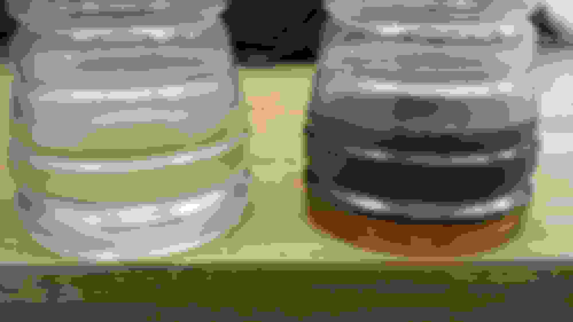
And here is the shock oil difference between the maxima shock(left) oil and the factory BC racing(right) shock oil.
maxima shock fluid(left) oil vs stock bc racing shock fluid(right) oil
maxima shock fluid(left) oil vs stock bc racing shock fluid(right) oil. These are empty 28oz Gatorade bottles used. the BC shock oil on the right is the amount that was taken from the shock body.
This is a post of all the other shock dyno results I had performed during this endeavor and also the shim arrangements for each setup.
This is an example of how the shim arrangements are listed:
(1) 38mm x 0.3mm
means
( 1 - number of shims) [38mm - diameter of each shim] x [0.30mm - thickness of each shim]
Shim arrangement - stock 8kg/mm BC racing shock
Compression
[start from the top face of shock piston first]
(1) 38mm x 0.32mm
(1) 30mm x 0.32mm
(1) 27.5mm x 0.32mm
(1) 20mm x 0.32mm
(1) 18mm x 0.32mm
[end facing shock adjustment clicker]
____________________ Rebound
[start from the bottom face of shock piston first]
(1) 34mm x 0.32mm
(1) 32mm x 0.32mm
(1) 30mm x 0.32mm
(1) 27.5mm x 0.32mm
(1) 20mm x 0.32mm
(1) 18mm x 0.32mm
[end at the 17mm shaft tightening nut]
BC Racing Revalve with bilstein piston. Only charged with 112psi of pressure.
Estimated Results: Same Revalve dyno & internals but with a gas charge pressure of at least 200psi(the pencil markings are an estimate). I drew in pencil, where I estimated the REBOUND shock results to be with the proper gas charge pressure. This was done only for these 4 stiff click settings of 32,30, 25, 20 clicks from soft to hard. This is an educated guess based off of my previous successful dyno results. These results seem to be better suited for a 20kg/mm+ spring....keep in mind, I have not tried/installed any this of my ride. So I am just speculating. I am not sure about the compression considering the pressure is lower than 200psi).
Shim arrangement - "Heavy" BC racing shock Revalve
Compression
[start from the top face of shock piston first]
(1) 28mm x 0.30mm
(1) B46-743B1(Bilstein bleed shim - google it)
(4) 36mm x 0.30mm
(2) 36mm x 0.20mm
(1) 15mm x 1.00mm
[end facing shock adjustment clicker]
____________________
Rebound
[start from the bottom face of shock piston first]
(1) 28mm x 0.10mm
(1) 36mm x 0.30mm
(11) 36mm x 0.25mm
(3) 36mm x 0.20mm
(2) 36mm x 0.15mm
(1) 36mm x 0.10mm
(5) 18mm x 0.30mm
[end at the 17mm shaft tightening nut]
Revalved (by BC racing) IS300 BC racing shocks meant for 16kg/mm springs. The stock IS300 shock comes valved for 10kg/mm springs in the front I believe.
I don't plan to take these apart anytime soon. I may even sell the complete un-opened set to someone who may be interested in trying to revalve.
 01-12-15, 02:32 PM

 .
.


 I wish more people took time to do write-ups like this