DIY: Installing an 01+ radio in a 98-00
 10-08-13, 03:27 PM
#1
Pole Position

Thread Starter

As we all know, the radio plugs for our beloved cars were updated in 2001 for the facelift model. The new radio came with RDS as well as some revised button functions, which means more cool points. Many people have had the misfortune of discovering this plug change after they bought their facelift radio. Maybe I was one of them, but I figured I would make it work instead of selling it. I ended up making a adaptor harness.
Here's what you need:
-a standard Toyota radio harness from any car stereo shop
-the plug from the facelift model (part number 90980-12038)
-several pins for the plug (see note below)
-soldering supplies (soldering iron, solder, heat shrink tubing, etc)
-a precision screwdriver for moving a pin
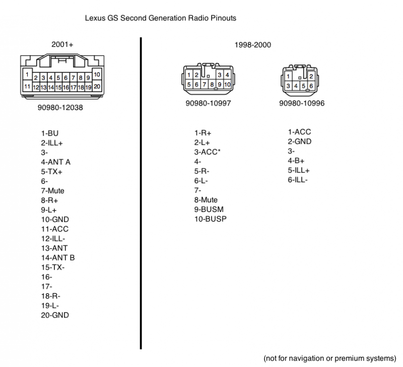
Let's get started. Essentially, all you need to do is connect the pins from the factory harness (via the Toyota harness) to their respective places in the facelift plug by installing new pins in the connector. Now, here's the diagram I made from taking apart both radios and looking at the circuit boards. Please note, the numbers on the pins are the official Toyota layout when looking at the front of the connector.
Now, there are a few things to mention.
-TX+ and TX- are equivalent to BUSP and BUSM
-ANT pins are unused
-The ACC* pin on the original harness feeds ACC power to the amp through the radio on non-facelift cars, hook this up to the other ACC pins when making the harness.
-The pins you need for the facelift plug are 82998-12690 and 82998-12340. They are expensive from the dealer, so I go to junkyards and buy connectors to de-pin.
-It helps to think of the back of the plugs on the radio harness you buy as the front of the ones already in the car.
You need to move one pin on the Toyota radio harness, it should be purple with a black stripe and needs to move to the vacant spot next to it. Take the small screwdriver and find a small retaining inside the plug that holds the pin in, lift it up and pull the pin out, then just slide it into the next spot. Now, insert the loose pins with pigtails into the facelift plug according to the diagram above. Now, using the diagram, solder the wires from the pigtails now in the facelift plug to their equivalents in the radio harness. Some of the connections will be 3 wires, some wires will be left over on the Toyota harness. When you're done, you end up with something like this...
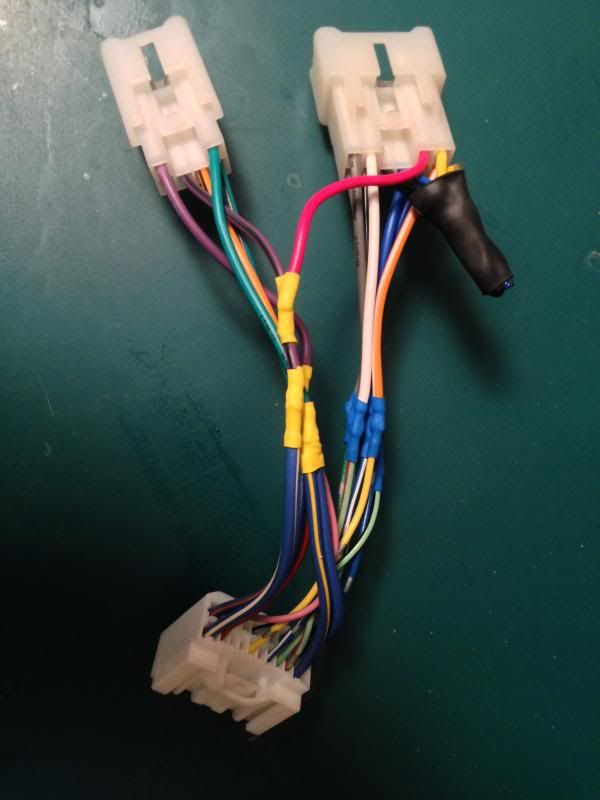
Now, swap out the radios and plug the harness in. If you did everything right, the radio will power up and make sound.
Here's what you need:
-a standard Toyota radio harness from any car stereo shop
-the plug from the facelift model (part number 90980-12038)
-several pins for the plug (see note below)
-soldering supplies (soldering iron, solder, heat shrink tubing, etc)
-a precision screwdriver for moving a pin
Let's get started. Essentially, all you need to do is connect the pins from the factory harness (via the Toyota harness) to their respective places in the facelift plug by installing new pins in the connector. Now, here's the diagram I made from taking apart both radios and looking at the circuit boards. Please note, the numbers on the pins are the official Toyota layout when looking at the front of the connector.

Now, there are a few things to mention.
-TX+ and TX- are equivalent to BUSP and BUSM
-ANT pins are unused
-The ACC* pin on the original harness feeds ACC power to the amp through the radio on non-facelift cars, hook this up to the other ACC pins when making the harness.
-The pins you need for the facelift plug are 82998-12690 and 82998-12340. They are expensive from the dealer, so I go to junkyards and buy connectors to de-pin.
-It helps to think of the back of the plugs on the radio harness you buy as the front of the ones already in the car.
You need to move one pin on the Toyota radio harness, it should be purple with a black stripe and needs to move to the vacant spot next to it. Take the small screwdriver and find a small retaining inside the plug that holds the pin in, lift it up and pull the pin out, then just slide it into the next spot. Now, insert the loose pins with pigtails into the facelift plug according to the diagram above. Now, using the diagram, solder the wires from the pigtails now in the facelift plug to their equivalents in the radio harness. Some of the connections will be 3 wires, some wires will be left over on the Toyota harness. When you're done, you end up with something like this...

Now, swap out the radios and plug the harness in. If you did everything right, the radio will power up and make sound.

 03-29-16, 04:02 PM
#2
7th Gear
Join Date: Dec 2011
Location: Florida
Posts: 7
Likes: 0
Received 0 Likes
on
0 Posts
As we all know, the radio plugs for our beloved cars were updated in 2001 for the facelift model. The new radio came with RDS as well as some revised button functions, which means more cool points. Many people have had the misfortune of discovering this plug change after they bought their facelift radio. Maybe I was one of them, but I figured I would make it work instead of selling it. I ended up making a adaptor harness.
Here's what you need:
-a standard Toyota radio harness from any car stereo shop
-the plug from the facelift model (part number 90980-12038)
-several pins for the plug (see note below)
-soldering supplies (soldering iron, solder, heat shrink tubing, etc)
-a precision screwdriver for moving a pin
Let's get started. Essentially, all you need to do is connect the pins from the factory harness (via the Toyota harness) to their respective places in the facelift plug by installing new pins in the connector. Now, here's the diagram I made from taking apart both radios and looking at the circuit boards. Please note, the numbers on the pins are the official Toyota layout when looking at the front of the connector.
Now, there are a few things to mention.
-TX+ and TX- are equivalent to BUSP and BUSM
-ANT pins are unused
-The ACC* pin on the original harness feeds ACC power to the amp through the radio on non-facelift cars, hook this up to the other ACC pins when making the harness.
-The pins you need for the facelift plug are 82998-12690 and 82998-12340. They are expensive from the dealer, so I go to junkyards and buy connectors to de-pin.
-It helps to think of the back of the plugs on the radio harness you buy as the front of the ones already in the car.
You need to move one pin on the Toyota radio harness, it should be purple with a black stripe and needs to move to the vacant spot next to it. Take the small screwdriver and find a small retaining inside the plug that holds the pin in, lift it up and pull the pin out, then just slide it into the next spot. Now, insert the loose pins with pigtails into the facelift plug according to the diagram above. Now, using the diagram, solder the wires from the pigtails now in the facelift plug to their equivalents in the radio harness. Some of the connections will be 3 wires, some wires will be left over on the Toyota harness. When you're done, you end up with something like this...
Now, swap out the radios and plug the harness in. If you did everything right, the radio will power up and make sound.


 01-23-19, 06:13 AM
#5
01-23-19, 11:16 PM
#6
Trending Topics
01-25-19, 06:50 AM
#8
The photo below shows the back of 01+ radio which also has a second connector with 2 wires. What is this other connector for and why is it not needed within this harness?
 02-17-19, 12:00 PM
#9
Driver School Candidate

Join Date: Feb 2019
Location: Ca
Posts: 1
Likes: 0
Received 0 Likes
on
0 Posts
I have the same questions. The connections in picture of the wiring harness doesn�t make sense to me. I tried but didn�t work. Has anyone gotten it to work? Please help. Thanks.
02-17-19, 05:51 PM
#10
I've created my harness and will be installing this weekend. Will follow up with details after I get it to work. Make sure you are using the correct orientation of the connectors. The image above with the pinouts is looking at the car side connectors. The adapter harness you are building will be the reverse for the 6 and 10-pin connectors. So like the post above you will be looking at the back of your adapter connectors to mate with front of car side connectors. The B+ and BU will be tied together. Pin 10 on the 20-pin is not used.
Last edited by rossmer; 02-18-19 at 05:24 AM.

 02-19-19, 12:23 PM
#12
Has anyone tried to put an SC430 radio with the in-dash 6-disc CD changer in a GS? The 20-pin connector is pinned identical to GS 01+ and in theory this adapter plug would turn on the SC430 radio. The SC control and audio wires to the amp are same as non-ML standard Pioneer in GS. Would be cool to re-gain CD functions with a Grom unit attached. Not sure if radio size and mounting would be similar.
02-20-19, 03:19 PM
#14
I've heard conflicting reports with most saying you lose it including directly from Grom support. Guess I will find out this weekend. I do know there are 2 different Grom cables that can be used on the GS, the TOY1 and the LEX cable. Do you know which one you used?