When you click on links to various merchants on this site and make a purchase, this can result in this site earning a commission. Affiliate programs and affiliations include, but are not limited to, the eBay Partner Network.
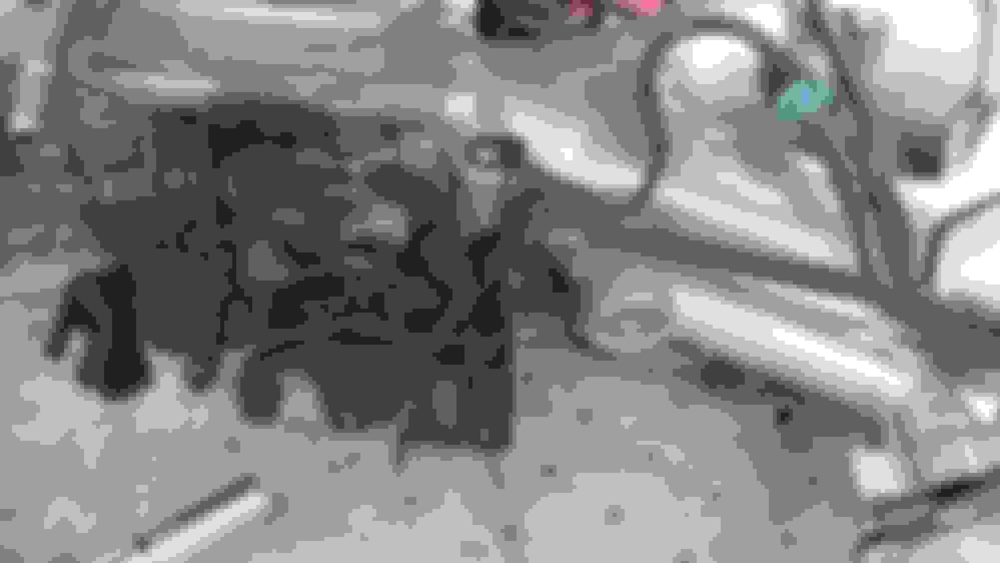
looks great keep up the good work. never seen someone remove the top half of the stock exhaust like that normally those bolts are super locked up but very neat can't wait to see the rest.
looks great keep up the good work. never seen someone remove the top half of the stock exhaust like that normally those bolts are super locked up but very neat can't wait to see the rest.
Ali the air gun really had a time getting those off like that lol.. Guess I got lucky I'm only the 3rd owner and it is an original Colorado car.
The main reason for that method was because I was only going to do the TT-Head Gasket but then decided if I'm already this far better just throw the turbo on lol..
And speaking of this far how does everyone feel about boosting my car with 190,710 miles.. Should I take the extra step and 're-ring the pistons and slap some new bearings in it, or should I put 18 PSI to this guy and see how it pans out with that many miles
And finally, I have a TON of photos to upload to the thread just haven't had time just yet. See you guys soon and hopefully seeing positive BOOST!
if she is a strong runner I would just change the headgasket and arp headstuds and put boost to it.
often times the original rings and pistons on these are in very good shape and rebuilding it can cause more issues unless you have a really trustworthy go to re-builder I wouldn't bother. there have been people boosting these motors with over 300k. as long as it was maintained it shouldn't be a problem.
you can do a compression test, but if you have been driving it and its running strong, not overheating, making good power, idling smooth, no sludge in the top end, headgasket was not severley blown (you will know when you take it off), then I would not hesitate whatsoever to slap a turbo to it, thats the best part about these cars the blocks do not take much wear from regular use, as long as it was regularly maintained.
If you had excessive oil blowby problems in n/a form then that would be a sign the motor is having ring issues or a BHG, but I haven't seen many 2jzge's on its last leg like that.
If you take off the oil cap and can feel exhaust pulsing out then the rings are likely shot, but most of the time this is not the case as the GE bottom end is pretty beefy.
do check on your timing belt while you are in there, if you haven't done the timing belt and waterpump, now would be the perfect time. if you run into any major snags you can reach me on private messaging and I can help you out. hopefully its running for the toyota meet but don't rush it take your time and make sure its all right.
Wow!! I never imagined my car being a feature car on the home page. I will definitely keep the goods coming guys and thanks so much for all the support and outstanding information from other members. There is a lot of good info on here just got to search.
Alright guys, its been a week and a lot got accomplished. I have a ton of pics for everyone, so I may be breaking this into a few posts.. lets start with these
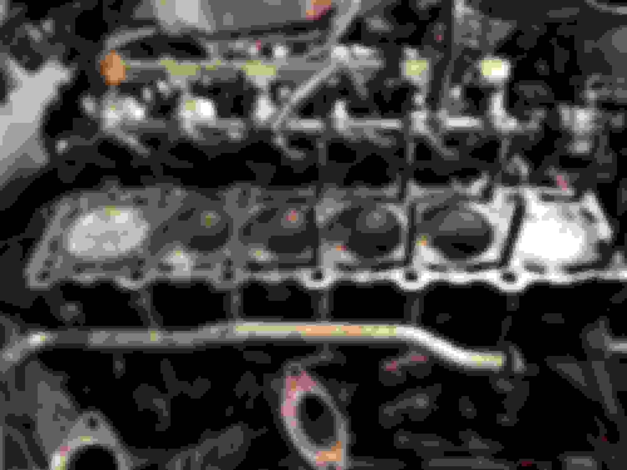
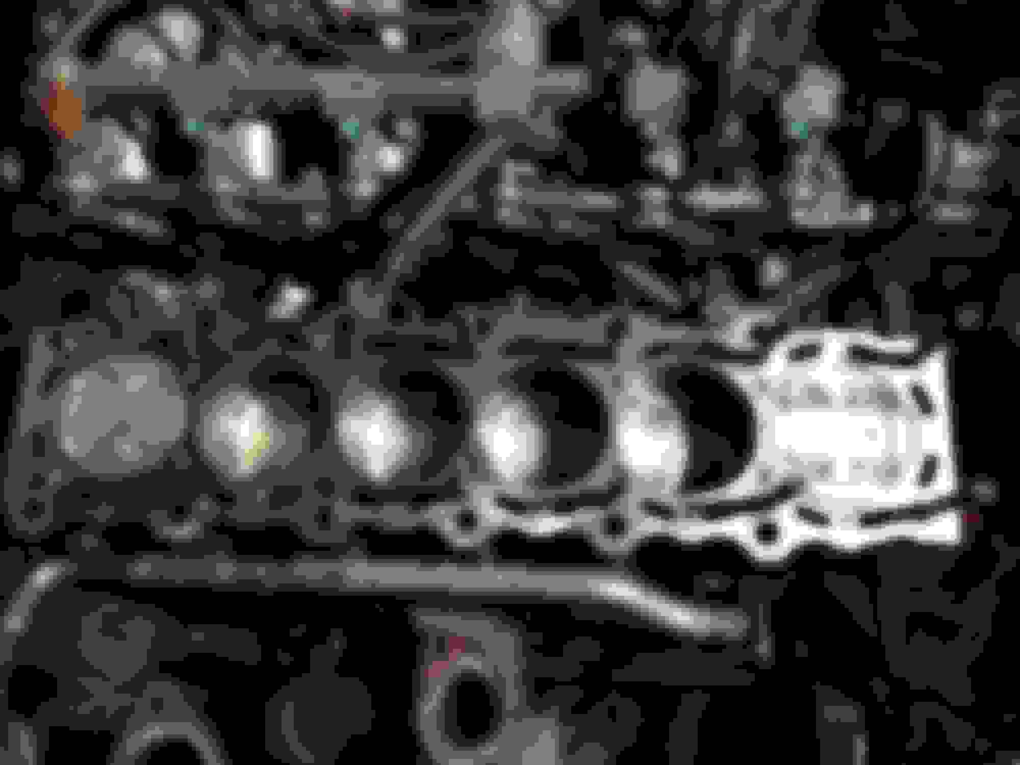
Got the Cylinder Head off and to my surprise this thing didn't look half bad IMO.. especially for having near 200k on him
Fairly clean on the Intake side and a little carbon build up on the exhaust. Hell you can even see Cross-Hatching on the cylinder walls still.. this blew my mind.
Oh and, here is proof for all of you BG product users.. I run MOA in every oil change and 44K in every 3rd tank. Some say this is over kill.. I say here is proof
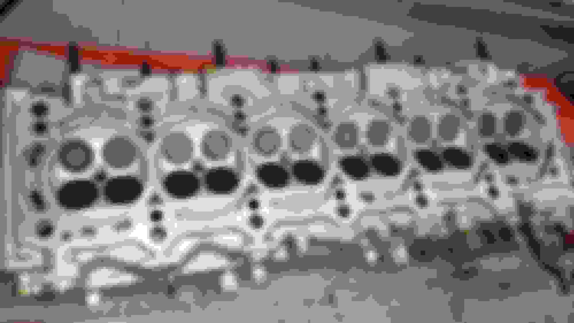
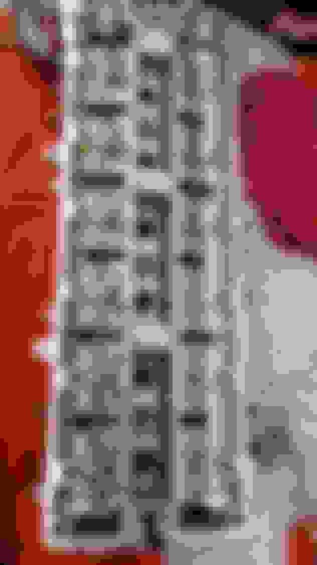
underside of the cylinder head before cleaning and spring and seals are removed
top side of the cylinder head with the lifter caps removed and before cleaning. I have seen a lot of heads sledged up on this side .. glad mine has been maintained well
Here are the Lifter caps removed and labeled you can barely see the "R" peeking out on the right side of the picture..
D/P/R = Driver Side/Pass. Side/ Rear
Obviously F/P = Front/Pass. Side
Also note to anyone rebuilding their Cylinder Head ALL OF THE COMPONENTS THAT ARE NOT REPLACED NEED TO BE PUT BACK IN THEIR ORIGINAL PLACE !! This includes, Valves, Springs, Retainers, Seats, and Most Importantly Keepers
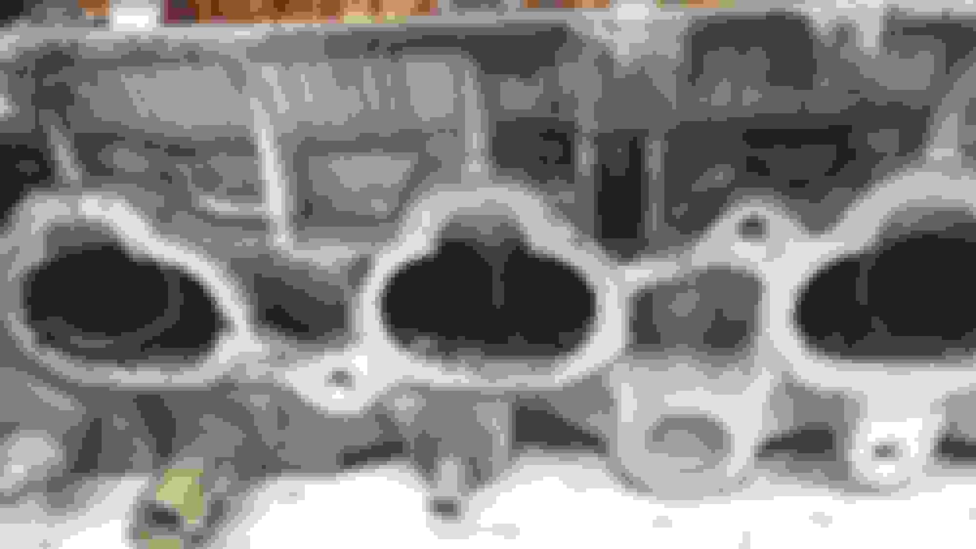
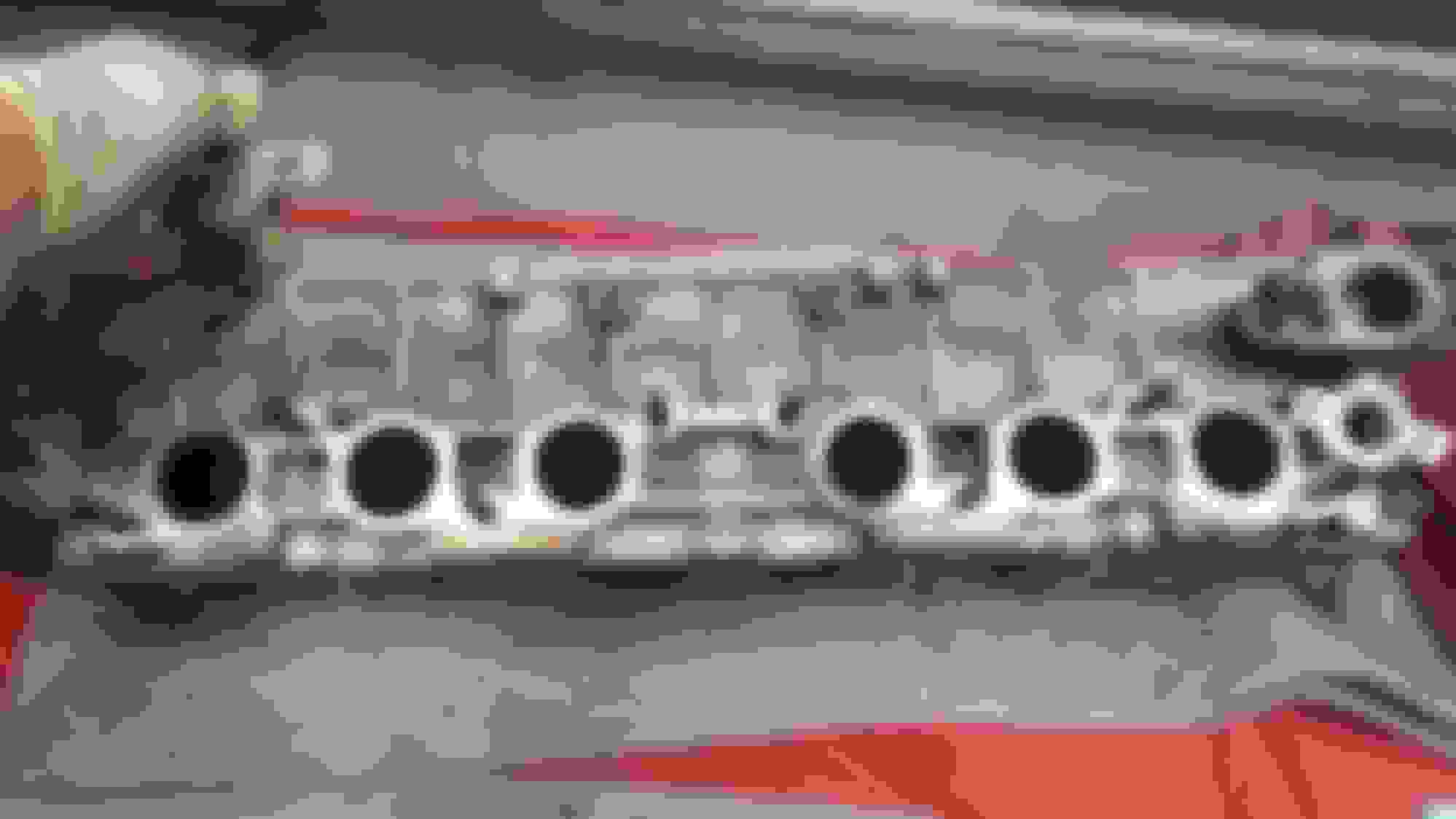
Intake side of the Cylinder head wasn't too bad
A little Carbon, but pretty clean
Quick Exhaust side picture before cleaning
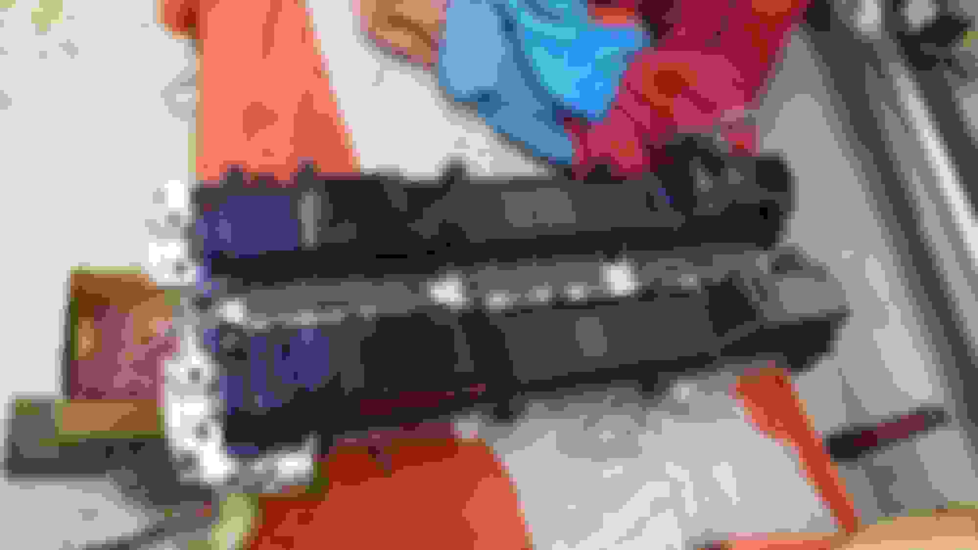
Here is a shot of one of the valve covers before cleaning. I am hoping I can get this guy all pretty again cause I was really hoping to paint them
So Round Two.. I.E. mid week here is what went down
Well well, look how good of a job that was, I can't hardly believe this cover came this clean. I am thoroughly impressed.. I thin I will Paint them now!!
Top side of the valve cover cleaned and ready
Dried off, oil removed, tapped off and ready for paint. Can anyone guess the color?
Picked up some self etching primer to start with. This stuff is acid based primer so it preps metal surfaced for paint to stick to.
Pretty awesome stuff, works really well. If any of you plan to paint metal parts this stuff is the way to start
Getting a nice little base coat going before blasting with color
On to the next thing, they call it Spring cleaning.. I think I did a really good job here..
Got all the Gasket Material and carbon cleaned up.. time to put the final touch on it.
cleaned and very very very lightly hit with a scotch pad to remove as much leftover gasket and carbon as possible.. I did straight edge and feeler gauge this once I was finished
Setting up the special tool to remove the springs and replace the valve stem seals..
For all you DIY'ers, keep in mind that the valve stem seals are different form intake side to exhaust side, you must install them in the correct side.
The exhaust side seals have a bronze Springs on them and are slightly harder to install.
The Intake side seals have a silver spring on them and are easier to install
You can see here that I am doing these one at a time to be sure all components are properly assembled.. Some old original springs and retainers on the left and some new Crower Springs and Titanium Retainers on the right
Here you can kind of see the Bronze Spring at the top of the seal that I was talking about. This is an exhaust side valve and valve seal with the spring and retainer removed.
I did not replace the valve seats that the springs ride on pictured here. I didn't think I would need to, and I did not want to re-shim the lifters as this can get very expensive.
I made it to the half way point!!! Had to move the tool to access the last few.
*Note that if any of you want to do this your self, the camshaft caps have a raised alignment dowel that you can crush when installing this tool if you are not careful. you can see them in the pictures, they look like little black o-rings almost
Cool little pic I took of the new springs and retainers installed
FINALLY ! ! ! ! ! ! ... After two days of slowly cleaning every valve, valve guide, valve seat, and runner port this sucker is completed.
Here is another cool little picture taken for fun, you can see the little cam cap alignment dowels I was talking about really good.. I love the way these look when completed and ready for install
One final little wipe down before loading it up and putting it on.. Not pictured but I did install the Lifter caps from earlier **IN THE EXACT PLACE THEY WERE TAKEN FROM** .... AND........
BAM!!! I figured I would be nice and show you all a sneak peak at the valve covers since I know you have been guessing colors and wanting to know.. So here it is.. I went with color shifting Purple/Blue/Red
Another angle. I also chased the holes for covers with a tap to help avoid any chipping or locking when installing the bolts
And one more for good measure.. hopefully the camera picked up how cool these really came out. They will look amazing installed in the car
Well guys here we are.. I am starting to do the TT-ECU Mod on my car
*** PLEASE READ EVERY PICTURE'S DESCRIPTION**
I decided to go this route with my SC300 because of a few reasons,
I am not fanatical about having all my OBDII functions working, I AM EMISSIONS EXEMPT !, the cost for all that I have was a cheaper reliable route.
Preparing to remove the old Ignitor and Install the DS62 Ignitor for the TT-ECU Mod
***IMPORTANT*** These are the wire colors for a 1997 OBDII SC300
PLEASE SEE MY CORRECTED DIAGRAM FOR A 97+ CAR
C- is WHITE with a BLUE trace (this is C1 on the DS62 Ingnitor)
+B is BLACK with a WHITE trace
Tac is LIGHT GREEN
IGT is WHITE with a GREEN trace
IGF is YELLOW with a RED trace
There is also a BLACK Ground wire that needs to be ran from the new Ignitor to a good ground shown in the next few pictures
Here is a picture of Ignitor pins removed and ready for install on the DS62
ALL PINS INSTALLED INTO THE DS62 IGNITOR.. You can see here the Black ground wire here. This wire is going to be connected to a chassis ground
PLEASE REVIEW ! ! ! ! ! ! ! ! ! ! !
I took Ali SC3's original Diagram, reworked it for us OBDII guys that want to run a stock Dizzy, because the wire colors were different.
In collaboration with Ali SC3 we came up with this !!
Keep in mind when you are OBDII using the Aristo OBDI ECU..
YOU WILL NOT HAVE OBDII FUNCTIONS !!
ONLY DO THIS MOD IF YOU ARE EMISSIONS EXEMPT LIKE I AM OR YOU WILL NOT PASS!!!
YOU WILL LOOSE ALL OBDII RELATED STUFF
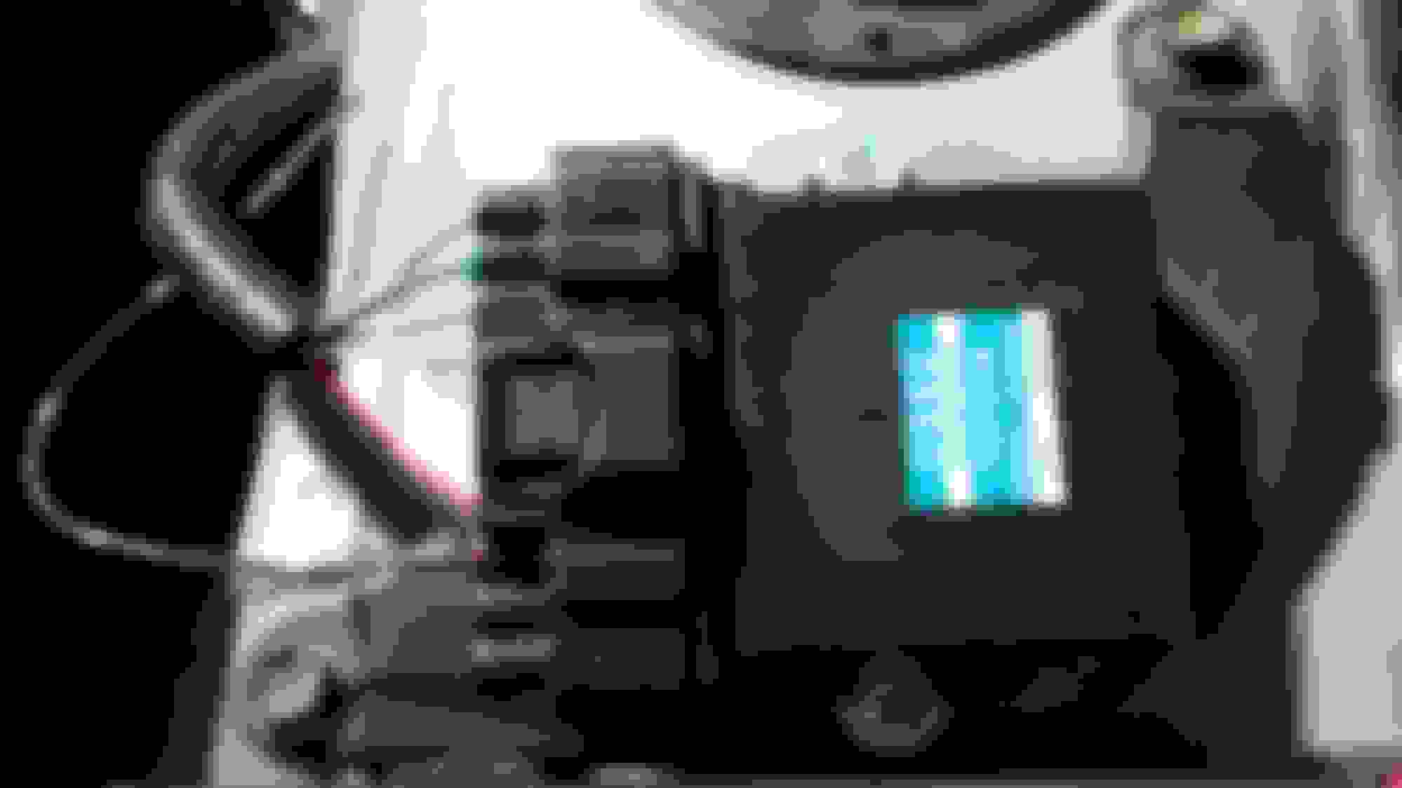
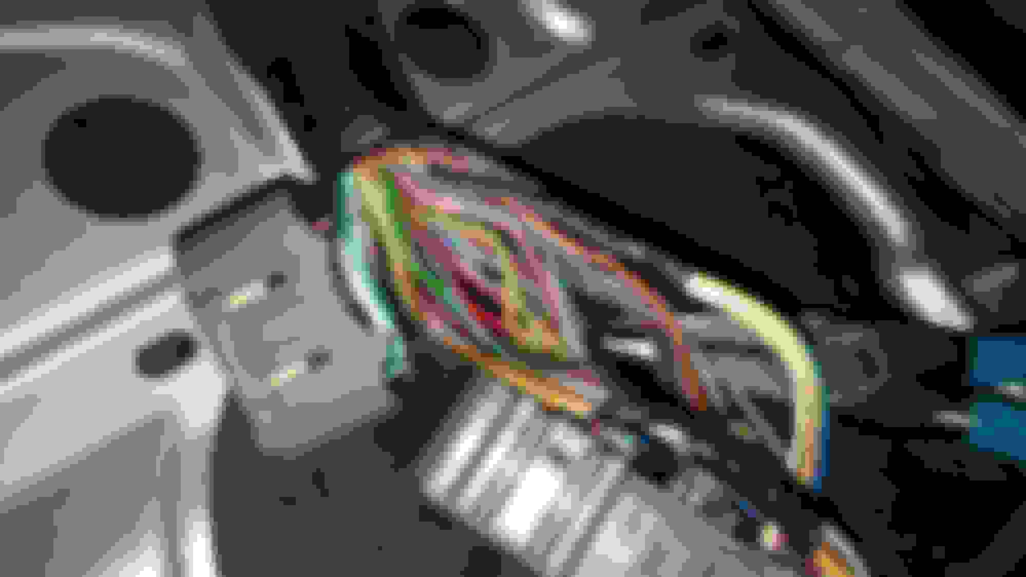
Here is a picture of the connector and Ignitor connected. You can see clearly the wire colors in correspondence with location per Ignitor
[I]Here is another pic slightly more clear showing the labeling on the DS62 Ignitor..
The empty spots are because I am running the stock Dizzy (Distributor). When doing the Coil-on-Plug conversion like Ali SC3 has you will use the extra ports I have Capped.
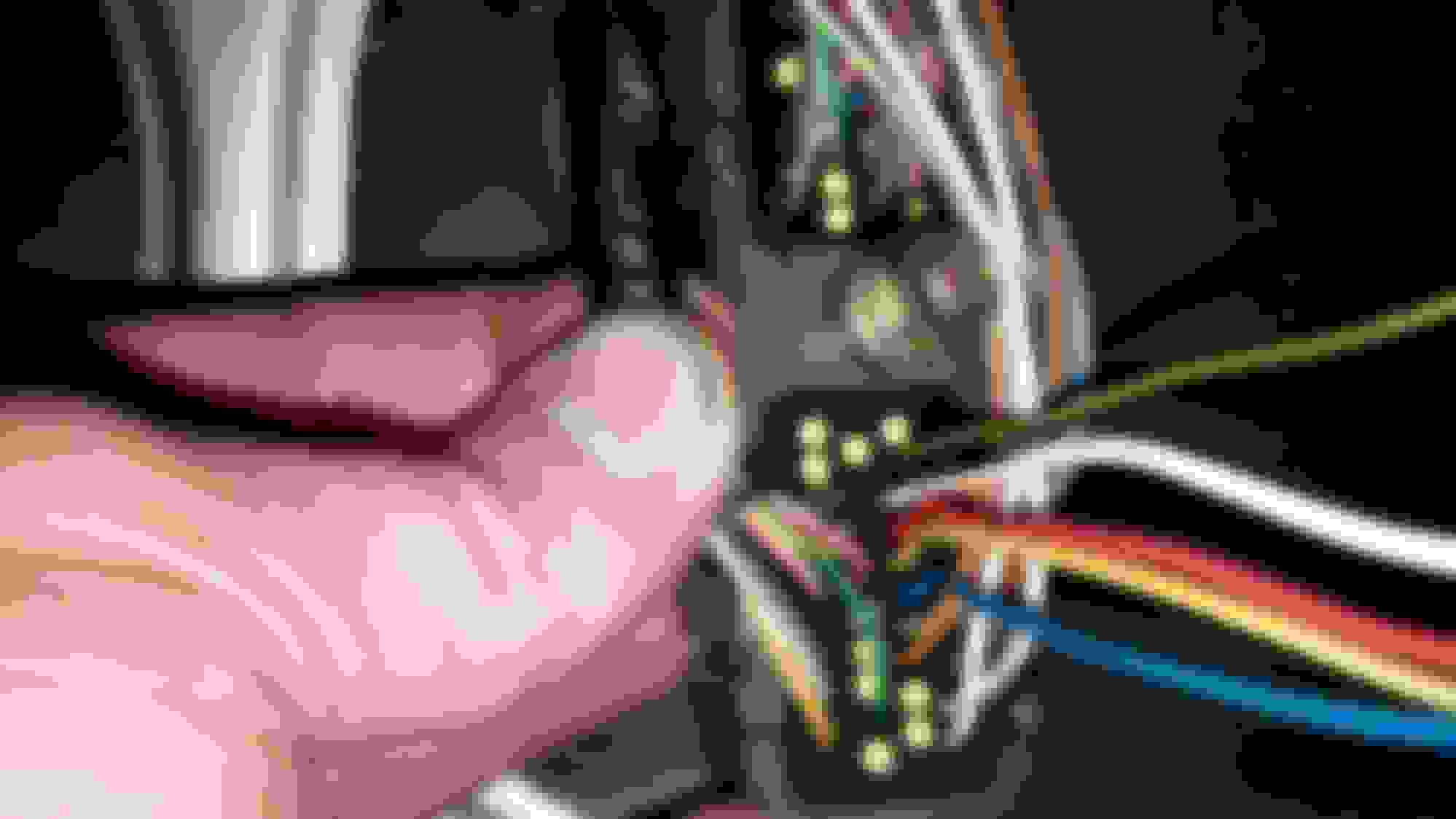
Nice and clear Picture of the 40 Pin ECU connector showing the top right BLUE/WHITE wire moved form pin B66 to B62
Pin B66 is just below the brown wire next to the three yellow caps, Originally the Blue/White wire was located here (below the brown wire)
Now it is Moved to Pin B62 to work with the ECU correctly
*EDIT* continuation of electrical from page 6
*** Ali SC3 or Moderator - Please edit this post into my other electrical post on page 4***
Finally finished all the wiring so the ECU will run properly with the stock Dizzy
Here you can clearly see the 5 new pins plugged into the ECU. The Red w/ Yellow wire is the IGF signal and the White and Green next to it it the IGT signal. The White and Green wire is the one you tap into to send the correct signal to the ECU. The 5 New Pins added next to the White and Green wire are as follows (1-Blue, 2-yellow, 3-Red, 4-White, 5-Black w/ Yellow) all of these a spliced into the White w/ Green
Here is a picture of the 5 wires soldered and heat shrunk.
close up of the 5 wires added, soldered, and heat shrunk
Remember this guy? This is the pipe I was going to use the Maxima IAT sensor with when just doing the ECU mod before boosting. Since I decided to do the turbo install all at once I needed the AEM AIT Sensor and a bung welded on so there wouldn't be any boost leaks on the IC piping. Turned out really well
First off, Sorry for the picture says ITA instead of IAT. I made this with Microsoft Paint at 2 a.m.
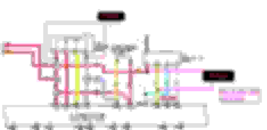
Here is an updated schematic showing what wires you will need to tap the IAT and MAP sensors into when doing the ECU mod on an OBDII car. Please keep in mind that the OBDII cars Mass Air Flow sensor uses a 12v reference for power and your new MAP and IAT use a 5v reference.
**YOU MUST TAP THE NEW MAP SENSORS AT THE TPS (throttle position sensor) IN ORDER TO MAKE IT WORK WITH THE ECU PROPERLY**
Your MAP Sensor Power wire will be the Blue w/ Red wire at the TPS.
Your MAP Sensor Signal wire will be the Blue w/ White wire originally located at the Mass Air Flow Sensor Connector. (you can De-pin it and pull it through the harness, or you can tap into in the harness near the injectors)
Your MAP Sensor Ground wire will be the Brown wire at the TPS
In order to function correctly with the ECU your IAT will only need a signal and a ground. It does not matter what wire goes where as it should read correctly.
Your IAT Signal wire will be the Yellow w/ Green wire originally located at the Mass Air Flow Sensor Connector
Your IAT Ground wire will be the Brown wire originally located at the Mass Air Flow Sensor Connector
Alright guys I got too tired to finish all these last night so I will start today with this before heading back out and trying to finish up some stuff on the intake runners..
I figured we could start the day with some Inspiration !!
Had this little guy laying in my back seat when I went to do the ECU stuff.. Put a nice smile on my face
R.I.P. Paul Walker
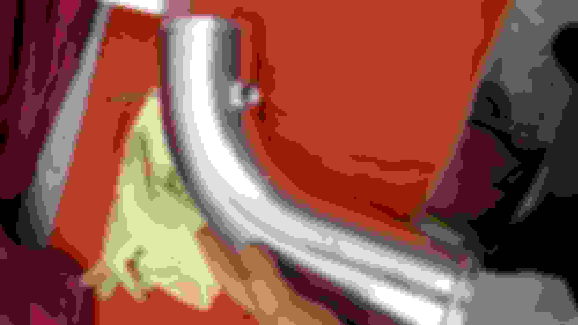
So this is the pipe pictured form earlier with the Maxima Grommet.
Since I am going forced induction now, I no longer need that Sensor and grommet because it will leak under boost.
So in turn I have drilled the hole slightly bigger to accept the weld on style bung for the AEM IAT Sensor
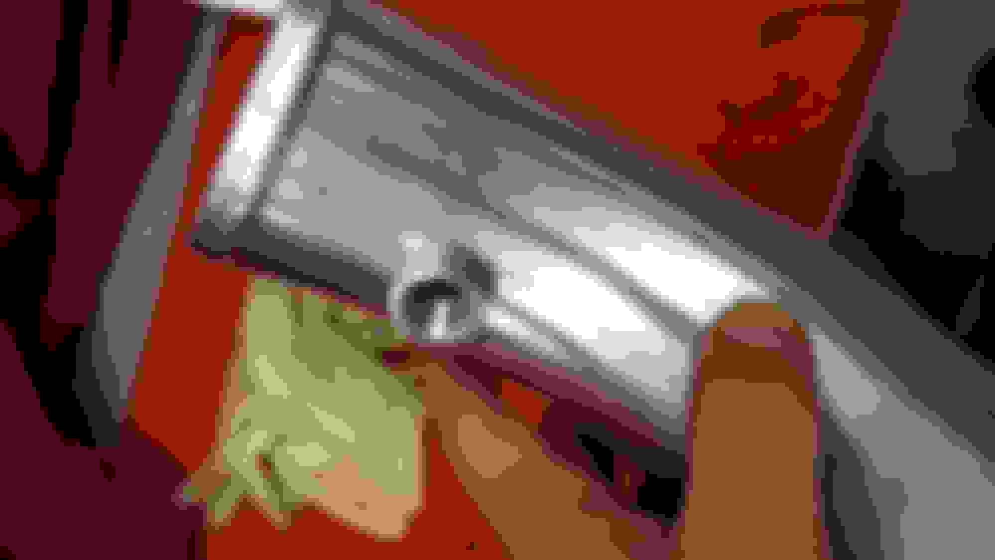
These bungs are Directional so be sure to weld them on the correct way. I have marked mine so it is silver on top and black on bottom
Here you can see the fitment is flush and the clearly seen Black ring I made with sharpie to indicate the bottom side
Another little peak at the fitment before welding
I hope to have this little guy welded up and the intake runners cleaned and prepped for paint by the end of the day.
Just as a quick question does anyone know what spark plugs would be better to run on an NA-T setup? I definitely don't want spark blowout under boost.. So I have heard NGK3330's or NGK6097's I believe both are pre-gapped at .031"
In the mean time guys, enjoy my little write up so far and can't wait to bring you more as there is still a lot to do.
Ok guys time for another update. So I went to NAPA to grab a set of those plugs, turns out NGK3330's and NGK6097's are both discontinued. So I just re-gaped my factory NGK's to .031" .. should work fine I hope.
Also started painting the runners and setting the block up to accept the cylinder head.. here is the progress so far
Got the block all cleaned up, no more carbon cleaned the cylinder walls and removed all the debris form cleaning. Also started to install the ARP Head studs
Clear top shot of the block before installing the cylinder head.
*Note when installing the ARP Head Studs while the engine is still in the car you must leave the rear two studs closets to the firewall out. This is because the head will not clear the firewall when installing. After the head is on you can install the last few studs.
Taking some key components off of the throttle body and y-pipe to prep for paint
Underside of throttle body and y-pipe picture for reference when re-assembling
Tapped off and primer painted first, then applied this high temp Dupli-Color Semi-Gloss Black
Close up
Throttle body taken apart, Tapped, and primer painted, then blasted with the same black
completed and looking very well might I add. I really like how these came out
Fully Assembled and ready for install.. I may have bumped the TPS when attempting to remove everything so I will probably need to reset that once on
Thanks Ross3857, it took me almost 3 years to save up and buy everything I needed, and I am still thinking of things as I am installing stuff lol. It is definitely an ongoing project so beware.
Originally Posted by Kris9884
Very good work and some very very handy wiring info. I'll be referencing this stuff soon enough, thank you very much!
I appreciate the compliment Kris9884, I figured if I was going to do a build thread I better make it count, especially since I have an OBDII car and I'm in slightly uncharted territory lol.


 04-14-15, 11:22 PM