When you click on links to various merchants on this site and make a purchase, this can result in this site earning a commission. Affiliate programs and affiliations include, but are not limited to, the eBay Partner Network.
Just reading your thread now, good progress and like the black interior. were you are the colorado 2014 toyota meet? I was there with my SC and my brother was there with the black supra.
For the IAT yeah they are all very similar. Since you are on the GTE ecu, don't bother even with sticking it in the intercooler piping the stock ecu is not that sensitive to the IAT, it just knows like cold, warming up and hot.
I have stuck mine before the turbo in the intake pipe where you do not have to worry about it sealing, and it works perfect there AFR's are spot on. back in the day on the stock ecu most just used a resistor or left the IAT hanging out in the engine bay, but if you get it in the intake pipe it would be good and that grommet would do the trick then. I would not put the grommet like that on the intercooler pipe, just asking for it to blow off eventually I would think I would defginately weld a bung on it for the intercooler pipe, or if its thick enough you may even get away with drilling and tapping it, and the GM sensors use a threaded fitting on the bottom. I found the GM IAT jams pretty well into one of the larger vacuum nipples on my intake pipe, so its been jammed in there for over a year now.
Ali thanks for chiming in, I did not make the meet this year as I was in Las Vegas when it happened. I did however go to 2012 and 2013 meets.
I already drilled the hole for the IAT in the IC Piping being an Idiot not thinking a head.. kinda interested how long it will last there under boost and not leak.. I've had good success with my SRT-4 like this @ 24psi so we will see.. I do eventually plan on ordering a weld on bung for it with a new sensor. I can see for sure if it was just chilling in the intake pipe it would work fine but since I'm staying stock Dizzy for now I cannot mock that up easily so I just placed it where it is.
Hopefully when I finally get to tear into this sucker you can swing by and we can throw some more theories around for the OBDII Auto trans. guys. We had a pretty good run in the TT-ECU mod thread that opened up a lot of answers.
IT should be ok and since you are on the map version the car will run and drive with boost leaks just fine although the boost might not be as punchy till you fix all leaks.
Yeah sure once you get working on it let me know I can come check it out, I don't live that far away but always fun to see another project and meet more people.
I looked up and found more differences in the signal. the GE one is also 12V and the gte PWM is 5v, so that even complicates it more and now I know why the relay did nothing. you would need the gte ecu > PWM filter (produces analog 5v waveform representing the duty cycle of the PWM signal) > then you would need to figure out the duty cycles it turns off and on at and set that in a microcontoller or comparator of some sort, and then use that output signal to trigger a 12V relay, and hope it all works. also you have to make sure the gte ecu sees the right resistance on the filter circuit.
When I arrived at that point I decided its not worth my time or brain power to make such a regular transmission work. my mod is budget minded so my answer is if you have to use the stock auto get a beefy trans cooler.. lol. then when it eventually dies in a high power up/downshift you can just manual swap it or spend some time installing and wiring up a gte auto trans. wiring up the gte trans Is probably just a handfull of wires anyways but I think I have contributed enough to the tt ecu mod and I have decided I am not going to be making that inbetween circuit, just don't have that kind of spare time anymore, hope you guys understand but what I wrote above someone could use to make one.
To be honest I am actually really glad I could contribute and we uncovered everything we did. now people know how much of a complete PITA it is to get one little part of the trans working (TCC Lock-up). You are very right; just run a bad *** Trans. Cooler and deal with ****ty gas mileage or go TT-Auto if you are trying to stay Auto..
I plan on ordering the built TT-Auto Trans from ATFSpeed eventually and not worrying about it from there. I will just need a helping hand figuring out the wires I need to pin into the Aristo ECU and what connectors to run them to on the USDM TT-Auto.. then wa-la built TT Trans and a Confirmed working operation of a USDM TT-Auto with an Aristo ECU on and OBDII Car!!!.. what a nice break through that would be (even though it will not actually be an OBDII anymore lol)
well the nice part is the gte trans on obd1 and obd2 is literally the same trans. basically the supra GTE got the more advanced auto trans early, well because it sort of needs it. the wiring is also the same for JDM and USDM I think so literally you can borrow the wires from any non-vvti 2jzgte auto harness, but I figure the JDM ones may need a little extending. that is where I would start and I can show you how to put them in yours or you can figure out how many connectors are missing or different and try and go that route but it wont be nearly as fun or easy.
well the nice part is the gte trans on obd1 and obd2 is literally the same trans. basically the supra GTE got the more advanced auto trans early, well because it sort of needs it. the wiring is also the same for JDM and USDM I think so literally you can borrow the wires from any non-vvti 2jzgte auto harness, but I figure the JDM ones may need a little extending. that is where I would start and I can show you how to put them in yours or you can figure out how many connectors are missing or different and try and go that route but it wont be nearly as fun or easy.
I planned on grabbing a OBDI TT-Auto and Harness and just adding the wires to the SC's harness since I am running the Aristo ECU Mod. Everything should be fairly straight forward. I just need to cross reference pin locations at the ECU and make sure they are going to the correct connectors at the new trans.
once this is finished we will have a for sure fix for Auto guys looking to boost. Now its just a race to see who finishes it first Me or BuffNStuff lol
Small update.. so the injectors fell through thanks to USPS loosing them in the mail
It's a shame because Tabaka gave me such a killer deal on them..
However there is rims in the mix now.. Looking at a staggered set of 19's off of a 2011 G37s Coupe .. not sure on the specs just yet but will post once they are purchased and have pics to post.. they will be a 225/45/19 front and a 245/40/19 rear .. should sit nice and I like the spoke design.. and +1 for clearing BBK's..
So its been sometime since I posted here. Things got crazy and me and my boyfriend bought a Condo so that has put a major hold on the car. Here is a little a update tho ... Rims are official!!!
They are 19x8.5 front +45 and 19x9 rear +43 .. I am going to run 5mm spacers to put them where i want them and boom.. summer tires engage.
Here are the pics of them. they will be getting sent off to resurfacing and powder coating fairly soon hopefully.
ANY COLOR IDEAS??? Keep in mind... SPOILER >> SPOILER>> the Car will be getting wrapped Purple Chrome on Christmas!! excited for that too.
So once again, it is finally summer and I am ready to undergo some transformations FINALLY!!
I have been plotting and planning quite a bit since my last post and here is where the SC stands today (3-22-15)
Rims are officially going to be finished getting refinished this week and I should have them by Thursday.
I will be making a trip to Colorado Springs the weekend of April 4th-5th and storing my winter wheels and tires and putting on the Infiniti Rims. the set up is 19x8.5 +45 Front and 19x9 +43 Rear, I will be running 5mm Wheel Spacers making the off-set +40 Front and +38 Rear will post pics of this set up once installed.
Did some brain-storming and decided to pull the head off and do some stuff before boosting.
SSSSOOOOO
On April 11th the tare-down starts. I will be replacing the head gasket with a Factory Toyota TT-Head Gasket, Installing ARP Head Studs, due to high mileage (200K) I am also installing Crower Springs and Titanium Retainers, lapping the stock valves and cleaning all carbon from the cylinder head, Replacing the valve oil seals with factory Toyota ones, Gates Racing Timing Belt, Water Pump, Tensioner and Idler, and Cam and Crank seals
Once all is completed in April I plan on driving it like this for the remainder of the month and in mid May I will officially put him down to go forced induction.
Alright guys, and girls.. Enough with the talking and more with the building.. back on track and as promised, here are the pics of the 19" rims installed. Feedback is appreciated lol. Also in the mix I have included the teaser pic of what is happening right now !!
As of 6:30 today (4-10-15) the SC has been put under the knife, I will be posting a series of pics over the next few weeks of progress of the T-belt, water pump, cam seals, crank seal, distributor o-rings, TT - Head Gasket, ARP Studs, Crower Springs and Ti Reatiner install along with new valve stem oil seals, and any other goodies I may snap while I"m in the process of this
LETS BEGIN !!!!!!!
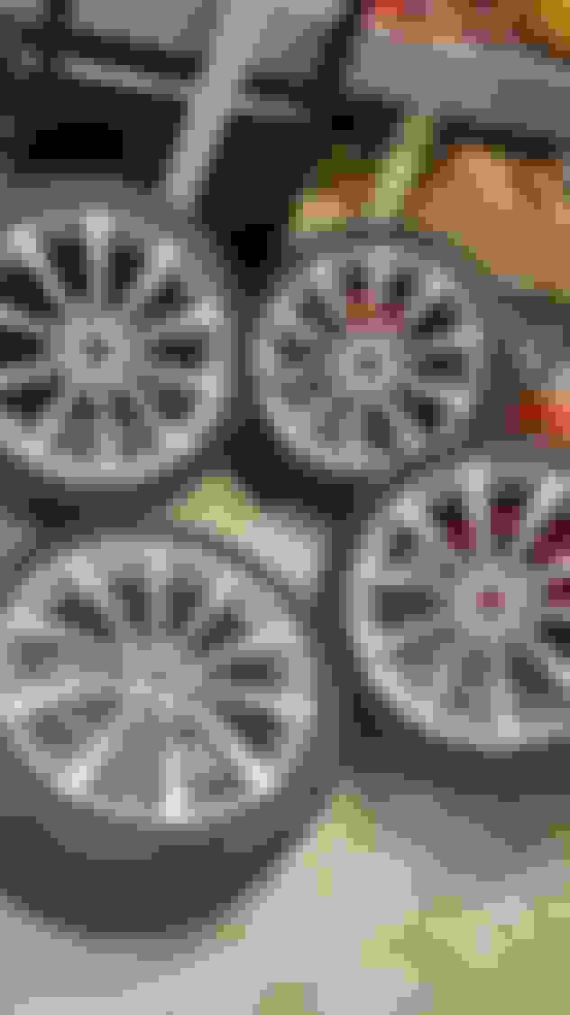
Just a few posts back these rims were all rashed up. Well here they are fully refinished and repainted one shade lighter ready for install
Hours before the swap decided to take one last picture of those beautiful stock 16" Chromes
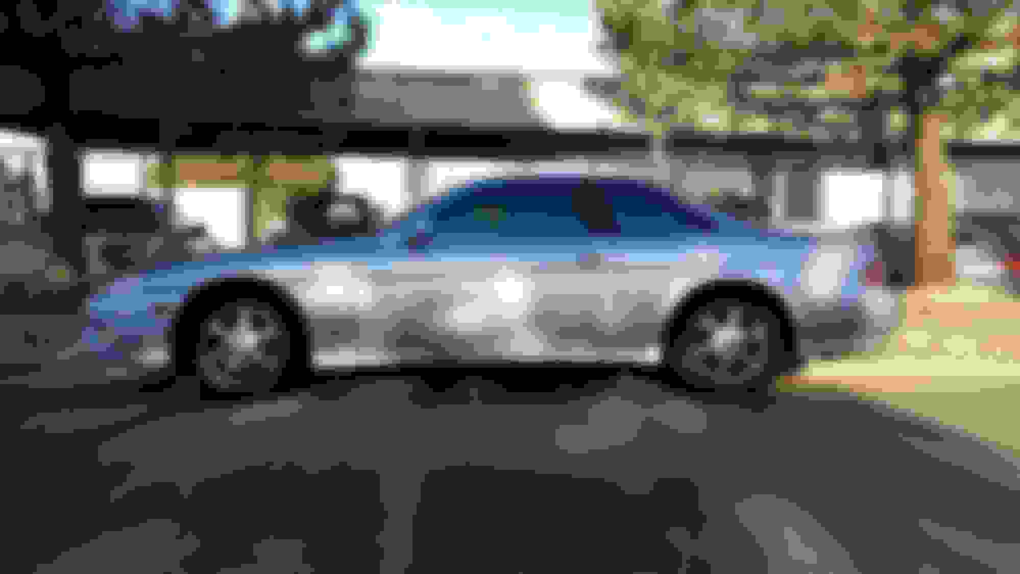
WAH-LAH !!! installed and quite nicely might I add
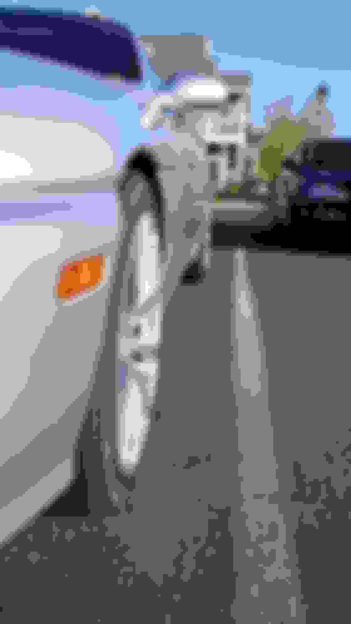
Stance from the front with 5mm Spacers
Stance from the rear with 5mm Spacers
What an exciting box to get in the mail !!
Now that is pretty.. About to replace those old, tired, abused, 190,710 mile Springs with some new Crower's.. Lets close those valves
AND .. the finishing touch Titanium Retainers to top off the magic of the project
I can't hardly wait to bring you guys more goodies and get some input as for now its dinner time and hope to see you all again soon.. more work tomorrow!!
I want to see more pics!!! This is basically the same route taking in the nat setup! Same intercooler! if you could please .do Have any more pics of the piping. Routing. Fitment? It's looks awesome! Same color as mine as well lol
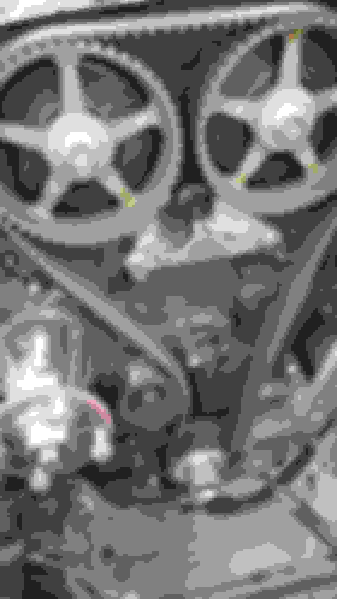
Ready to remove the Timing Belt and separate the harness
Separating the Harness and moving it to one side (Drivers) to access the lower runner bolts and remove the lower runner
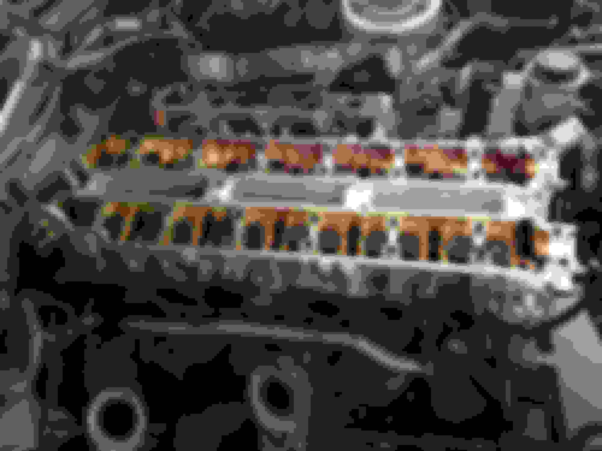
Timing belt off, rear timing cover removed,Cam Gears Removed,and starting to remove cam caps. Ready for Exhaust Manifold Removal and Water Pump removal
Setting up the caps in order and side sequence for re-installation
One down, One to go! Plus this made for a really good Instagram pic for all my followers lol
DAY 2 -- Water Pump Removed, Exhaust Manifold Removed, Water outlet hose on back of cylinder head removed. slight inspection for abnormalities/cracks, prepping for Cylinder head removal, just need that Special Torx to finish..
Well all, that sums up the Weekend... Monday night I will have the Torx to remove the Cylinder Head and post more pics for everyone
I want to see more pics!!! This is basically the same route taking in the nat setup! Same intercooler! if you could please .do Have any more pics of the piping. Routing. Fitment? It's looks awesome! Same color as mine as well lol
Golden95SC I will gladly post detailed pics and process of inter-cooler piping when I get there.. I am still in the process of cleaning and slightly rebuilding the cylinder head at this time. Shortly I hope to be adding pics and what not of everything.. I love sharing the challenges of a good NA-T Set up..
Honestly I am most excited about the gauges and mounting can't wait to show that.
I have more pics to post from today, finally got the cylinder head off and taking it to work tomorrow. hopefully I can catch a long enough break to get them all up lol
 07-25-14, 08:22 AM


 Now its just a race to see who finishes it first Me or BuffNStuff lol


 can't wait to show that.